

Page 1

FPC 71X0 fan less panel PC
12”/15”/17” touch screen
Atom all-in-one fan less system
User manual
Page 2

FCC Statement
This device complies with part 15 FCC rules. Operation is subject to
the following two conditions
This device may not cause harmful interference.
This device must accept any interference received including
interference that may cause undesired operation.
This equipment has been tested and found to comply with the limits for a class "a"
digital device, pursuant to part 15 of the FCC rules. These limits are designed to
provide reasonable protection against harmful interference when the equipment is
operated in a commercial environment. This equipment generates, uses, and can
radiate radio frequency energy and, if not installed and used in accordance with the
instruction manual, may cause harmful interference to radio communications.
Operation of this equipment in a residential area is likely to cause harmful interference
in which case the user will be required to correct the interference at him own expense.
:
I
Page 3

Copyright Notice
This document is copyrighted, 2009. The information provided in this document has
been carefully checked for accuracy at the time of publication. No representations or
warranties, either expressed or implied, with respect to the contents hereof and
specifically disclaims any warranties, merchantability or fitness for any particular
purpose.
Any software described in this manual is sold or licensed “as is”. Should the programs
prove defective following their purchase, the buyer assumes the entire cost of all
necessary servicing, repair, and any incidental or consequential damages resulting
from any defect in software.
The manufacture reserves the right to revise this publication and to make changes
from time to time in the contents hereof without obligation to notify any person of such
revision or changes.
No part of this publication may be reproduced, stored in a retrieval system, or
transmitted in any form of or via any means without the prior written permission of the
manufacture.
Trademark Acknowledgement
All brand, company and product names used for identification in this document are
trademarks or registered trademarks of their respective companies.
© Copyright 2009, Version 1.0
All rights reserved.
II
Page 4

Unpacking the FPC 71X0 Series
After unpacking the FPC 71X0 carton, check to make sure all the following
items are included and in good condition.
FPC 71X0 main system x 1
Accessories:
AC Power Cord x 1
Power Adapter x 1
User guide CD & driver x 1
Make sure that all of the items listed above are present. If any of the above items is
missing, contact your supplier immediately.
Warranty
All products are warranted against defective materials for one year starting from the
date of delivery to the original buyer.
III
Page 5

Important Safety Precautions
1. Before getting started, read these instructions and save them for later reference.
2. Please disconnect this equipment from any AC outlet before cleaning. Clean
a
damp or dry cloth only. Do not spray any liquid cleaner directly.
3. The power outlet socket used to plug in the computer power cord must be
located near the system and easily accessible. Do not use outlets on the same
circuit of the systems that are regularly switched on and off.
4. Do not expose the power cord, extension cord and power outlet to moisture or
traffic intensive walkways.
5. Install the equipment on a sturdy and reliable surface to prevent damage caused
by dropping.
6. If the Equipment is sharing an extension cord with other devices, make sure the
total ampere rating of the devices plugged into the extension cord does not
exceed the cord’s ampere rating.
with
7. If an operating system is not installed, an operating system must be loaded first
before installing any software into the equipment.
8. Disconnect the power cord from the computer before any installation of internal
components. Make sure both the computer and the external devices are turned
off. A sudden surge of power may damage sensitive
components.
Also make
sure the computer is properly grounded.
9. During installation of any internal components, be sure to ground yourself to
discharge any static electricity. Most electronic components are highly sensitive
to static electric charge. Use a grounding wrist strap and place all electronic
components in any static-shielded devices. If a wrist-grounding strap is not
available, ground your self by briefly touching an unpainted piece of metal.
10. If the equipment is equipped with a touch panel, avoid using sharp or metallic
objects to operate the touch panel. Scratches on the touch panel may cause
mal-calibration or serious damage to the panel.
11. The brightness of the flat panel display will decrease with use over long periods
of time. However, hours of use will vary depending on the application
environment.
12. FPC 71X0 is equipped with a touch panel, avoid using sharp or metallic objects to
operate the touch panel. Scratches on the touch panel may cause mal-calibration
or serious damage to the panel.
13. The LCD panel display is not resistive to shock or vibration. When disassembling
FPC 71X0, make sure the LCD panel is properly and securely installed.
IV
Page 6

C
HAPTER
1
Contents
I
NTRODUCTION
...................................................... 1-1
1.1 General Information .................................................................1-1
1.2 Specifications ..........................................................................1-2
C
HAPTER
2.1 Identifying the System .............................................................2-5
2.2 First Time System Setup .........................................................2-6
2 U
2.1.1 Front view ............................................................................................ 2-5
2.1.2 Rear view ............................................................................................. 2-5
2.2.1 Hardware Installation Procedure ......................................................... 2-6
2.2.2 System BIOS Setup ............................................................................. 2-6
2.2.3 Operating System and Driver .............................................................. 2-7
SING THE SYSTEM
............................................... 2-5
2.3 Installation Memory Module.....................................................2-8
C
HAPTER
C
HAPTER
3 I
4 S
NPUT/OUTPUT CONNECTORS
YSTEM MAIN BOARD
.........................................
................................. 3-9
4.1 Main Board Dimensions ........................................................ 4-11
4.2 Main Board Layout ................................................................4-12
4.3 Main Board Jumpers and Jumper Setting .............................4-13
4.3.1 JP1: LVDS Panel Power Select ......................................................... 4-13
4.3.2 JP2, JP3, JP6 COM2 Select RS232/422/485.................................... 4-13
4.3.3 JP4: COM5, COM6 RS232 +5V/+12V Power Setting ....................... 4-14
4.3.4 JP7: COM3, COM4 RS232 +5V/+12V Power Setting ....................... 4-14
4.3.5 JP8: COM1, COM2 RS232 +5V/+12V Power Setting ....................... 4-14
4.3.6 JBT: Clear CMOS Contents ............................................................... 4-15
4.4 Connectors and Pin Assignment............................................4-16
4.4.1 CN1: Inverter BKL Connector ............................................................ 4-17
4.4.2 CN2: 4 Pin Power Output Connector................................................. 4-17
4.4.3 CN3: USB Connectors ....................................................................... 4-17
4.4.4 CN4: USB Connectors ....................................................................... 4-17
4.4.5 J1: PW/Reset Switch and Indicator Connector.................................. 4-18
4.4.6 J2: MSR Connector............................................................................ 4-18
4.4.7 J3: COM3/COM4 D-SUB 9 Pin Connector ........................................ 4-18
4.4.8 J4: COM2+ CRT (D-SUB 9Pin+D-SUB 15Pin Connector) ................ 4-19
4.4.9 JP5: Digital 4-In 4-Out I/O Connector ................................................ 4-19
4.4.10 LAN1, LAN2: RJ45 + USB0/1, USB2/3 Connectors .......................... 4-20
4.4.11 SATA1, SATA2: SATA HDD Connector .............................................. 4-20
4.4.12 FAN1, FAN2: CPU Fan Power Connector ......................................... 4-20
4-11
Page 7

4.4.13 I_SP: Internal Speaker Connector ..................................................... 4-20
4.4.14 PW_IN: DC Power In (DC12V) .......................................................... 4-20
4.4.15 COM1: COM Port Connector ............................................................. 4-21
4.4.16 COM5: COM Port Connector ............................................................. 4-21
4.4.17 COM6: COM Port Connector ............................................................. 4-21
4.4.18 AU1: Line Out, Mic Connector ........................................................... 4-21
4.4.19 FDD1: Floppy Drive Connector.......................................................... 4-22
4.4.20 LPT1: Parallel Port (26Pin Header) ................................................... 4-22
4.4.21 LCD1: LVDS Panel Output................................................................. 4-23
4.4.22 MODEM1: Onboard Modem Connector ............................................ 4-23
4.4.23 IDE1: IDE Connector ......................................................................... 4-24
4.4.24 PS1: PS2 Keyboard &Mouse connector............................................ 4-24
C
HAPTER
5 A
WARD
BIOS
S
ETUP
...........................................
5.1 Starting Setup ........................................................................5-25
5.2 Award BIOS Setup ................................................................5-26
5.3 Standard CMOS Features .....................................................5-27
5.4 Advanced BIOS Features ......................................................5-29
5.5 Advanced Chipset Features ..................................................5-32
5.6 Integrated Peripherals ...........................................................5-34
5.7 Power Management Setup ....................................................5-38
5.8 PnP/PCI Configuration ..........................................................5-40
5.9 Frequency/Voltage Control ....................................................5-41
5.10 Load Fail-Safe Defaults .........................................................5-42
5.11 Load Optimized Defaults .......................................................5-43
5.12 Set Supervisor/User Password..............................................5-44
5.13 Save & Exit Setup..................................................................5-45
5.14 Exit Without Saving ...............................................................5-46
5-25
C
HAPTER
6.1 Chipset Driver Installation......................................................6-47
6.2 Ethernet Driver Installation ....................................................6-53
6.3 VGA Driver Installation ..........................................................6-58
6 D
RIVERS INSTALLATION
....................................... 6-47
6.1.1 Windows XP....................................................................................... 6-47
6.1.2 Windows VISTA ................................................................................. 6-48
6.1.3 Windows POSReady 2009 ................................................................ 6-50
6.2.1 Windows XP....................................................................................... 6-53
6.2.2 Windows VISTA ................................................................................. 6-54
6.2.3 Windows POSReady 2009 ................................................................ 6-56
6.3.1 Windows XP....................................................................................... 6-58
Page 8

6.3.2 Windows VISTA ................................................................................. 6-59
6.3.3 Windows POSReady 2009 ................................................................ 6-61
6.4 Audio Driver Installation.........................................................6-63
6.4.1 Windows XP....................................................................................... 6-63
6.4.2 Windows VISTA ................................................................................. 6-64
6.4.3 Windows POSReady 2009 ................................................................ 6-66
6.5 Wireless LAN Driver Installation ............................................6-69
6.6 Touch Driver Installation ........................................................6-70
Page 9

FPC 71X0
U
ser M
anual
1-1
Chapter 1 I
This chapter includes the FPC 71X0 series system background information.
General Information
Specification
Dimensions
NTRODUCTION
1.1 General Information
FPC 71X0 series is a fan less mini size panel PC with a compact aluminum chassis
as a huge heat sink, which delivers reliable, easy-maintenance, LCD panel and quiet
industrial grade mini size computer. Featuring Atom processor, FPC 71X0 series
combines enhanced digital media performance with unique thermal solution, and
minimizes power consumption to as little as 5 watts when running at the speed of 1
GHz, bringing up a quieter and cooler system. The versatile FPC 71X0 series can
support one 2.5" HDD drive bay (SSD/DOM is available for option) and DDR2 memory
up to
2GB. The myriad of I/O ports located at front side including one 10/100 /1000 Ethernet
LAN ports, four USB 2.0 ports, four serial ports for FPC 7120/150/170 (3x RS232; 1x
RS232/422/485), PS/2, VGA, Audio port and one built-in CF socket for flexible
expansion capability.
Page 10

FPC 71X0
U
ser M
anual
1-2
1.2 Specifications
SYSTEM
CPU
•
Onboard Intel Atom N270 processors (1.6GHz/FSB 533MHz)
•
Main Chipsets: Intel i82945GSE+ICH7M
System Memory
•
2 x 240 pin DIMM up to 2GB DDR2
Graphics
•
945GSE integrated GMA950, share system memory (up to 224MB)
•
Support dual display mirroring/multiple mode
Networking
•
Realtek RTL8111B 10/100/1000 Base-T fast Ethernet
•
802.11g Wireless LAN (Optional)
Audio
•
VIA HD Codec VT1708 (Lin-out, Mic)
Power Supply
y
DC 12V power input
OS
y
Windows
XP/XPE/VISATA/POSReady
2009
LED
•
Power, HDD
DISPLAY
Touch Screen
y 5-wire Analog resistive (HIGGSTEC, ELO)
LCD
y FPC 7120/150/170: 12” TFT/15” TFT/17” TFT
Page 11

FPC 71X0
U
ser M
anual
1-3
Resolution
y FPC 7120: 800 x 600
y FPC 7150: 1024 x 768
y FPC 7170: 1280 x 1024
Brightness
y FPC 7120: 350 cdm
y FPC 715: 250 cdm/
y FPC 7170: 300 cd/m
Storage Device
HDD
•
1 x 2.5" SATA HDD
Compact Flash
•
4G or 8G CF card (Optional)
I/O PORTS
USB
2
2
2
•
6 x USB 2.0 ports (4 x rear connectors; 2 x pin header inside)
Serial Ports
•
FPC 71X0 120/150/170:
- 4 x DB-9 (COM1 / 2 / 3 / 4)
- RS232: COM1 / 3 / 4
- RS232/422/485: COM2
- Support pin9 +5V/12V selection by jumper
LAN
•
2 x RJ-45 interface (Gigabit LAN 10/100/1000)
Page 12

FPC 71X0
U
ser M
anual
1-4
PS/2
•
2 x PS/2 ports (for keyboard and mouse)
Audio
•
1x line-out and 1x Mic in
VGA
•
1 x DB15 VGA interface for dual display
MECHANICAL & ENVIRONMENTAL
Dimension
•
FPC 7120: 260 x 351 x 86.5 (H x W x D mm)
•
FPC 7150: 306 x 412 x 88 (H x W x D mm)
•
FPC 7170: 350 x 445 x 90.4 (H x W x D mm)
Weight
•
FPC 7120: 4.5 KG
•
FPC 7150: 5.5 KG
•
FPC 7170: 7.25 KG
Temperature
y
Operating: 0~40°C
y
Storage: -20~60°C
Humidity
y 10%~90%
EMC & Safety
y CE, FCC
Specifications are subject to revision or update without notice.
Page 13
3-5
Chapter 2 U
SING THE SYSTEM
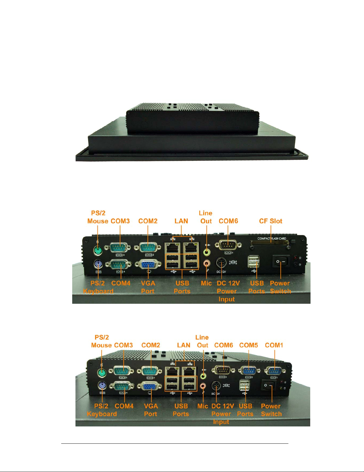
2.1 Identifying the System
2.1.1 Front view
2.1.2 Rear view
•
FPC 7120/7150/7170
•
FPC 7150A/7170A (6-Serial ports version)
FPC 71X0 User Manual
Page 14

3-6
2.2 First Time System Setup
To set up the FPC 71X0 series for the first-time, you should have the following
items ready. These items are either included in the accessory box or available from
your local computer parts store.
•
FPC 71X0 Utility CD (Included)
•
Power cord (Included)
•
PS/2, AT or USB Keyboard (Not included)
•
PS/2 or USB Mouse (Not included)
•
USB CD-ROM Drive (Not included)
•
Operating System (OS) Installation CD (Not included)
2.2.1 Hardware Installation Procedure
(Prior to turning the power on)
1. Connect a PS/2 keyboard or AT keyboard to the PS/2 keyboard port, or an
USB keyboard to a USB port. If you are using an AT keyboard, you need an
adapter (AT to PS/2 KB) for this connection.
2. Connect the PS/2 mouse to the PS/2 mouse port, or an USB mouse to an
USB port.
3. Connect the male end of the power cord to an electrical outlet.
4. Connect the female end of the power adapter cord to the AC inlet located at
the rear side of the FPC 71X0.
2.2.2 System BIOS Setup
If you are a commercial user, the FPC 71X0 series should have been set up and
configured by your distributor already. In the case where you may find it necessary to
change some system configuration information, you will need to run the Basic Input
Output System (BIOS) setup program. Under the following conditions, the CMOS
settings may be changed:
1. The system is starting and being configured for the first time with new
components.
2. The hardware devices attached to the FPC 71X0 system have been changed.
3. The CMOS memory has lost power and the configuration information has been
erased.
The BIOS setup program is stored in ROM, which can be accessed by pressing
<DEL> key on the keyboard immediately when the system is powered on. In order to
retain the specified setup information when the system power is turned off,
system
setup information is stored in a battery-backed CMOS RAM. The battery is to
the
FPC 71X0 User Manual
Page 15

3-7
ensure the settings will not be erased when the computer is turned off or reset. When
the computer is powered on again, the system will read the settings stored in the
CMOS RAM and compare them to the equipment check conducted during the power
on self-test (POST). If any error or mismatch occurs, an error message will be shown
on the screen and the computer will be prompted to run the setup program.
2.2.3 Operating System and Driver
The standard FPC 71X0 series system may not be equipped with an operating
system (OS). If you are a commercial user, the system is likely to have been pre-
installed with a proper operating system and software drivers by your dealer or
system integrator. If the system is not pre-installed with any system OS and drivers
or you intend to install your preferred ones, you will need to load an OS and
software into the system.
1. Use the external IDE Cable (optional) to connect a USB CD-ROM Drive to
an
OS from a bootable CD. Recent releases of operating systems include setup
load
programs that load automatically and guide you through the installation. You can
also refer to your OS user manual for instructions on formatting or partitioning the
hard disk drive before any software installation.
2. Install software drivers for your operating system and any peripherals that are
connected. The FPC 71X0 series utility CD includes software drivers for
Chipset driver, Audio, LAN, Touch, Wireless and VGA Display drivers. See
driver installation chapters for more information.
FPC 71X0 User Manual
Page 16
3-8
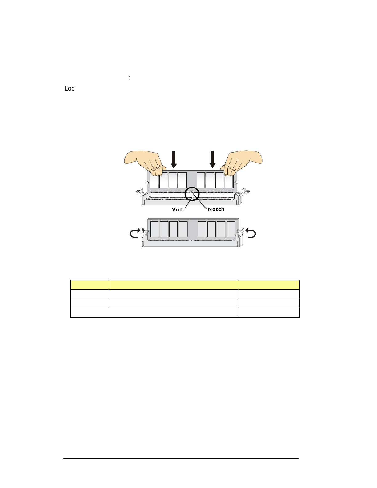
2.3 Installation Memory Module
The FPC 71X0 series with BI-946ID main board provides two 240-pin DIMM slot. The
socket supports up to 2GB DDR2 533MHz. When installing the Memory device, please
follow the steps below
Locate the DIMM slot in the motherboard.
1. Unlock a DIMM slot by pressing the retaining clips outward.
:
2. Align a DIMM on the socket such that the notch on the DIMM matches the break
on the slot.
3. Firmly insert the DIMM into the slot until the retaining clips snap back in place and
the DIMM is properly seated.
Available DDR2 configurations refer to the table below for available DDR2
configurations on the main board.
Slot
DIMM1
DIMM2
Maximum supported system memory
Module
512MB,
512MB,
Size
1GB
1GB
Tota
l
512MB-1GB
512MB-1GB
512MB-2GB
FPC 71X0 User Manual
Page 17
3-9
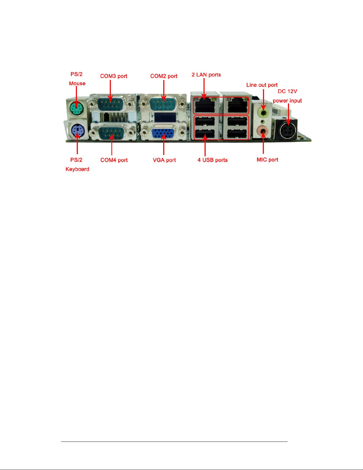
Chapter 3 I
PS/2 Keyboard and PS/2 Mouse
NPUT
/O
UTPUT CONNECTORS
The FPC 71X0 series provides two connector supports PS/2 interface. In other
cases, especially in embedded applications, a mouse is not used. Therefore, the
BIOS standard setup menu allows you to select* “All, But Keyboard” under the “Halt
On”. This allows no-keyboard operation in embedded system applications without
the system halting under POST.
Audio Interface
The VIA VT1708A chipset provided capabilities of VIA HD and supporting the high
definition HD Audio standard for a whole new immersive surround sound
experience. The VIA Vinyl VT1708A deliver top quality audio performance,
supporting the latest 8-channel, 24-bit, 192KHz audio content for an all-round high
fidelity experience. The audio interface includes two jacks, microphone-in and
line-out.
Serial COM Ports
Six RS-232 ports with 16550 UART (or compatible) with 16-byte FIFO buffer. One
optional COM port (COM2) supports RS232/422/485 choice through jumper
setting.
FPC 71X0 User Manual
Page 18

3-10
Network Interface
The Realtek RTL8111B Gigabit Ethernet supports the PCI Express 1.0a bus
interface for host communications with power management and is compliant with
the IEEE 802.3u specification for 10/100Mbps Ethernet and the IEEE 802.3ab
specification for 1000Mbps Ethernet. The Ethernet port provides a standard RJ-45
jack.
USB Ports
Four USB (two is optional) devices may be connected to the system through an
adapter cable. Various adapters may come with USB ports. USB usually connect
the external system to the system. The USB ports support hot plug-in connection.
Anyway, you should install the device driver before you use the device.
External VGA
FPC 71X0 series has one VGA port that can be connected to an external
CRT/LCD monitor. Use VGA cable to connect to an external CRT/LCD monitor,
and connect the power cable to the outlet The VGA connector is a standard 15-pin
D-SUB connector.
FPC 71X0 User Manual
Page 19
FPC 71X0
User
Manual
4-11
Chapter 4 S
YSTEM MAIN BOARD
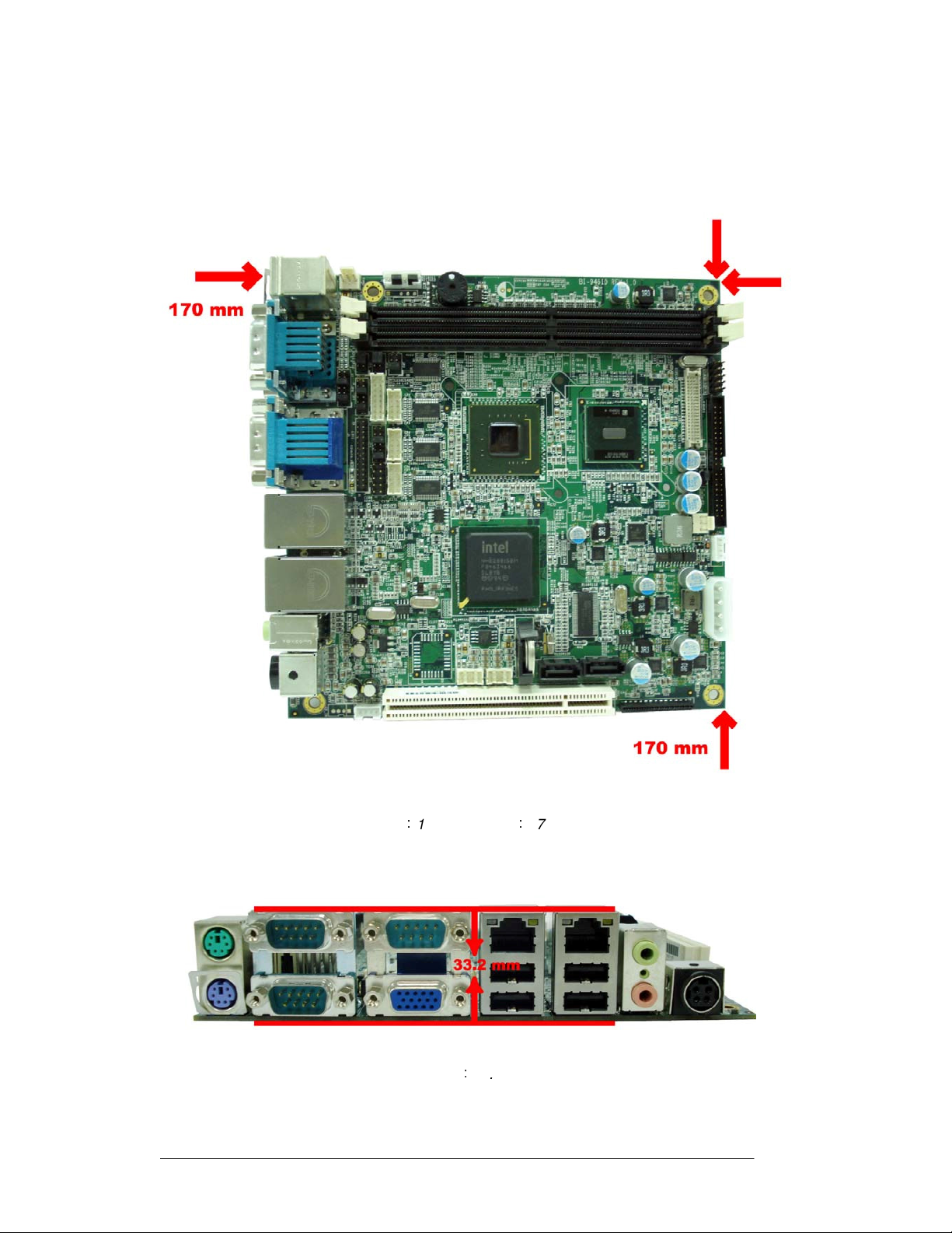
4.1 Main Board Dimensions
Width:170mm Length:170mm
Height:33.2mm
Page 20
FPC 71X0
User
Manual
4-12
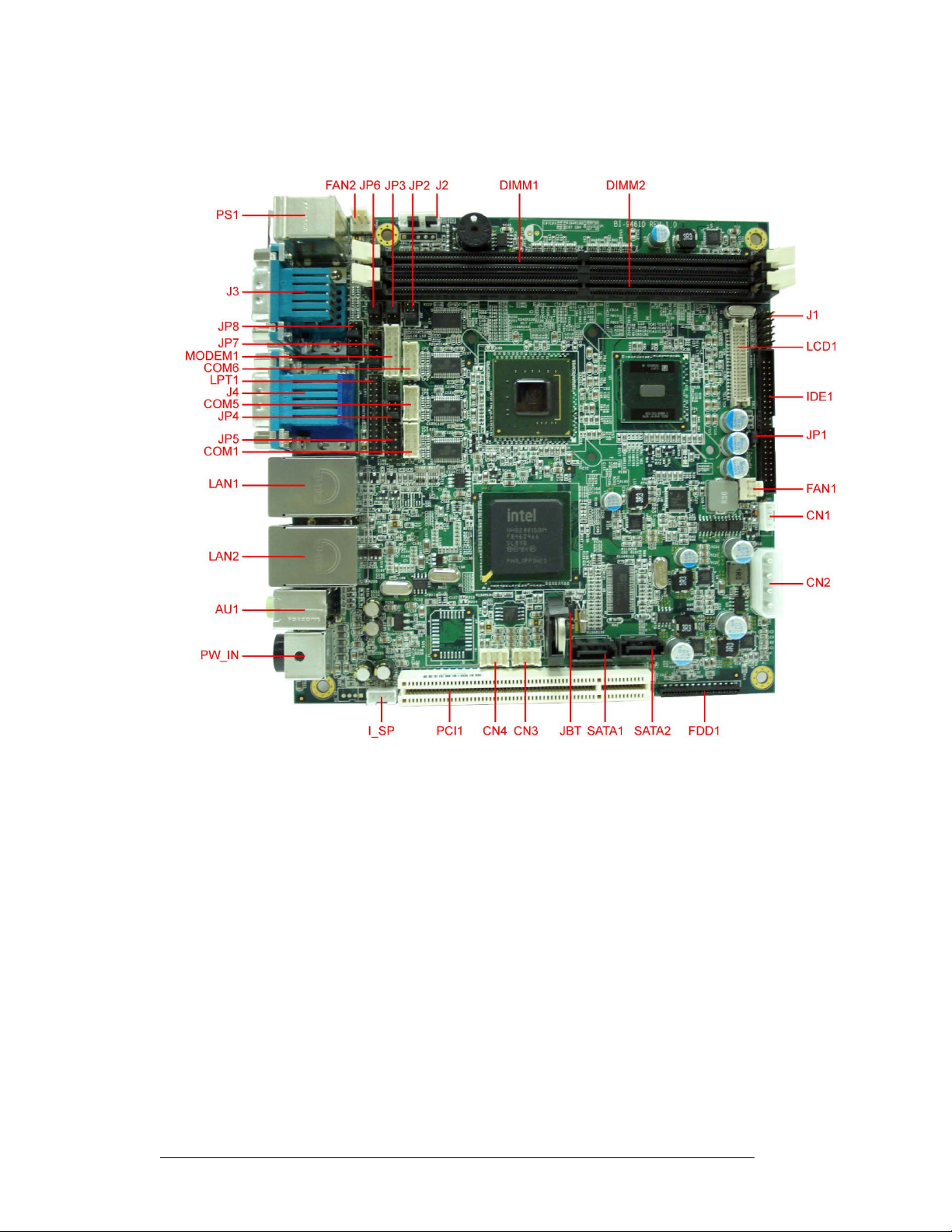
4.2 Mai
n Boa
r
d Layout
Locating Jumpers and Connectors (front side)
Page 21
FPC 71X0
User
Manual
4-13
4.3 Mai
n Boa
r
d Jumpers and Jumper Setting
Label
Function
Note
JP1 LVDS Panel Power Selector
JP2 Clear CMOS Contents
JP3 CPU Frequency Select
3x1 header, pitch 2.0 mm
3x1 header, pitch 2.0 mm
3x1 header, pitch 2.0 mm
JP4 COM5, COM6 RS232 +5V/+12V Power Setting 2x6 header, pitch 2.0 mm
JP6 RS232/422/485 Selector
2x3 header, pitch 2.0 mm
JP7 COM3, COM4 RS232 +5V/+12V Power Setting 2x6 header, pitch 2.0 mm
JP8 COM1, COM2 RS232 +5V/+12V Power Setting 2x6 header, pitch 2.0 mm
JBT Clear CMOS Contents
4.3.1 JP1: LVDS Panel Power Select
JP1
3x1 header, pitch 2.0 mm
LVDS Panel Power
3.3V (default)
5V
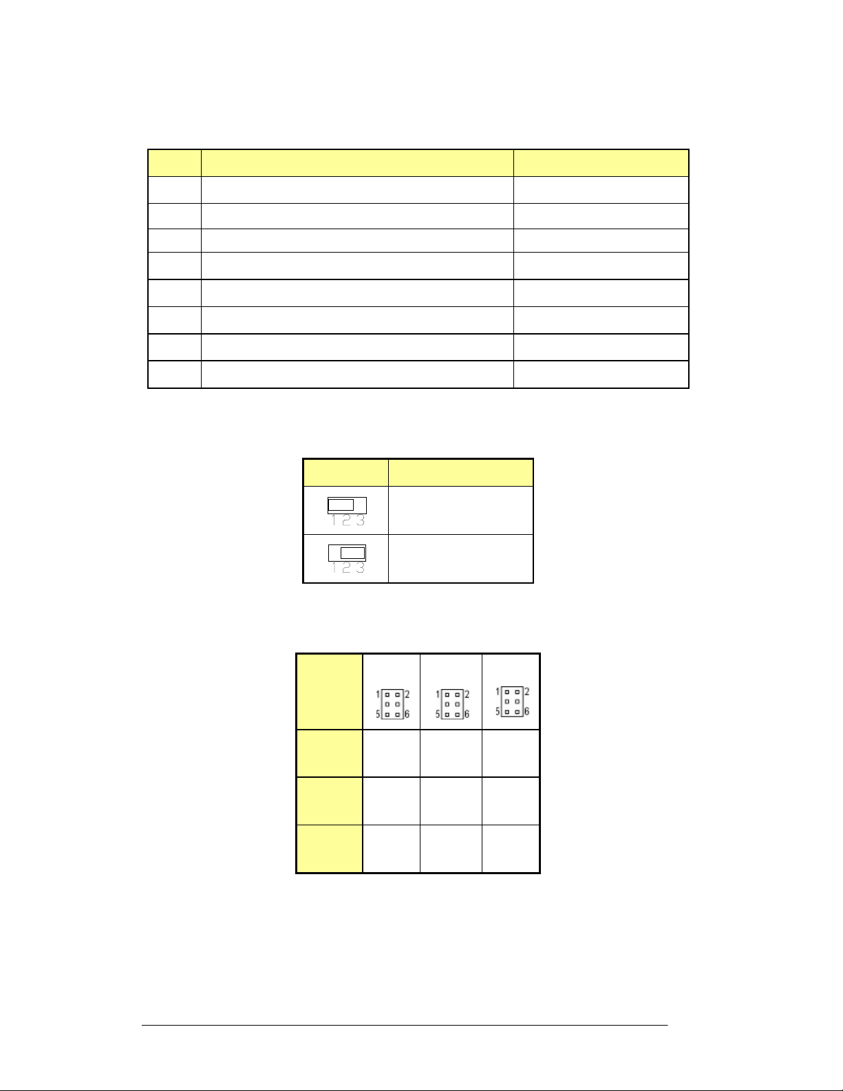
4.3.2 JP2, JP3, JP6 COM2 Select RS232/422/485
JP2
JP3
JP6
RS232
RS485
RS422
1-2
3-5
4-6
3-4
1-3
2-4
5-6
1-3
2-4
3-5
4-6
1-3
2-4
1-3
2-4
Page 22
FPC 71X0
User
Manual
4-14
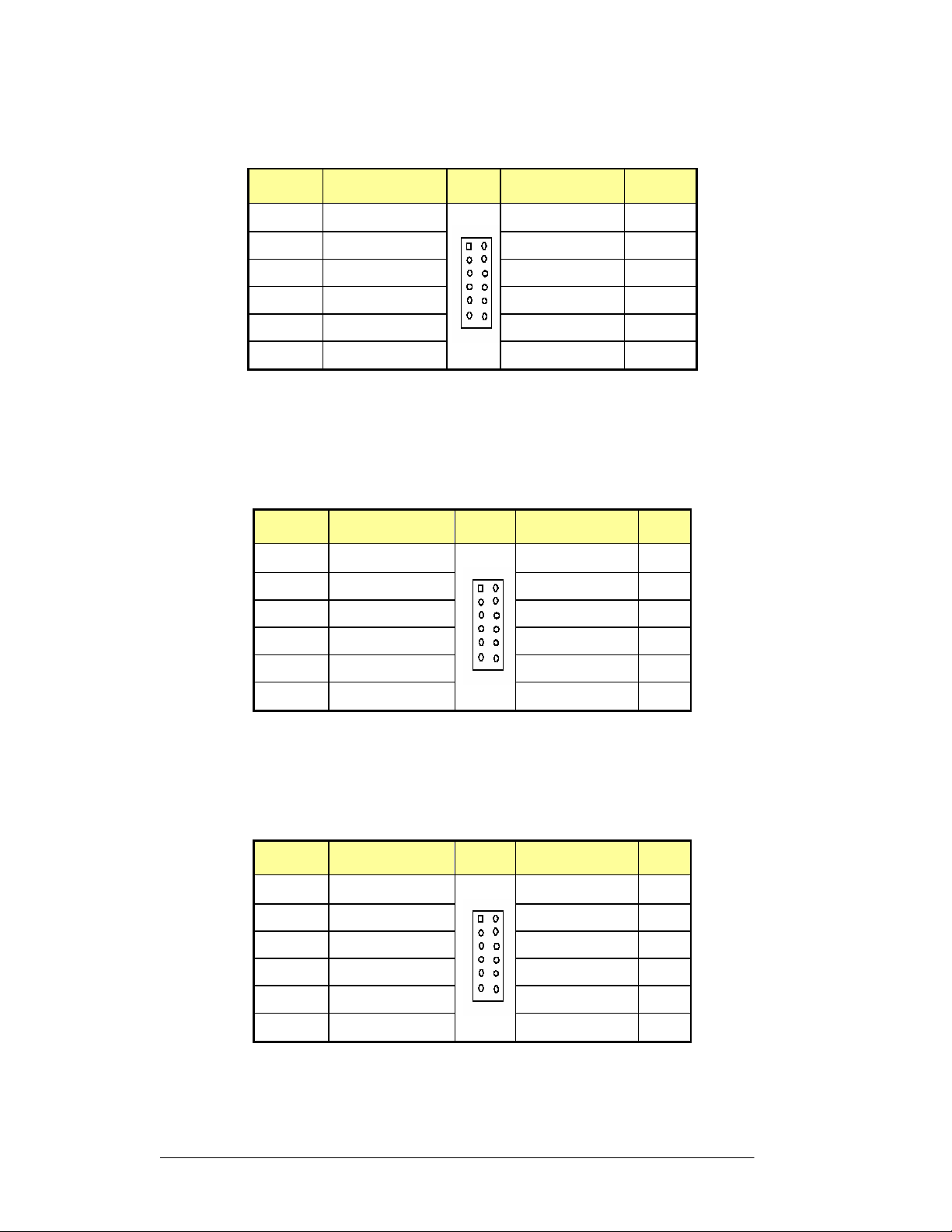
4.3.3
JP4:
COM5, COM6 RS232
+5V/+12V
Power
Se
tting
Pin
Signal Name JP4 Signal Name
Pin
1
3
5
7
9
11
COM5 Settings: Pin 1-2 short= standard COM port, Pin 3-4 short=+12V, Pin 5-6=+5V
COM6 Settings: Pin 7-8 short= standard COM port, Pin 9-10 short=+12V, Pin 11-12=+5V
4.3.4 JP7: COM3, COM4 RS232 +5V/+12V Power Setting
Pin
1
3
5
7
RI (Default)
RI (Default)
Signal Name
RI
RI
RI
RI
RI (Default)
RI
RI
RI (Default)
JP7 Signal Name Pin
RI (Default)
+12v
+5V
RI (Default)
+12V
+5V
RI (Default)
+12v
+5V
RI (Default)
2
4
6
8
10
12
2
4
6
8
+12V
+5V
+12v
+5V
+12V
+5V
10
12
2
4
6
8
10
12
RI
RI
RI
RI
RI
RI
JP8 Signal Name Pin
RI (Default)
RI (Default)
9
11
COM3 Settings: Pin 1-2 short= standard COM port, Pin 3-4 short=+12V, Pin 5-6=+5V
COM4 Settings: Pin 7-8 short= standard COM port, Pin 9-10 short=+12V, Pin 11-12=+5V
4.3.5 JP8: COM1, COM2 RS232 +5V/+12V Power Setting
Pin
Signal Name
1
3
5
7
9
11
COM1 Settings: Pin 1-2 short= standard COM port, Pin 3-4 short=+12V, Pin 5-6=+5V
COM2 Settings: Pin 7-8 short= standard COM port, Pin 9-10 short=+12V, Pin 11-12=+5V
RI (Default)
RI (Default)
Page 23
FPC 71X0
User
Manual
4-15
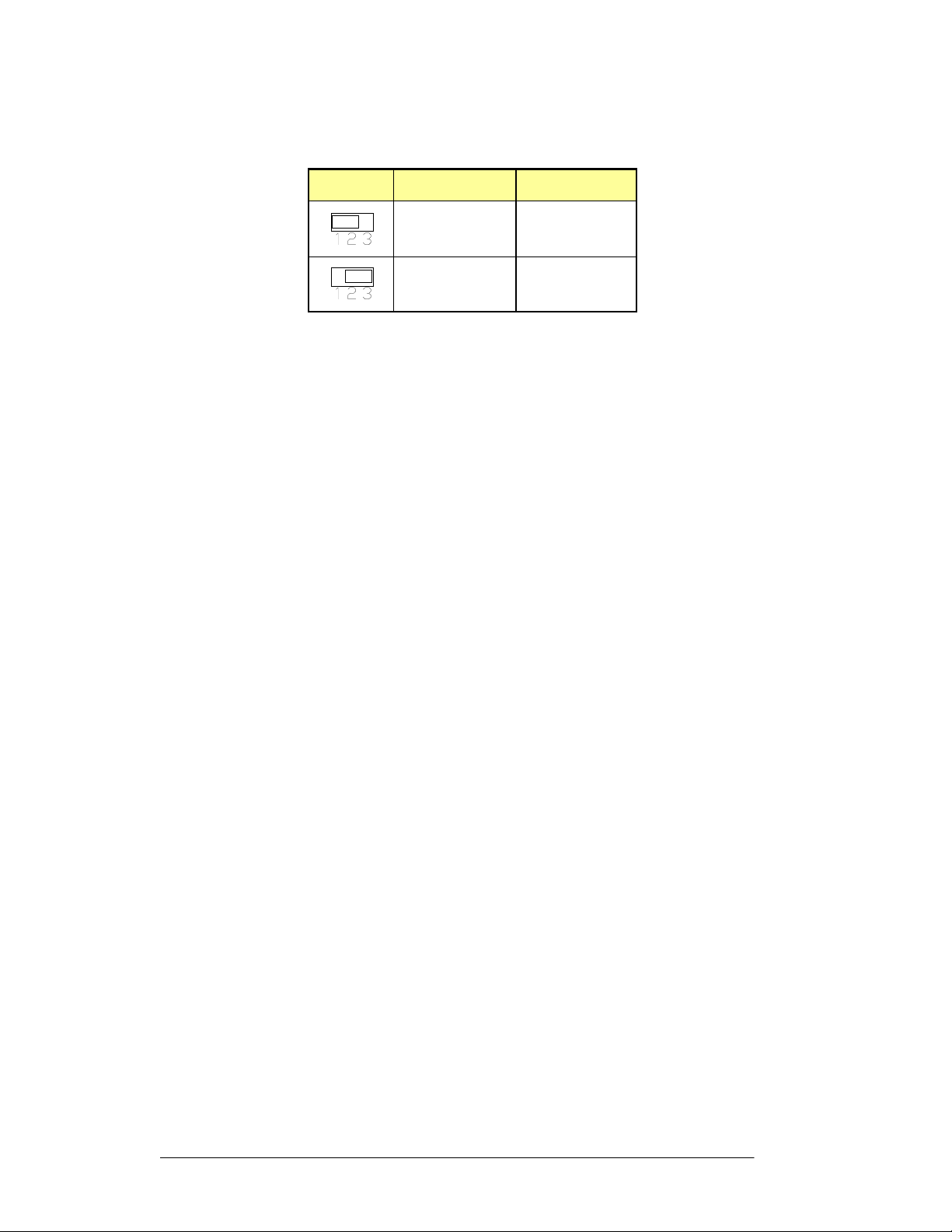
4.3.6
JBT:
Clear
CMOS
Contents
JBT
Note: The DC-12Vpower input connector should be disconnected from the board before
clearing CMOS.
Setting
Pin
1-2
Short/Closed
Pin
2-3
Short/Closed
Function
Normal
Clear CMOS
Page 24

FPC 71X0
User
Manual
4-16
4.4 Connectors and Pin Assignment
The table below lists the function of each of the board’s connectors.
Label
CN1
CN2
CN3
CN4
J1
J2
J3
J4
JP5
LAN1, LAN2
SATA1, ATA2
FAN1, FAN2
Inverter BKL Connector
4 Pin Power Connector
PW/Reset Switch and Indicator Connector
COM3/COM4 D-SUB 9Pin Connector
COM2 + CRT (D-SUB 9Pin+D-SUB 15Pin Connector)
Digital 4-in 4-out I/O Connector
RJ45 + USB0/1, USB2/3 Connectors
CPU Fan Power Connector
Function
USB
Connector
USB
Connector
MSR
Connector
SATA HDD Connector
I_SP
PW_IN
COM1
COM5
COM6
MODEM1
* Not Default Connector
AU1
FDD1
LPT1
LCD1
IDE1
PS1
Internal Speaker Connector
DC Power In (DC12V)
COM Port
COM Port
COM Port
Line Out, Mic Connector
Floppy Drive Connector
Parallel Port (26Pin Header)
LVDS Panel
Onboard Modem Connector
IDE
PS2 Keyboard &Mouse connector
Connector
Connector
Connector
Output
Connector
Page 25

FPC 71X0
User
Manual
4-17
4.4.1
CN1:
Inverter
BKL
Con
nector
Pin
1
Signal Name
Ground
2
3
4
Ground
ENABKL
12V
4.4.2 CN2: 4 Pin Power Output Connector
Pin
1
2
3
4
Signal Name
+12V
GND
GND
+5V
4.4.3 CN3: USB Connectors
The following table shows the pin outs of the USB pin headers connectors. Overall,
the one pin header support four USB ports (USB 2.0 compliant).
Signal Name
Pin Pin
Signal Name
Vcc
USB7-
USB7+
Ground
1
2
3
4
5
6
7
8
Vcc
USB6-
USB6+
Ground
4.4.4 CN4: USB Connectors
The following table shows the pin outs of the USB pin headers connectors. Overall,
one pin header supports four USB ports (USB 2.0 compliant).
Signal Name Pin Pin
Vcc
USB5-
USB5+
Ground
1
3
5
7
2
4
6
8
Signal Name
Vcc
USB4-
USB4+
Ground
Page 26

FPC 71X0
User
Manual
4-18
4.4.5
J1: PW/Reset
Switch
and Indicator
Connect
or
Signal Name Pin Pin
Signal Name
Ground
Ground
IDE_LED-
Power_LED+
LAN_LED-
4.4.6 J2: MSR Connector
6
Note: When MSR is not used, please short jump 2-3 & 5-6 pins.
4.4.7 J3: COM3/COM4 D-SUB 9 Pin Connector
Signal Name
1
Signal Name Pin Pin
+5VSB
KBDATA-OUT
KBCLK-IN
1
3
5
7
9
Pin Pin
2
4
6
8
10
1
3
5
Power_LED-
LAN_LED+
2
4
6
COM3
COM4
PW-ON
Reset_SW
IDE_LED+
Signal Name
Signal Name
KBDATA-IN
Ground
KBCLK-OUT
DCD, Data carrier detect
RXD, Receive data
TXD, Transmit data
DTR, Data terminal ready
Ground
Signal Name
DCD, Data carrier detect
RXD, Receive data
TXD, Transmit data
DTR, Data terminal ready
Ground
1
6
2
7
3
8
4
9
5
Pin Pin
1
6
2
7
3
8
4
9
5
DSR, Data set ready
RTS, Request to send
CTS, Clear to send
RI, Ring indicator
Signal Name
DSR, Data set ready
RTS, Request to send
CTS, Clear to send
RI, Ring indicator
Page 27

FPC 71X0
User
Manual
4-19
4.4.8
J4: COM2+ CRT (D-
SUB
9Pin+D
-
SUB
15Pin
Connector)
Signal Name
DCD, Data carrier detect
RXD, Receive data
TXD, Transmit data
DTR, Data terminal ready
Ground
Signal Name
Red
Green
Blue
NC
Ground
Ground
Ground
Ground
4.4.9 JP5: Digital 4-In 4-Out I/O Connector
Signal Name
Pin Pin
1
Pin Pin
2
3
4
5
1
2
3
4
5
6
7
8
6
7
8
9
9
10
11
12
13
14
15
Pin Pin
Signal Name
DSR, Data set ready
RTS, Request to send
CTS, Clear to send
RI, Ring indicator
Signal Name
+5V
Ground
HSYNC
VSYNC
SPCLK2
Signal Name
NC
SPD2
Ground
Out3
Out2
Int3
Int2
1
2
3
4
5
6
7
8
9
10
Vcc
Out1
Out0
Int1
Int0
Page 28

FPC 71X0
User
Manual
4-20
4.4.10
LAN1,
LAN2:
RJ45
+
USB0/1,
USB2/3
Connectors
4.4.11 SATA1, SATA2: SATA HDD Connector
4.4.12 FAN1, FAN2: CPU Fan Power Connector
FAN1, FAN2 is a 3-pin header for CPU fans. The fan must be a 12V (500mA) fan.
4.4.13 I_SP: Internal Speaker Connector
Pin
Pin
1
1
2
3
Signal Name
Ground
+12V
Rotation detection
Signal Name
SPK_LN
4.4.14 PW_IN: DC Power In (DC12V)
2
3
4
SPK_LO
SPK_RN
SPK_RO
Page 29

FPC 71X0
User
Manual
4-21
4.4.15
COM1: COM
Port
Con
nector
Signal Name
Pin Pin
Signal Name
DCD, Data carrier detect
RXD, Receive data
TXD, Transmit data
DTR, Data terminal ready
Ground
4.4.16 COM5: COM Port Connector
Signal Name
DCD, Data carrier detect
RXD, Receive data
TXD, Transmit data
DTR, Data terminal ready
Ground
4.4.17 COM6: COM Port Connector
Signal Name
1
Pin Pin
Pin Pin
3
5
7
9
10
1
3
5
7
9
10
DSR, Data set ready
2
RTS, Request to send
4
6
8
2
4
6
8
CTS, Clear to send
RI, Ring indicator
No Connect.
Signal Name
DSR, Data set ready
RTS, Request to send
CTS, Clear to send
RI, Ring indicator
No Connect.
Signal Name
DCD, Data carrier detect
RXD, Receive data
TXD, Transmit data
DTR, Data terminal ready
Ground
4.4.18 AU1: Line Out, Mic Connector
1
3
5
7
9
10
DSR, Data set ready
2
RTS, Request to send
4
6
8
CTS, Clear to send
RI, Ring indicator
No Connect.
Page 30

FPC 71X0
User
Manual
4-22
4.4.19 FDD1: Floppy Drive Connector
FDD is a slim 26-pin connector and will support up to 2.88MB FDD.
Signal Name
VCC
VCC
VCC
NC
NC
Pin Pin Signal Name
1
3
5
7
9 10
2
4
6
8
INDEX
DRV_SEL
DSK_CH
MOTOR
NC
4.4.20 LPT1: Parallel Port (26Pin Header)
Signal Name
Line printer strobe
PD0, parallel data0
PD1, parallel data1
PD2, parallel data2
PD3, parallel data3
DINST
NC
GND
GND
GND
NC
GND
GND
11 12
13 14
15 16
17 18
19 20
21 22
23 24
25 26
Pin Pin
1
14
2
15
3
16
4
17
5
18
DIR
STEP
WDATA
WGATE
TRACK
WPROT
RDATA
Signal Name
AutoFeed
Initialize
Ground
SIDE
Error
Select
PD4, parallel data4
PD5, parallel data5
PD6, parallel data6
PD7, parallel data7
ACK, acknowledge
Busy
Paper empty
Select
6
19
7
20
8
21
9
22
10
23
11
24
12
13
25
N/A
Ground
Ground
Ground
Ground
Ground
Ground
Ground
N/A
Page 31

FPC 71X0
User
Manual
4-23
4.4.21
LCD1:
LVDS
Panel
Ou
tput
4.4.22 MODEM1: Onboard Modem Connector
Signal Name
Ground
DCD, Data carrier detect
TXD, Transmit data
DSR, Data set ready
Pin MODEM1 Pin
1
3
5
7
2
4
6
8
Signal Name
Ground
RXD, Receive data
DTR, Data terminal ready
RTS, Request to send
+5V
CTS, Clear to send
NC
MODEM RESET
9
11
13
15
10
12
14
16
RI, Ring indicator
NC
MODEM SP
Ground
Page 32

FPC 71X0
User
Manual
4-24
4.4.23
IDE1:
IDE Connector
Signal Name
Reset IDE
Host data 7
Host data 6
Host data 5
Host data 4
Host data 3
Pin
Pin
Signal Name
1
3
5
7
9
11
2
4
6
8
10
12
Ground
Host data 8
Host data 9
Host data 10
Host data 11
Host data 12
Host data 2
Host data 1
Host data 0
Ground
DRQ0
Host IOW
Host IOR
IOCHRDY
DACK0
IRQ14
Address 1
Address 0
Chip select 0
Activity
Vcc
Ground
4.4.24 PS1: PS2 Keyboard &Mouse connector
Keyboard Signal Pin Mouse Signal
Keyboard data
13
15
17
19
21
23
25
27
29
31
33
35
37
39
41
43
14
16
18
20
22
24
26
28
30
32
34
36
38
40
42
44
Host data 13
Host data 14
Host data 15
Key
Ground
Ground
Ground
Host ALE
Ground
No connect
No connect
Address 2
Chip select 1
Ground
Vcc
N.C.
1
Mouse data
N.C.
GND
5V
Keyboard clock
N.C
2
3
4
5
6
N.C.
GND
5V
Mouse clock
N.C
Page 33

5-25
Chapter 5 A
WARD
BIOS S
ETUP
Power on the computer and immediately press <DEL> to run the AwardBIOS™
CMOS Setup Utility, the setup main menu will appear: The Main Menu allows you to
select from several setup functions and two exit choices. Use the arrow keys to move
among the items and press <Enter> to enter the sub-menu.
5.1 Starting Setup
Award BIOS™ has a built-in setup program that allows users to modify the basic
system configuration. The information is stored in battery-backed Flash so that it
retains the setup information even if the system power is turned off.
Note:
Values for the various setup items that appear on your own screen (including
default values) may not be the same as the values shown on the screen figures
in this chapter. This is because the BIOS is revised and updated from time to
time. If in doubt, check Heisei website for the latest BIOS versions and related
information.
The system BIOS is managing and executing a variety of hardware related
functions in the system, including:
System date and time
Hardware execution sequence
Power management function
Allocation of system resources
FPC 71X0 User Manual
Page 34

FPC 71X0
User M
anual
5-26
5.2 Award BIOS Setup
Power on the computer and immediately press <DEL> to run the AwardBIOS™
CMOS Setup Utility, the setup main menu will appear: The Main Menu allows you to
select from several setup functions and two exit choices. Use the arrow keys to move
among the items and press <Enter> to enter the sub-menu.
Standard CMOS Setup: This page includes all the items in standard
compatible BIOS.
Advanced BIOS Features: This setup page includes all the items of Award
special enhanced features.
Advanced Chipset Features: This setup page includes all the items of chipset
special features.
Integrated Peripherals: This setup page includes all onboard peripherals.
Power Management Setup: This setup page includes all the items of Green
function features.
PnP/PCI Configurations: This option configures how PnP (Plug and Play) and
PCI expansion cards operate in your system.
PC Health Status: This page shows the current system temperature and
voltage.
Frequency/Voltage Control: To set system frequency and voltage control in
this menu.
Load Fail-Safe Defaults: Use this menu to install fail-safe defaults for all
appropriate items in the setup utility.
Load Optimized Defaults: Use this menu to install optimized defaults for all
appropriate items in the setup utility.
Set Supervisor Password: Use this menu option to set the BIOS supervisor
password.
Set User Password: Use this menu option to set the BIOS user password.
Save & Exit Setup: Save CMOS value settings to CMOS and exit setup.
Exit Without Saving: Abandon all CMOS value changes and exit setup.
Page 35

FPC 71X0
User M
anual
5-27
HEISEI
Electronics
Co., Ltd.
5.3 Standard CMOS Features
The standard CMOS features setup allows users to configure system components
such as date, time, hard disk drive, floppy drive and display. Use the arrow keys to
highlight the item and then use the <Page Up> or <Page Down> keys to select the
value you want in each item.
Date (mm : dd : yy)
Set the system date. Note that if you are running a Windows OS, this item is
automatically updated whenever you make changes to the Windows Date.
Time (hh : mm : ss)
The times format in <hour> <minute> <second>. The time is calculated base on
the 24-hour military-time clock. For example, 1 p.m. is 13:00:00.
IDE Channel 0/1 Master/Slave
Press <Enter> to enter the sub-menu to detailed options:
► IDE HDD Auto-Detection
The IDE adapters control the hard disk drive. Use a separate sub-menu to
configure each hard disk drive. Press <Enter> to auto-detect HDD on this
channel. If detection is successful, it fills the remaining fields on this menu.
► IDE Channel 0/1 Master/Slave
Selecting “Manual” lets you set the remaining fields on this screen and
select the type of fixed disk. Options: None, Auto, or Manual.
► Access Mode
Choose the access mode for this hard disk. Options: “CHS”, “LBA”, “Large”,
or “Auto”.
Page 36

FPC 71X0
User M
anual
5-28
HEISEI
Electronics
Co., Ltd.
► Capacity
Note that the disk drive capacity (approx.) is usually slightly greater than the
size of a formatted disk given by a disk-checking program.
► CYLS.
Number of cylinders, Min = 0, Max = 65535
► HEADS
Number of read/write heads, Min = 0, Max = 255
► PRECOMP
Write precomparition, Min = 0, Max =65535.
► LANDZONE
Size of landing zone, Min = 0, Max = 65535.
► SECTORS
Number of sectors per track, Min = 0, Max = 255.
Drive A/B
Set Drive A/B type choice. Options: None”, “360K, 5.25 in.”, “1.2M 5.25 in.”,
“720K, 3.5 in.”, “2.88M, 3.5 in.” or “1.44M, 3.5 in.”.
Video
The category selects the default video device.
Options: EGA/VGA/CGA40/CGA80/Mono
Halt on
This item determines whether the computer will stop if an error is detected during
power up.
Options: “All errors”, “No Errors”, “All, but keyboard”, “All, but Diskette”, or “All,
but Disk/Key”.
Base Memory/Extended Memory/Total Memory
These items are automatically detected by the system at start up time. These are
display-only fields. You cannot make change to these fields.
Page 37
FPC 71X0
User M
anual
5-29
HEISEI
Electronics
Co., Ltd.
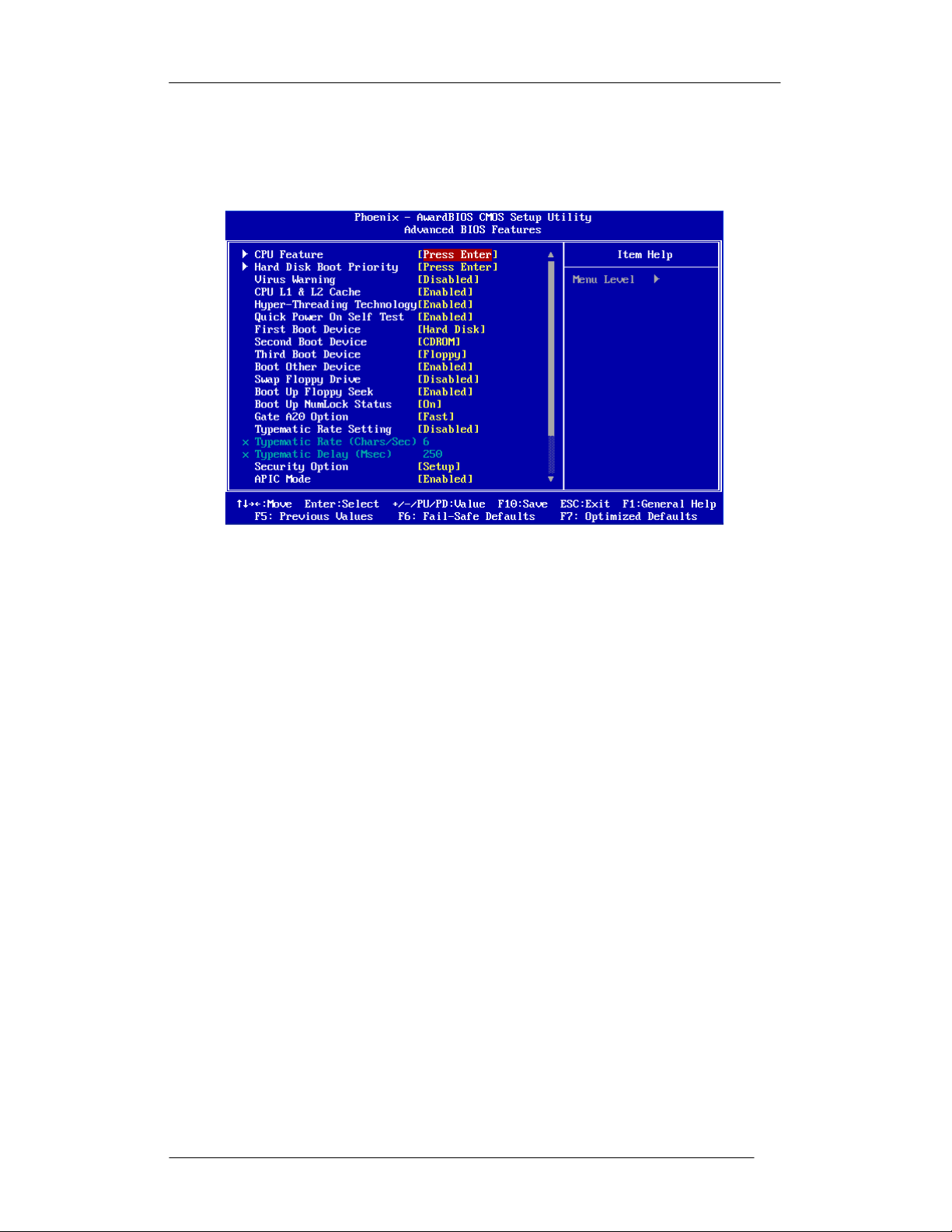
5.4 Advanced BIOS Features
This section allows you to configure your system for basic operation. You can select
the system’s default speed, boot-up sequence, keyboard operation, shadowing and
security.
CPU Feature
The CPU Feature menu is listed below:
► Deplay Prior to Thermal
Options: 4 Min, 8 Min, 16 Min, 32 Min
Default: 16 Min
► Thermal Management
Options: Thermal Monitor 1/2/3
Default: Thermal Monitor 1
► Thermal Monitor Bus Ratio
This item sets the frequency (bus ratio) of the throttled performance that will
be initiated when the on die sensor goes from not hot to hot. You cannot
make change to these items.
► Thermal Monitor Bus VID
This item sets the voltage of the throttled performance that will be initiated
when the on die sensor goes from not hot to hot. You cannot make change to
these items.
Hard-Disk Boot Priority
This is for setting the priority of the hard disk boot order when the “Hard Disk”
option is selected in the “[First/Second/Third] Boot Device” menu item. You can
change the priority on the List.
Page 38

FPC 71X0
User M
anual
5-30
HEISEI
Electronics
Co., Ltd.
Virus Warning
Allow you to choose the Virus Warning feature for IDE Hard Disk boot sector
protection. Enable this item to prevent someone from writing data into this area.
Options: Enabled or Disabled
Default: Disabled
CPU L1 & L2
All processors that can be installed in this motherboard use internal level of L1
cache memory to improve performance. Leave this item at the default value for
better performance.
Options: Enabled or Disabled
Default: Enabled
Cache
CPU L2 Cache ECC Checking
This feature enables or disables the L2 (Level 2 or Secondary) cache's ECC
checking function.
Options: Enabled or Disabled
Default: Enabled
Quick Power On Self Test
Enable this item to shorten the power on testing (POST) and have your system
start up faster. You might like to this item after you are confident that your system
hardware is operating smoothly.
Options: Enabled or Disabled
Default: Enabled
First/Second/Third Boot Device
Set the boot device sequence as BIOS attempts to load the disk operating system.
Options: Floppy, LS120, Hard Disk, CDROM, ZIP100, USB-FDD, USB-ZIP or
USB-CDROM.
Default: Hard Disk (First) / CDROM (Second) / Floppy (Third)
Boot Other Device
If you enable this item, the system searches all other possible locations for and
operating system if it fails to find one in the devices specified under the First,
Second and the Third boot devices.
Options: Enabled or Disabled
Default: Enabled
Page 39

FPC 71X0
User M
anual
5-31
HEISEI
Electronics
Co., Ltd.
Boot Up Num Lock
Status
This item defines if the keyboard Num Lock key is active when your system is
started.
Options: On or Off
Default: On
Typematic Rate Setting
This Enables “Typematic Rate” and “Typematic Delay” functions.
Options: Enabled, Disabled
Default: Disabled
Typematic Rate (Chars/Sec)
This item sets the rate (characters/second) at which the system retrieves a signal
from a depressed key.
Options: 6, 8, 10, 12, 15, 20, 24, 30
Default: 6
Typematic Delay (Msec)
This item sets the delay between when the key was first pressed and when the
system begins to repeat the signal from the depressed key.
Options: 250, 500, 750, 1000
Default: 250
Security Option
Options: Setup or System
Default: Setup
MPS Version Control For OS
Options: 1.1 or 1.4
Default: 1.4
OS Select For DRAM > 64MB
Options: Non-OS2 or OS2
Default: Non-OS2
Small Logo (EPA) Show
Options: Enabled or Disabled
Default: Disabled
Page 40

FPC 71X0
User M
anual
5-32
HEISEI
Electronics
Co., Ltd.
5.5 Advanced Chipset Features
These items define critical timing parameters of the mainboard. You should leave the
items at their default values unless you are very familiar with the technical,
specifications of the system hardware. If you change the values incorrectly, you may
introduce fatal error or recurring instability into your system.
DRAM Clock/Drive Control
► System Memory Frequency
The chipset supports synchronous and asynchronous mode between host
clock and DRAM clock frequency.
Options: Auto, 533MHz, 667 MHz
Default: Auto
► DRAM Timing
The value in this field depends on the memory modules installed in your
system. Changing the value from the factory setting is not recommended
unless you install new memory that has a different performance rating than
the original modules.
Options: Manual, By SPD
Default: By SPD
Memory Hole At 15-16M
Options: Disabled or Enable
Default: Disabled
System BIOS Cacheable
Options: Enabled or Disabled
Default: Enabled
Page 41

FPC 71X0
User M
anual
5-33
HEISEI
Electronics
Co., Ltd.
Video RAM Cacheable
Options: Enabled or Disabled
Default: Disabled
Page 42

FPC 71X0
User M
anual
5-34
HEISEI
Electronics
Co., Ltd.
5.6 Integrated Peripherals
OnChip IDE Device
► IDE DMA transfer access
Options: Enabled, Disabled
Default: Enabled
► OnChip IDE
Options: Enabled, Disabled
Default: Enabled
► Secondary Master PIO
Options: Auto, Mode 0, Mode 1, Mode 2, Mode 3, Mode 4
Default: Auto
► Secondary Slave
Options: Auto, Mode 0, Mode 1, Mode 2, Mode 3, Mode 4
Default: Auto
channel1
► Secondary Master UDMA
Options: Disabled, Auto
Default: Auto
► Secondary Slave UDMA
Options: Disabled, Auto
Default: Auto
► IDE HDD Block Mode
Options: Enabled, Disabled
Default: Enabled
PIO
Page 43

FPC 71X0
User M
anual
5-35
HEISEI
Electronics
Co., Ltd.
Super IO Device
► Onboard FDC Controller
Options: Enabled, Disabled
Default: Enabled
► Onboard Serial Port 1
Options: Disabled, 3F8/IRQ4, 2F8/IRQ3, 3E8/IRQ4, 2E8/IRQ3, Auto
Default: 3F8/IRQ4
► Onboard Serial Port 2
Options: Disabled, 3F8/IRQ4, 2F8/IRQ3, 3E8/IRQ4, 2E8/IRQ3, Auto
Default: 2F8/IRQ3
► UART Mode Select
Options: IrDA, ASKIR, Normal
Default: Normal
► Onboard Parallel Port
Options: Disabled, 378/IRQ7, 278/IRQ5, 3BC/IRQ7
Default: 378/IRQ7
► Parallel Port Mode
Options: SPP, EPP, ECP, ECP/EPP, Normal
Default: SPP
Onboard Serial Port 3
This option is used to assign the I/O address and Interrupt Request (IRQ) for the
onboard Serial Port.
Options: 280, 288, 2A0, 2A8
Default: 280
Page 44

FPC 71X0
User M
anual
5-36
HEISEI
Electronics
Co., Ltd.
Serial Port 3 Use IRQ
Options: IRQ5, IRQ7, IRQ10, IRQ11
Default: IRQ10
Onboard Serial Port 4
This option is used to assign the I/O address and Interrupt Request (IRQ) for the
onboard Serial Port.
Options: 280, 288, 2A0, 2A8
Default: 288
Serial Port 4 Use IRQ
Options: IRQ5, IRQ7, IRQ10, IRQ11
Default: IRQ10
Onboard Serial Port 5
This option is used to assign the I/O address and Interrupt Request (IRQ) for the
onboard Serial Port.
Options: 280, 288, 2A0, 2A8
Default: 2A0
Serial Port 5 Use IRQ
Options: IRQ5, IRQ7, IRQ10, IRQ11
Default: IRQ10
Onboard Serial Port 6
This option is used to assign the I/O address and Interrupt Request (IRQ) for the
onboard Serial Port.
Options: 280, 288, 2A0, 2A8
Default: 2A8
Serial Port 6 Use IRQ
Options: IRQ5, IRQ7, IRQ10, IRQ11
Default: IRQ10
Page 45

FPC 71X0
User M
anual
5-37
HEISEI
Electronics
Co., Ltd.
USB Device Setting
► USB Controller
Enable or disable Universal Host Controller Interface for Universal Serial
Bus.
Options: Enabled, Disabled
Default: Enabled
► USB 2.0
Controller
Enable or disable Enhanced Host Controller Interface for Universal Serial
Bus.
Options: Enabled, Disabled
Default: Enabled
► USB Keyboard Function
Enable or disable Legacy support of USB Keyboard
Options: Enabled, Disabled
Default: Enabled
► USB Mouse
Function
Enable or disable Legacy support of USB Mouse
Options: Enabled, Disabled
Default: Enabled
► USB Storage Function
Enable or disable Legacy support of USB Mass Storage
Options: Enabled, Disabled
Default: Enabled
► Azalia/AC97 Audio Select
Options: Auto, All Disabled
Default: Auto
Page 46

FPC 71X0
User M
anual
5-38
HEISEI
Electronics
Co., Ltd.
5.7 Power Management Setup
ACPI function
Options: Disabled, Enabled
Default: Enabled
ACPI Suspend Type
Options: S1 (POS), S3 (STR), S1 & S3
Default: S1 (POS)
S1/Power on suspend (POS) is a low power state. In this state, no system context
(CPU or chipset) is lost and hardware maintains all system contexts. S3/Suspend
to RAM (STR) is a power-down state. In this state, power is supplied only to
essential components such as main memory and wakeup-capable devices. The
system context is saved to main memory, and context is restored from the
memory when a "wakeup" event occurs. The S1 & S3 option is depends on the
OS to select S1 or S3.
Power Management Option
Options: User Define, Min Saving, Max Saving
Default: User Define
HDD Power Down
Sets the length of time for a period of inactivity before the hard disk power down.
Options: Disabled, 1~15 (minutes)
Default: Disabled
Page 47

FPC 71X0
User M
anual
5-39
HEISEI
Electronics
Co., Ltd.
Suspend Mode
Options: Disabled, 1 Min, 2 Min, 4 Min, 6 Min, 8 Min, 10 Min, 20 Min, 30 Min, 40
Min, 1 Hour
Default: Disabled
Video Off Method
Options: Blank Screen, V/H SYNC+ Blank, DPMS Support
Default: V/H SYNC+ Blank
Video Off In Suspend
Options: Yes, No
Default: Yes
Soft-Off by PWR-BTTN
System is turned off if power button is pressed for more than four seconds, or
Power button functions as a normal power-on/-off button.
Options: Delay 4 Sec, Instant-Off
Default: Delay 4 Sec
Page 48

FPC 71X0
User M
anual
5-40
HEISEI
Electronics
Co., Ltd.
5.8 PnP/PCI Configuration
Reset Configuration Data
Enabled will reset the ESCD (Extended System Configuration Data) after exiting
BIOS Setup if a newly installed PCI card or the system configuration prevents the
operating system from loading. This field should usually be left “Disabled”.
Options: Enabled, Disabled
Default: Disabled
Resources Controlled By
Enables the BIOS to automatically configure all the Plug-and-Play compatible
Devices, e.g. assign IRQ, DMA and memory base address fields. Or manually
Unlocks “IRQ Resources” for manual configuration.
Options: Auto (ESCD), Manual
Default: Auto (ESCD)
Page 49

FPC 71X0
User M
anual
5-41
HEISEI
Electronics
Co., Ltd.
5.9 Frequency/Voltage Control
Auto Detect PCI Clk
Options: Disabled, Enabled
Default: Enabled
Spread Spectrum
When the mainboard's clock generator pulses, the extreme values (spikes) of the
pulses create EMI (Electromagnetic Interference). The Spread Spectrum function
reduces the EMI generated by modulating the pulses so that the spikes of the
pulses are reduced to flatter curves.
Options: Disabled, Enabled
Default: Disabled
Page 50

FPC 71X0
User M
anual
5-42
HEISEI
Electronics
Co., Ltd.
5.10 Load Fail-Safe Defaults
When you press <Enter> on this item, you will get confirmation dialog box with a
message similar to:
Load Fail-Safe Defaults (Y/N)? N
Pressing ‘Y’ loads the BIOS default values for the most stable, minimal
performance system operations.
This option is for restoring all the default fail-safe BIOS settings. These values are set
by the mainboard manufacturer to provide a stable system with basic performance.
Page 51

FPC 71X0
User M
anual
5-43
HEISEI
Electronics
Co., Ltd.
5.11 Load Optimized Defaults
When you press <Enter> on this item, you will get confirmation dialog box with a
message similar to:
Load Optimized Defaults (Y/N)? N
Pressing ‘Y’ loads the default values that are factory-set for optimal
performance system operation.
This option is for restoring all the default optimized BIOS settings. The default
optimized values are set by the mainboard manufacturer to provide a stable system
with optimized performance.
Page 52

FPC 71X0
User M
anual
5-44
HEISEI
Electronics
Co., Ltd.
5.12 Set Supervisor/User Password
Steps to set supervisor/user password are described as
New password setting:
1. While pressing <Enter> to set a password, a dialog box appears to ask
you enter a password.
follows:
2. Key in a new password. The password cannot exceed eight
characters.
Please Enter Your Password
3. System will request you to confirm the new password again.
Please Confirm Your
4. When completed, new code takes effect.
No Password Setting:
If you wants to disable the password, just <Enter> as a password input is
requested.
If you forget password:
If you forget the password, the only way to access the system is to clear the
CMOS memory. You may remove the battery from motherboard and put it
back to clear the setting.
Password
Page 53
FPC 71X0
User M
anual
5-45
HEISEI
Electronics
Co., Ltd.
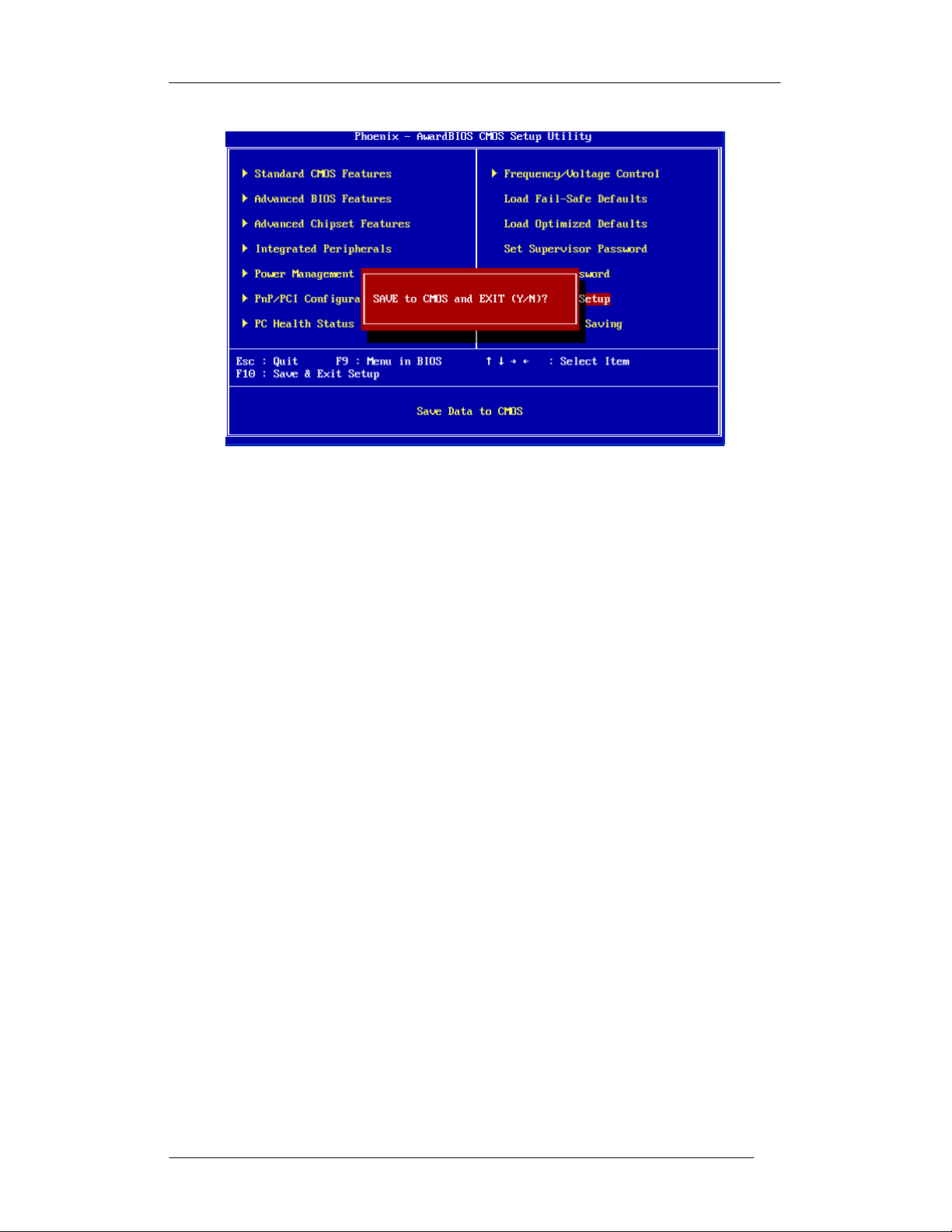
5.13 Save & Exit Setup
Pressing <Enter> on this item asks for confirmation:
Save to CMOS and Exit (Y/N)? Y
Press ‘Y’ stores the selections made in the menus of CMOS – a special
section of memory that recorded in after you turn your system off. The
next time you turn on your computer, the BIOS configures your system
according to the Setup selections recorded in he CMOS memory of the
chipset. After saving the values the system is restarted again.
Page 54

FPC 71X0
User M
anual
5-46
5.14 Exit Without Saving
Press <Enter> on this item asks for confirmation:
Quit Without Saving (Y/N)? Y
This allows you to exit from Setup without storing in CMOS any change. The
previous selections remain in effect. This exits from Setup utility and restarts
your computer.
Page 55

FPC
71X0
User M
anual
6-47
Chapter 6 D
RIVERS INSTALLATION
This chapter offers information of software drivers’ installation.
6.1 Chipset Driver Installation
The FPC 71X0 series chipset Drivers should be installed first before the software
drivers to enable Plug & Play INF support for FPC 71X0 series chipset components.
Follow the instructions below to complete the installation.
6.1.1 Windows XP
A. Click the folder “Chipset”. B. Click “Setup” to install.
C. Click Next. D. Click “Yes” to accept the agreement.
Page 56

FPC
71X0
User M
anual
6-48
E. Click Next. F. Click “Next” to go on.
G. Select “Yes, I want to restart the
computer now.”, and click Finish.
6.1.2 Windows VISTA
A. Click the folder “Chipset”. B. Click “Setup” to install.
Page 57

FPC
71X0
User M
anual
6-49
C. Click Next. D. Click Yes to accept the agreement.
E. Click Next. F. Click Next.
G. Select “Yes, I want to restart the
computer now.”, and click Finish.
Page 58

FPC
71X0
User M
anual
6-50
6.1.3 Windows POSReady 2009
A. Click the folder “Chipset”. B. Click “Setup” to install.
C. Click Next. D. Click Yes to accept the agreement.
E. Click Next. F. Change the path “C:\WINDOWS\
system32\drivers” and click OK.
Page 59

FPC
71X0
User M
anual
6-51
G. Change the path “C:\WINDOWS\ H. Change the path “C:\WINDOWS\
system32\drivers” and click OK. system32\drivers” and click OK.
I. Change the path “C:\WINDOWS\ J. Change the path “C:\WINDOWS\
system32\drivers” and click OK. system32\drivers” and click OK.
K. Change the path “C:\WINDOWS\ L. Change the path “C:\WINDOWS\
system32\drivers” and click OK. system32\drivers” and click Retry.
M. Change the path “C:\WINDOWS\ N. Change the path “C:\WINDOWS\
system32\drivers” and click OK. system32\drivers” and click Retry.
Page 60

FPC
71X0
User M
anual
6-52
O. Change the path “C:\WINDOWS\ P. Change the path “C:\WINDOWS\
system32\drivers” and click OK. system32\drivers” and click Retry.
Q. Change the path “C:\WINDOWS\ R. Change the path “C:\WINDOWS\
system32\drivers” and click OK. system32\drivers” and click Retry.
S. Change the path “C:\WINDOWS\ T. Change the path “C:\WINDOWS\
system32\drivers” and click OK. system32\drivers” and click Retry.
U. Click Next. V. Click Finish to complete the process.
Page 61

FPC 71X0
User M
anual
6-53
6.2 Ethernet Driver Installation
The FPC 71X0 series is equipped with the Realtek RTL8111B Ethernet
combines
a triple-speed IEEE 802.3 compliant Media Access Controller (MAC) with a
triple-speed Ethernet transceiver, PCI Express bus controller, and embedded memory.
With state-of-the-art DSP technology and mixed-mode signal technology, it offers
high-speed transmission over CAT 5 UTP cable or CAT 3 UTP (10Mbps only) cable.
Follow the installation steps for Windows XP/VISTA/POSReady 2009.
6.2.1 Windows XP
controller
A. Click the folder “LAN”. B. Click the folder “Win2k_xp”.
C. Click “RTL8168_8101E_664”. D. Click “setup” to install.
Page 62

FPC 71X0
User M
anual
6-54
E. Click Next. F. Click Install to start.
G. Click Finish to complete the process.
6.2.2 Windows VISTA
A. Click the folder “LAN”. B. Click the folder “Vista”.
Page 63

FPC 71X0
User M
anual
6-55
C. Click “Vista_RTL8168_8101E_8169_ D. Click “setup” to install.
6193_070606”.
E. Click Next. F. Click Install to start.
G. Click Finish to complete.
Page 64

FPC 71X0
User M
anual
6-56
6.2.3 Windows POSReady 2009
A. Click the folder “LAN”. B. Click the folder “Win2k_xp”.
C. Click “RTL8168_8101E_664”. D. Click “setup” to install.
E. Click Next. F. Click Install.
Page 65

FPC 71X0
User M
anual
6-57
G. Click Finish to complete.
Page 66

FPC 71X0
User Manual
6-58
6.3 VGA Driver Installation
The FPC 71X0 series offers an integrated VGA/LCD Controller, 2D/3D GUI engine,
sharing memory architecture up to 64 MB. The specifications and features are
described as follows: The FPC 71X0 series supports CRT and TFT LCD displays. In
addition, it also supports CRT and flat panel display mode simultaneously. The FPC
71X0 series can be set in one of three configurations: on a CRT, on a flat panel
display,
mode. Follow the installation steps for Windows XP/VISTA/POSReady 2009.
or on
both simultaneously. The system is initially set to simultaneous display
6.3.1 Windows XP
A. Click the folder “VGA”. B. Click the folder “win2k_xp”.
C. Click “Setup” to install. D. Click Next.
Page 67

FPC 71X0
User M
anual
6-59
E. Click Yes to accept the agreement. F. Click Next.
G. Click Next to go on. H. Click Finish to complete the process.
6.3.2 Windows VISTA
A. Click the folder “VGA”. B. Click the folder “VISTA”.
Page 68

FPC 71X0 User Manual
6-60
C. Click “winvista_1583” to install. D. Click Next.
E. Click Next. F. Click Yes.
G. Click Next. H. Click Next to go on.
Page 69

FPC 71X0 User Manual
6-61
I. Click Finish.
6.3.3 Windows POSReady 2009
A. Click the folder “VGA”. B. Click the folder “win2k_xp”.
C. Click “Setup” to install. D. Click Next.
Page 70

FPC 71X0 User Manual
6-62
E. Click Yes to accept the agreement. F. Click Next.
G. Click Next. H. Click Finish to complete the process.
Page 71

FPC 71X0 User Manual
6-63
6.4 Audio Driver Installation
The FPC 71X0 series is equipped with the VIA HD Codec VT1708A, which is
delivering top quality audio performance, supporting the latest 8-channel, 24-bit,
192KHz audio content for an all-round high fidelity experience. Integrating stereo
DACs with a 100dB S/N ratio and compliant with the Intel® High Definition Audio Rev.
1.0 specification. Follow the installation steps for Windows XP/VISTA/POSReady
2009.
6.4.1 Windows XP
A. Click the folder “AUDIO”. B. Click the folder “XP”.
C. Click the folder “v560a”. D. Click “SETUP” to install.
E. Click Next. F. Select “I Agree” and click Next.
Page 72

FPC 71X0 User Manual
6-64
G. Click Next. H. Click Next to continue.
I. Click Next. J. Click Finish.
6.4.2 Windows VISTA
A. Click the folder “AUDIO”. B. Click the folder “Vista”.
Page 73

FPC 71X0 User Manual
6-
65
C. Click the folder “v340f”. D. Click “SETUP” to install.
E. Click Next. F. Select “I Agree” and click Next.
G. Click Next. H. Click Next.
Page 74

FPC 71X0 User Manual
6-
66
I. Click Next to continue. J. Click Finish.
6.4.3 Windows POSReady 2009
A. Click the folder “AUDIO”. B. Click the folder “XP”.
C. Click the folder “v560a”. D. Click “SETUP” to install.
Page 75

FPC 71X0 User Manual
6-
67
E. Click Next. F. Click I Agree and click Next.
G. Click Next. H. Click Next.
I. Change the path “C:\WINDOWS\ J. Change the path “C:\WINDOWS\
system32” and click OK. system32\drivers” and click Retry.
Page 76

FPC 71X0 User Manual
6-
68
K. Click Next. L. Click Finish to complete the process.
Page 77

FPC 71X0 User Manual
6-69
6.5 Wireless LAN Driver Installation
The Users must make sure which operating system you are using in the FPC 71X0
series before installing the Wireless LAN drivers. Follow the steps below to complete
the installation. You will quickly complete the installation. Follow the installation steps
for Windows XP/VISTA/POSReady 2009.
A. Click the file “Ralink_RT73 “ B. Click Finish to complete the process.
C. The screen will show the RaUI window.
Page 78

FPC 71X0 User manual
6-70
6.6 Touch Driver Installation
The FPC 71X0 series supports HIGGSTEC Touch. The touchscreen systems consist
of a touchscreen and an electronic touchscreen controller.
A. Click the folder “Touch”. B. Click “All_In_One_2k_XP_Vista”.
C. Click “setup” to install driver. D. Click Next to continue.
E. Click Next. F. Click Next.
Page 79

6-71
G. Click OK. H. Click Next.
I. Click Next. J. Click Next.
K. Click Yes. L. Click Yes.
FPC 71X0 User manual
Page 80
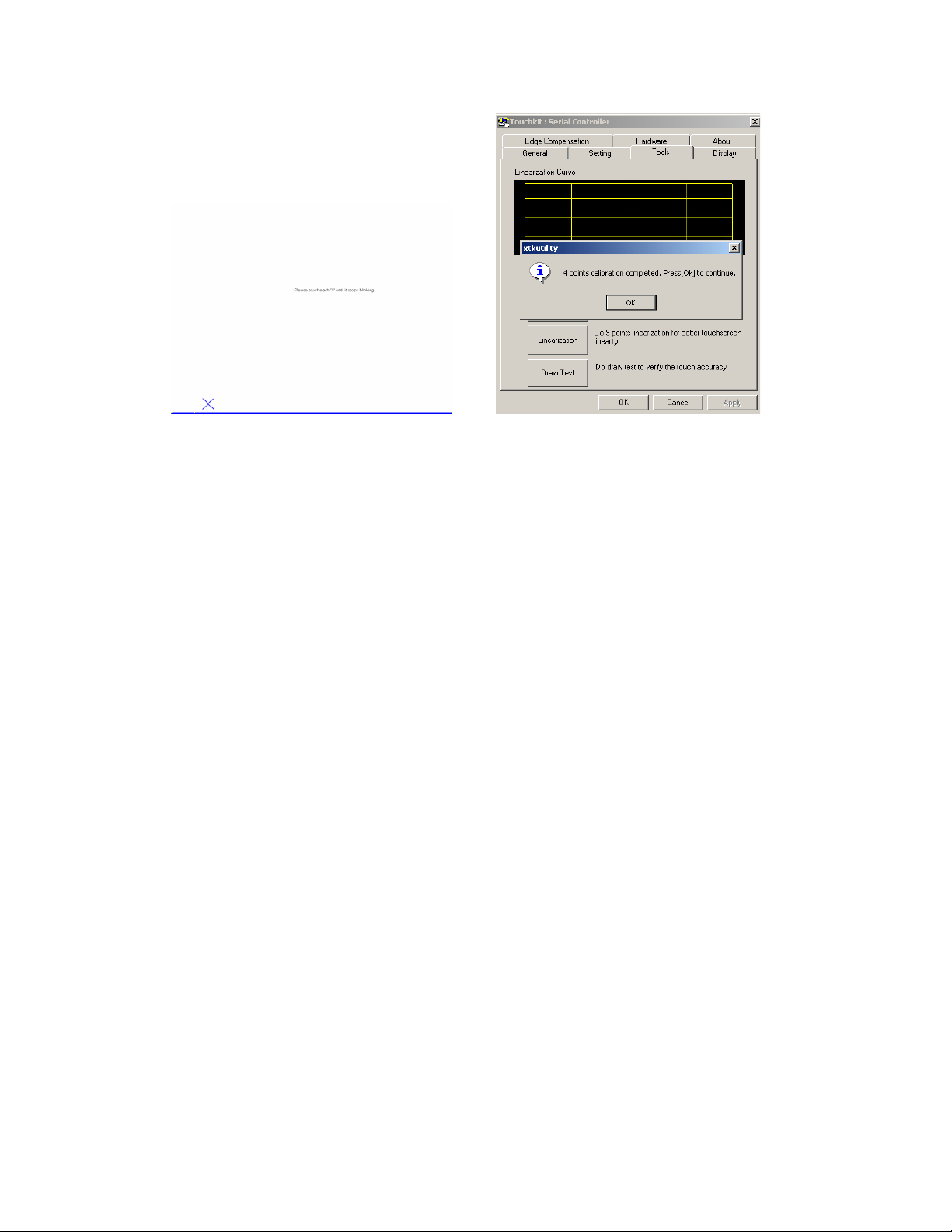
6-72
M. Press the blinking X Symbol until stop N. Click OK to complete the process.
blinking.
FPC 71X0 User manual
 Loading...