

Page 1

User Manual
FPC1012/1015: 12/15” Industrial Fanless Panel PC with
Atom D2550 Dual Core Processor
FPC1012/1015
12/15 inch Atom Fanless Panel PC
14628 Ce ntral Ave,
Chino , CA 91710
tel:909.597.7 588, fax:909.597.1939
© Copyright 2013 Acnodes, Inc.
All righ ts reserved. Product descripti on and product speci ficat ions
are subj ect to change w ith out n oti ce. F or lates t product inform ati on,
ple ase vis it Acnod es’ we b site at www.ac nodes.c om.
Page 2

FPC1012/1015
No part of this manual, including the products and software de scribed in it, ma y be
reproduced, transmitted, transcribed, stored in a retrieval system, or translated into
any language in any form or by any m eans, except documentation kept by the
purchaser for backup purposes, witho ut the express written permission of Acno des
Corporation .
Products and corporate names mentioned in this manual may or may n ot b e
registered trademarks or copyrights of their respective companies, and are used for
identification purposes only. All trademarks are the property of their respective
owners.
Every effort has been made to ensure that the contents of this manual are correct and
up to date. However, the man ufacturer makes no gua rantee regarding the accuracy of
its conten ts, and reserves the right to make changes without prior notice.
12/15 inch Atom Fanless Panel PC
14628 Ce ntral Ave,
Chino , CA 91710
tel:909.597.7 588, fax:909.597.1939
© Copyright 2013 Acnodes, Inc.
All right s reser ved . Produc t descr ipt ion and product speci fi cat io ns
are subj ect to change w ith out n oti ce. F or lates t product inform ati on,
ple ase vis it Acnod es’ we b site at www.ac nodes.c om.
Page 3

Components
Front side
FPC1015
Auto-dimming sensor
(FPC1015 only)
Function Key 2
(FPC1015 only)
Function Key 1
FPC1012
Function Key 1
Page 4

Function key
Function Key 2 Function Key 1
Home (browser)
E-mail
Play/Pause
Volume control
Power Button
Page Up
LCD Brightness control
Page D own
IO side
Refer to the diagram b elow to identify the comp onents on this side of the system.
RS-232/422/485 PCI slot
12V DC-in
VGA
LAN1 LAN2
Mic-in
Line-out USB GPIO
Page 5

Top View
Speaker
(FPC1015 only)
Page 6

Installation
Installing Panel Mount
Screw
Panel mount body
1. To assemb ly screw and panel mount body and put on the rubber cap at screw
bottom as above picture.
2. Put th e Panel PC into the wall.
FPC1012/1015
12/15 inch Atom Fanless Panel PC
14628 Ce ntral Ave,
Chino , CA 91710
tel:909.597.7 588, fax:909.597.1939
© Copyright 2013 Acnodes, Inc.
All right s reser ved . Produc t descr ipt ion and product speci fi cat io ns
are subj ect to change w ith out n oti ce. F or lates t product inform ati on,
ple ase vis it Acnod es’ we b site at www.ac nodes.c om.
Page 7

B
C
A
D
E
3. Put the panel mount from A to E
Page 8

FPC1012/1015
4. Lock the each screw of the panel mount.
12/15 inch Atom Fanless Panel PC
14628 Ce ntral Ave,
Chino , CA 91710
tel:909.597.7 588, fax:909.597.1939
© Copyright 2013 Acnodes, Inc.
All right s reser ved . Produc t descr ipt ion and product speci fi cat io ns
are subj ect to change w ith out n oti ce. F or lates t product inform ati on,
ple ase vis it Acnod es’ we b site at www.ac nodes.c om.
Page 9

FPC1012/1015
Installing VESA mount
B
A
D
C
1. VESA mount of Panel PC is comp atible with VESA stand 75x75 and
100x100
2. Put your VESA mount Kit on the R ed Area.
3. Lock the screws from A to D.
12/15 inch Atom Fanless Panel PC
14628 Ce ntral Ave,
Chino , CA 91710
tel:909.597.7 588, fax:909.597.1939
© Copyright 2013 Acnodes, Inc.
All righ ts reserved. Product descripti on and product speci ficat ions
are subj ect to change w ith out n oti ce. F or lates t product inform ati on,
ple ase vis it Acnod es’ we b site at www.ac nodes.c om.
Page 10
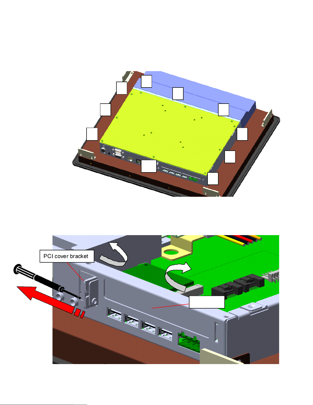
Installing PCI module
1. Unlock and remove screws from point 1 to point 10
2. Remove the back cover (a Ye llow part) from PPC controller.
4
3
5
2 6
1 7
8
10
9
3. Unlock and Remo ve a screw from PCI slot cover.
4. Remove PCI cover and PCI cover bracket from inside.
PCI cover bracket
PCI cover
Page 11

FPC1012/1015
5. Install your PCI add-on card. (red circle are PCI slots)
6. Put on the PCI cover bracket and lock the screw.
7. Put on the back cover and lock screws to finish the PCI add-on card installation.
12/15 inch Atom Fanless Panel PC
14628 Ce ntral Ave,
Chino , CA 91710
tel:909.597.7 588, fax:909.597.1939
© Copyright 2013 Acnodes, Inc.
All righ ts reserved. Product descripti on and product speci ficat ions
are subj ect to change w ith out n oti ce. F or lates t product inform ati on,
ple ase vis it Acnod es’ we b site at www.ac nodes.c om.
Page 12
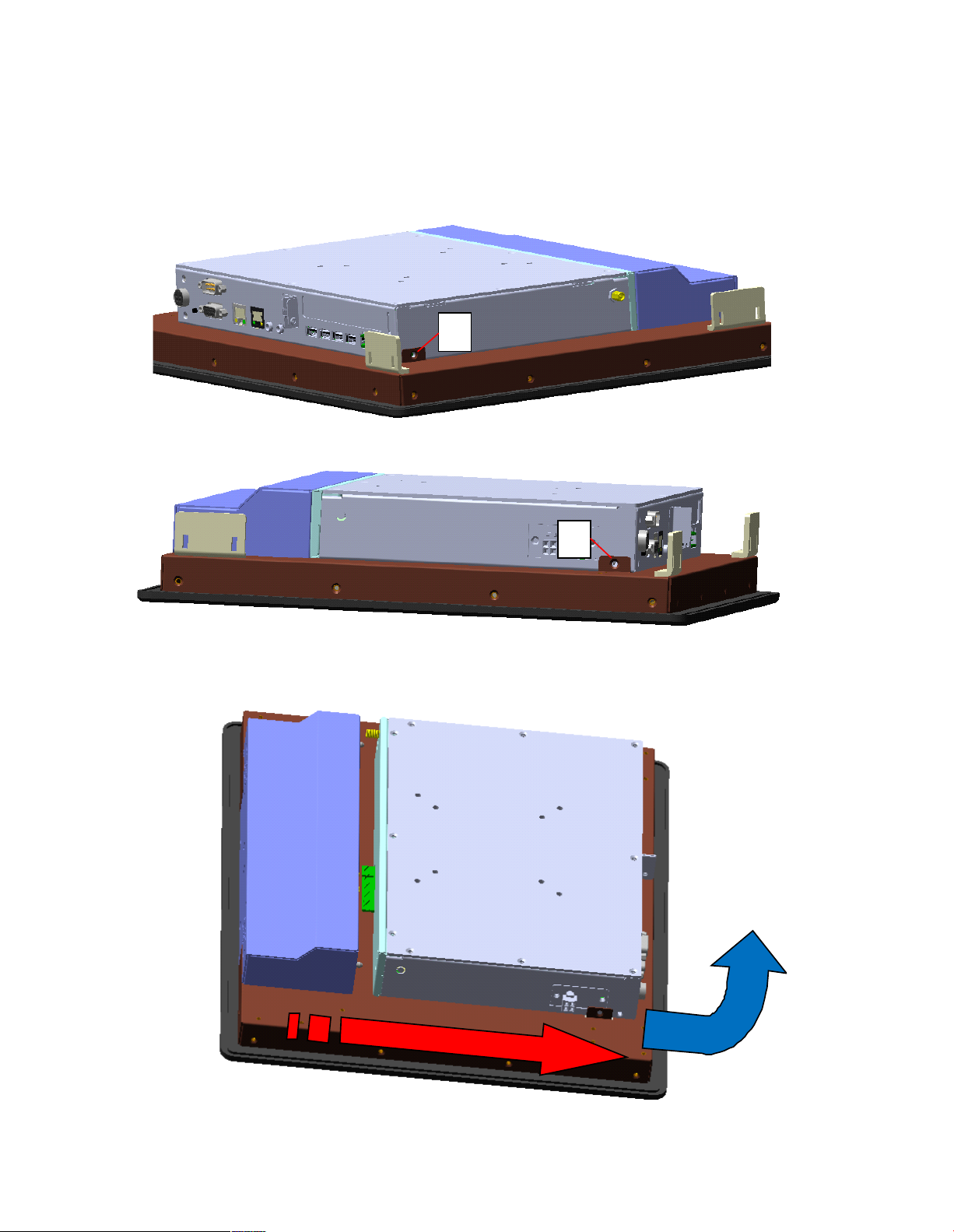
Disassembly and Assembly control box and display module
Disassembly
1. Unlock and remove screws from point A and B
A
B
2. To slide the control box to the bottom and pull to up to remove the control box.
Page 13

2. To push the control box to the top..
3. To lock point A and B screws.
A
B
 Loading...