

Page 1

User Manual
FES8914: Fanless Embedded Controller, 4-slot system with
Socket M Intel Core 2 Duo Processor
FES 8914
Fanless Embedded Controller
661 Brea Canyon Rd., Suite 3
Walnut, CA 91789
tel: 909.598.7388, fax: 909.598.0218
© Copyright 2009 Acnodes, Inc.
All rights reserved. Product description and product specifications
are subject to change without notice. For latest product information,
please visit Acnodes’ web site at www.acnodes.com.
Page 2

FES 8914
Fanless Embedded Controller
Disclaimers
This manual has been carefully checked and believed to contain accurate information.
Acnodes Corporation assumes no responsibility for any infringements of patents or any
third party’s rights, and any liability arising from such use.
Acnodes does not warrant or assume any legal liability or responsibility for the accuracy ,
completeness or usefulness of any information in this document. Acnodes does not make
any commitment to update the information in this manual.
Acnodes reserves the right to change or revise this document and/or product at any time
without notice.
No part of this document may be reproduced, stored in a retrieval system, or transmitted,
in any form or by any means, electronic, mechanical, photocopying, recording, or otherwise, without the prior written permission of ACNODES CO., Lt d.
Copyright 2009 Acnodes
Corporation All Rights Reserved
December 2009, Version A2
Printed in Taiwan
661 Brea Canyon Rd., Suite 3
Walnut, CA 91789
tel: 909.598.7388, fax: 909.598.0218
© Copyright 2005 Acnodes, Inc.
All rights reserved. Product description and product specifications
are subject to change without notice. For latest product information,
please visit Acnodes’ web site at www.acnodes.com.
Page 3

FES 8914
Fanless Embedded Controller
Safety Precautions
1. The FES 8914 does not come equipped with an operating system. An operating system must
be loaded first before installing any software into the computer .
2. Be sure to ground yourself to prevent static charge when installing the internal components.
Use a grounding wrist strap and place all electronic components in any static- shielded devices.
Most electronic components are sensitive to static electrical charge.
3. Disconnect the power cord from the FES 8914 before any installation. Be sure both the system and external devices are turned OFF . A sudden surge of power could ruin sensitive components that the FES 8914 must be properly grounded.
4. The brightness of the flat panel display will be getting weaker as a result of frequent usage.
However, the operating period varies depending on the application environment.
5. Turn OFF the system power before cleaning. Clean the system using a cloth only. Do not spray
any liquid cleaner directly onto the screen. The FES 8914 may come with or w/o a touch screen.
Although the touch screen is chemical resistant, it is recommended that you spray the liquid
cleaner on a cloth first before wiping the screen. In case your system comes without the touch
screen, you must follow the same procedure and not spray any cleaner on the flat panel directly .
6. A void using sharp objects to operate the touch screen. Scratches on the touch screen may
cause malfunction or internal failure to the touch screen.
7. The flat panel display is not susceptible to shock or vibration. When assembling the FES
8914, make sure it is securely installed.
8. Do not open the system's back cover. If opening the cover for maintenance is a must, only a
trained technician is allowed to do so. Integrated circuits on computer boards are sensitive to
static electricity . To avoid damaging chips from electrost atic discharge, observe the following
precautions:
Before handling a board or integrated circuit, touch an unpainted portion of the system unit
chassis for a few seconds. This will help to discharge any static electricity on your body .When
handling boards and components, wear a wrist- grounding strap, available from most electronic
component stores.
661 Brea Canyon Rd., Suite 3
Walnut, CA 91789
tel: 909.598.7388, fax: 909.598.0218
© Copyright 2009 Acnodes, Inc.
All rights reserved. Product description and product specifications
are subject to change without notice. For latest product information,
please visit Acnodes’ web site at www.acnodes.com.
Page 4
FES 8914
Fanless Embedded Controller
661 Brea Canyon Rd., Suite 3
Walnut, CA 91789
tel: 909.598.7388, fax: 909.598.0218
© Copyright 2005 Acnodes, Inc.
All rights reserved. Product description and product specifications
are subject to change without notice. For latest product information,
please visit Acnodes’ web site at www.acnodes.com.
Page 5

FES 8914
Fanless Embedded Controller
661 Brea Canyon Rd., Suite 3
Walnut, CA 91789
tel: 909.598.7388, fax: 909.598.0218
© Copyright 2009 Acnodes, Inc.
All rights reserved. Product description and product specifications
are subject to change without notice. For latest product information,
please visit Acnodes’ web site at www.acnodes.com.
Page 6

FES 8914
Fanless Embedded Controller
661 Brea Canyon Rd., Suite 3
Walnut, CA 91789
tel: 909.598.7388, fax: 909.598.0218
© Copyright 2005 Acnodes, Inc.
All rights reserved. Product description and product specifications
are subject to change without notice. For latest product information,
please visit Acnodes’ web site at www.acnodes.com.
Page 7

FES 8914
Fanless Embedded Controller
T able of Contents
Disclaimers ...........................................................................ii
Safety Precautions............................................................... iii
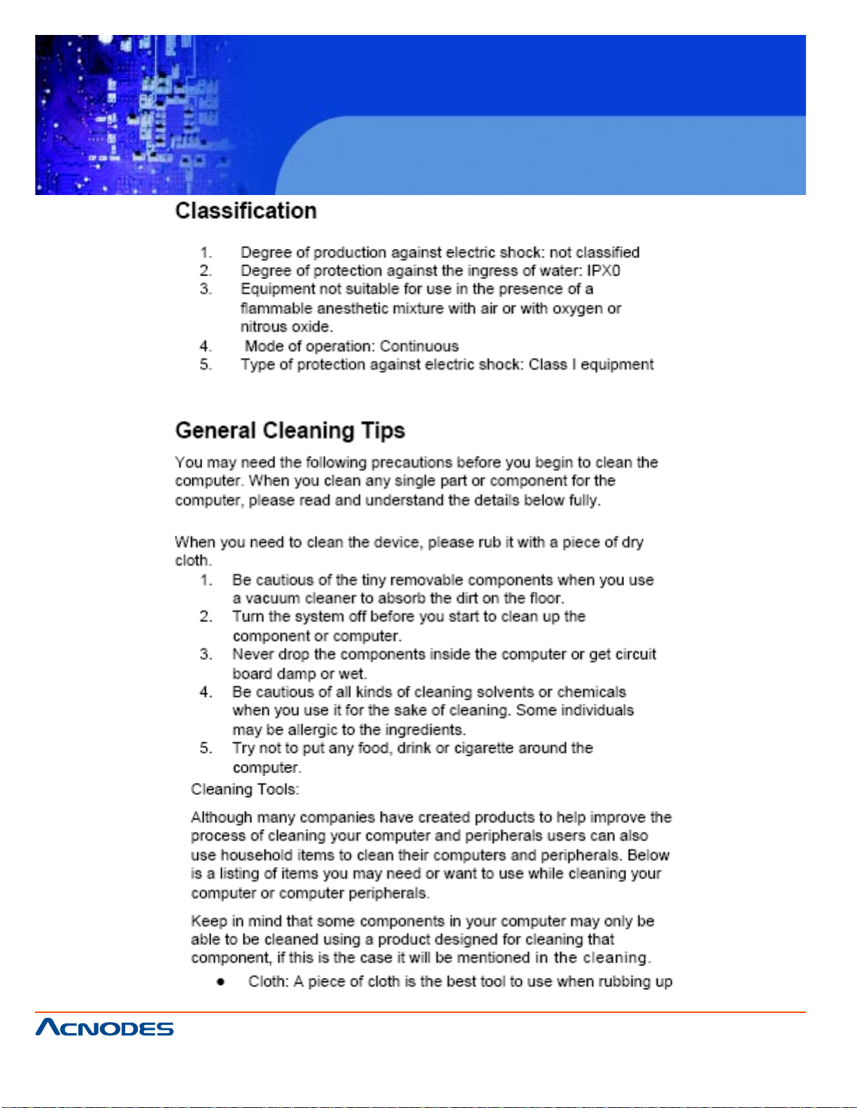
Classification.........................................................................iv
General Cleaning Ti ps..........................................................iv
Scrap Computer Recycling...................................................vi
CHAPTER 1 INTRODUCTION ....................................... 1
1.1 General Description ........................................... 1
1.2 System Specifications.........................................2
1.2.1 Main CPU Board ......................................................... 2
1.2.2 I/O System ................................................................... 2
1.2.3 System Specification .................................................. 3
1.3 Dimensions ......................................................... 4
1.4 I/O Outlets............................................................. 5
1.5 Jumper Settings .................................................. 6
1.6 Packing List ........................................................ 8
CHAPTER 2 HARDWARE INSTALLATION .................. 9
2.1 Installing the Processor ......................................... 9
2.2 Installing the Memory Module............................... 13
2.3 Installing the Hard Disk Drive................................ 15
2.4 Installing the PCI Card(when Backplane HAB104 installed)
.................................................................................. 17
CHAPTER 3 DRIVER INSTALLATION ..................... 19
3.1 Entering Setup..........................................................19
3.2 Control Keys.............................................................20
3.3 Getting Help..............................................................20
661 Brea Canyon Rd., Suite 3
Walnut, CA 91789
tel: 909.598.7388, fax: 909.598.0218
© Copyright 2009 Acnodes, Inc.
All rights reserved. Product description and product specifications
are subject to change without notice. For latest product information,
please visit Acnodes’ web site at www.acnodes.com.
Page 8

FES 8914
Fanless Embedded Controller
3.4 The Main Menu..............................................................21
3.5 Standard CMOS Setup Menu.......................................22
3.6 Advanced BIOS Features.............................................25
3.7 Advanced Chipset Features.........................................31
3.8 Integrated Peripherals...................................................33
3.9 Power Management Setup............................................39
3.10 PnP/PCI Configuration Setup........................................43
3.11 PC Health St atus............................................................45
3.12 Frequency/V oltage Control.............................................46
3.13 Load Optimized Defaults................................................47
3.14 Set Supervisor/ User Password.....................................48
3.15 Save & Exit Setup...........................................................49
3.16 Exit Without Saving.........................................................50
661 Brea Canyon Rd., Suite 3
Walnut, CA 91789
tel: 909.598.7388, fax: 909.598.0218
© Copyright 2005 Acnodes, Inc.
All rights reserved. Product description and product specifications
are subject to change without notice. For latest product information,
please visit Acnodes’ web site at www.acnodes.com.
Page 9

FES 8914
Fanless Embedded Controller
CHAPTER 1 INTRODUCTION
This chapter contains general information and detailed specifications of the FES 8914 Chapter 1
includes the following sections:
General Description
System Specification
Dimensions
I/O Outlets
Package List
1.1 General Description
The FES8914 is an embedded system that can support Socket M for Intel® CoreTM 2 Duo/
CoreTM Duo or Celeron® M processors. The FES8914 supports Windows® 2000, Windows® XP,
and ® Windows XP embedded, suitable for the most endurable operation.
Reliable and Stable Design
The FES8914 adopts an anti-vibration hard-drive bay , which makes it especially suitable for vibration environments, best for industrial automation, digital signage and gaming application.
Embedded O.S. Supported
The FES8914 not only supports Windows® 2000, Windows® XP, but also supports embedded OS,
such as Windows® XP embedded. For storage device, the FES8914 supports one 2.5" HDD driver
bay and one onboard CompactFlash™ socket.
661 Brea Canyon Rd., Suite 3
Walnut, CA 91789
tel: 909.598.7388, fax: 909.598.0218
© Copyright 2009 Acnodes, Inc.
All rights reserved. Product description and product specifications
are subject to change without notice. For latest product information,
please visit Acnodes’ web site at www.acnodes.com.
Page 10

1.2 Specifications
1.2.1 Main CPI board
CPU:
Socket type Intel Core 2 Duo/ Core Duo or Celeron M processors
System Chipset: Intel 945GME chipset
BIOS:
Phoenix-Award BIOS, 4mbit with RPL/PXE LAN Boot ROM, SmartView and Customer CMOS
Backup
System Memory:
T wo 200-pin DDR2 533/667 MHz SODIMM sockets, with maximum up to 4GB
Features:
-Fanless Operation
-Compact & Front IO design
-Supports four PCI or four PCI & PCIe expansion slots
-DC to DC power supply support 10V to 30V
FES 8914
Fanless Embedded Controller
1.2.2 I/O System
Standard I/O Interface- Front:
-A TX power on/off switch
-10VDC to 30VDC with phoenix power plug or External 150W AC Adapter
-Two USB 2.0 port s
-HDD access/power LEDs
-One RS-232(COM2)
-One RD-232/422/485(COM1)
-One VGA connector
-T wo G .E. LAN port s
661 Brea Canyon Rd., Suite 3
Walnut, CA 91789
tel: 909.598.7388, fax: 909.598.0218
© Copyright 2005 Acnodes, Inc.
All rights reserved. Product description and product specifications
are subject to change without notice. For latest product information,
please visit Acnodes’ web site at www.acnodes.com.
Page 11
FES 8914
Fanless Embedded Controller
Optional I/O through bracket (Customer Selectable)
-Two COM port
-Four USB
-One DVI-D
Expansion Slot:
-Four PCI slots when backplane HAB104 installed
-Two PCI & One PCIe x 1 & One PCIe x 16 slot s when backplane HAB105 installed
1.2.3 System Specification
Drive Capacity:
-Supports one 2.5” HDD driver bay; one onboard CompactFlash socket
Power Input:
-10VDC to 30VDC with phoenix power plug
-External 150W AC Adapter
Power Input: 90V AC to 264VAC, 7.89A 47/63Hz
Power Output: 19VDC
Operating temperature:
-Ambient with air flow: 0°C to 45°C
Storage Temperature:
-20°C to 80°C
Relative humidity: 10% to 90%, non-condensing
Dimensions: 7.2” (W) x 9.8” (D) x 7.3” (H)
661 Brea Canyon Rd., Suite 3
Walnut, CA 91789
tel: 909.598.7388, fax: 909.598.0218
© Copyright 2009 Acnodes, Inc.
All rights reserved. Product description and product specifications
are subject to change without notice. For latest product information,
please visit Acnodes’ web site at www.acnodes.com.
Page 12
FES 8914
Fanless Embedded Controller
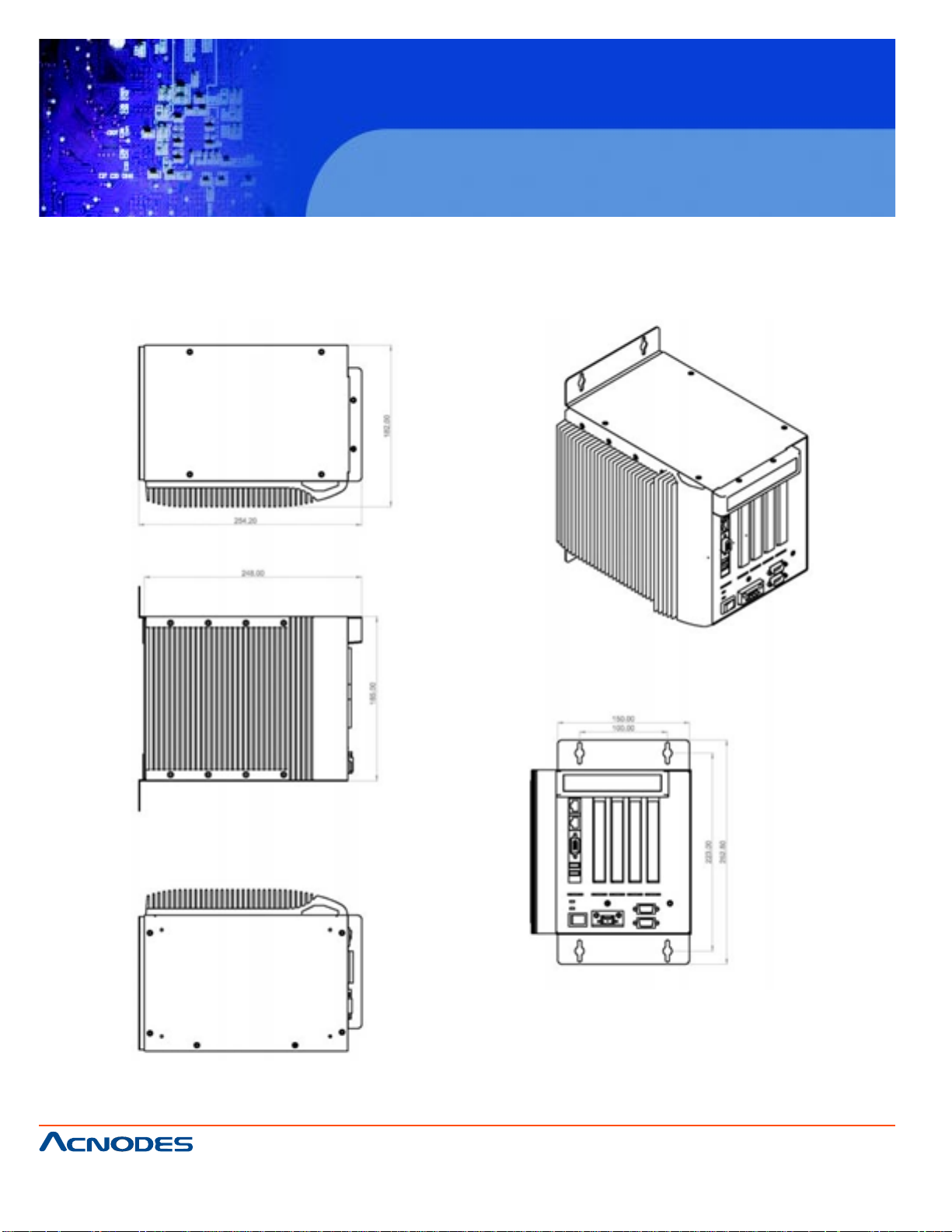
1.3 Dimensions
The following diagrams show the dimensions and outlines of FES8914.
661 Brea Canyon Rd., Suite 3
Walnut, CA 91789
tel: 909.598.7388, fax: 909.598.0218
© Copyright 2005 Acnodes, Inc.
All rights reserved. Product description and product specifications
are subject to change without notice. For latest product information,
please visit Acnodes’ web site at www.acnodes.com.
Page 13
FES 8914
Fanless Embedded Controller
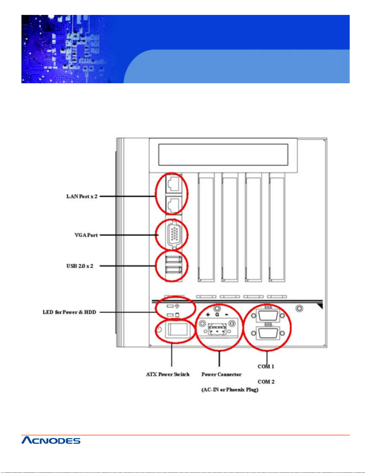
1.4 I/O Outlets
The following figure show you I/O outlets on front and rear panels of the FES8914.
661 Brea Canyon Rd., Suite 3
Walnut, CA 91789
tel: 909.598.7388, fax: 909.598.0218
© Copyright 2009 Acnodes, Inc.
All rights reserved. Product description and product specifications
are subject to change without notice. For latest product information,
please visit Acnodes’ web site at www.acnodes.com.
Page 14
FES 8914
Fanless Embedded Controller
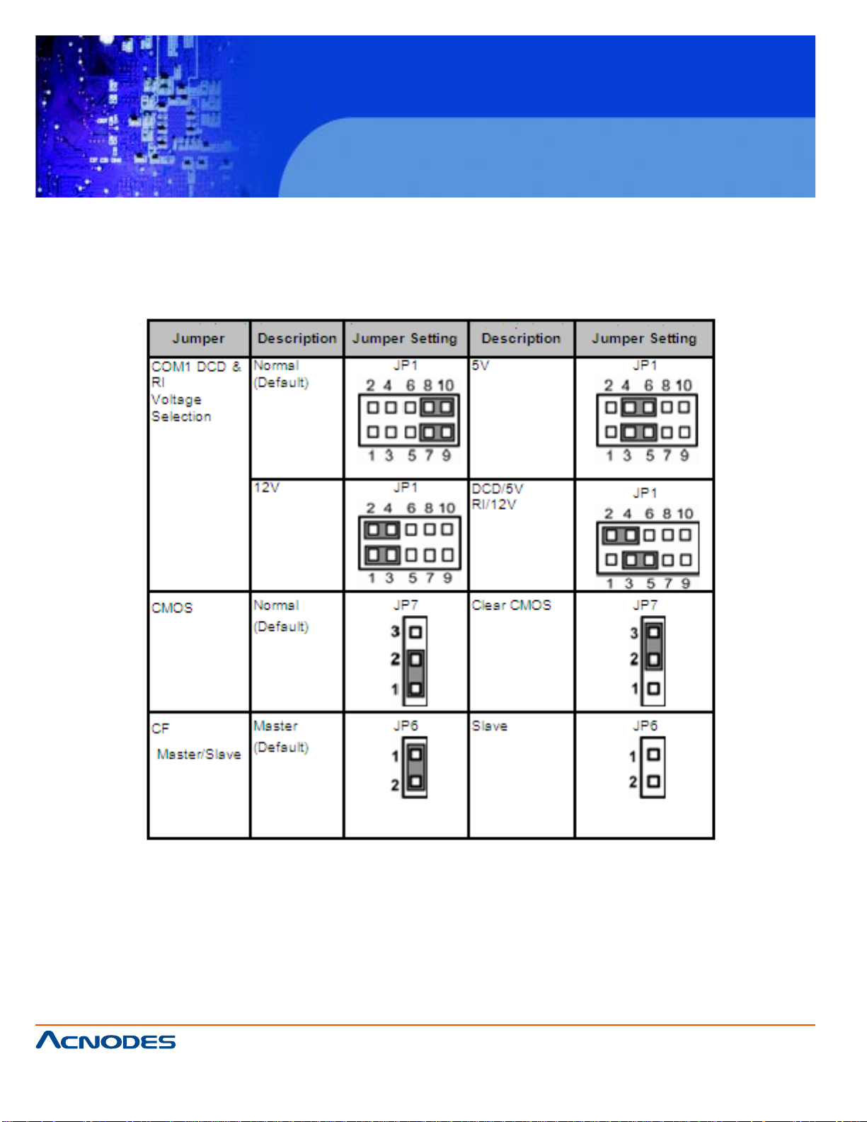
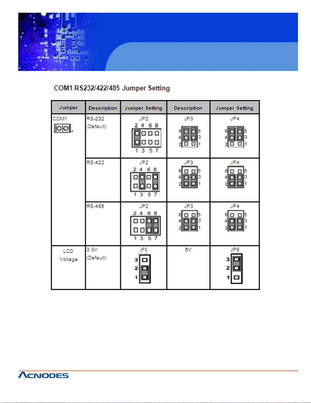
1.5 Jumper Settings
The FES8914 has a number of jumpers inside the chassis that allow you to configure your system
to suit your application. The table below lists the functions of the various jumpers.
661 Brea Canyon Rd., Suite 3
Walnut, CA 91789
tel: 909.598.7388, fax: 909.598.0218
© Copyright 2005 Acnodes, Inc.
All rights reserved. Product description and product specifications
are subject to change without notice. For latest product information,
please visit Acnodes’ web site at www.acnodes.com.
Page 15
FES 8914
Fanless Embedded Controller
661 Brea Canyon Rd., Suite 3
Walnut, CA 91789
tel: 909.598.7388, fax: 909.598.0218
© Copyright 2009 Acnodes, Inc.
All rights reserved. Product description and product specifications
are subject to change without notice. For latest product information,
please visit Acnodes’ web site at www.acnodes.com.
Page 16

FES 8914
Fanless Embedded Controller
1.6 Packing List
The package bundled with your FES8914 should contain the following items:
-FPC8914 Unit x 1
-19V 150W Adapter (for FPC8914 AC Version)
-Driver CD
-Quick Manual
-Wall Mount Bracket x 2
-HD Screw x 4
If you can not find this package or any items are missing, please contact Acnodes Corp. distributors
immediately.
661 Brea Canyon Rd., Suite 3
Walnut, CA 91789
tel: 909.598.7388, fax: 909.598.0218
© Copyright 2005 Acnodes, Inc.
All rights reserved. Product description and product specifications
are subject to change without notice. For latest product information,
please visit Acnodes’ web site at www.acnodes.com.
Page 17

FES 8914
Fanless Embedded Controller
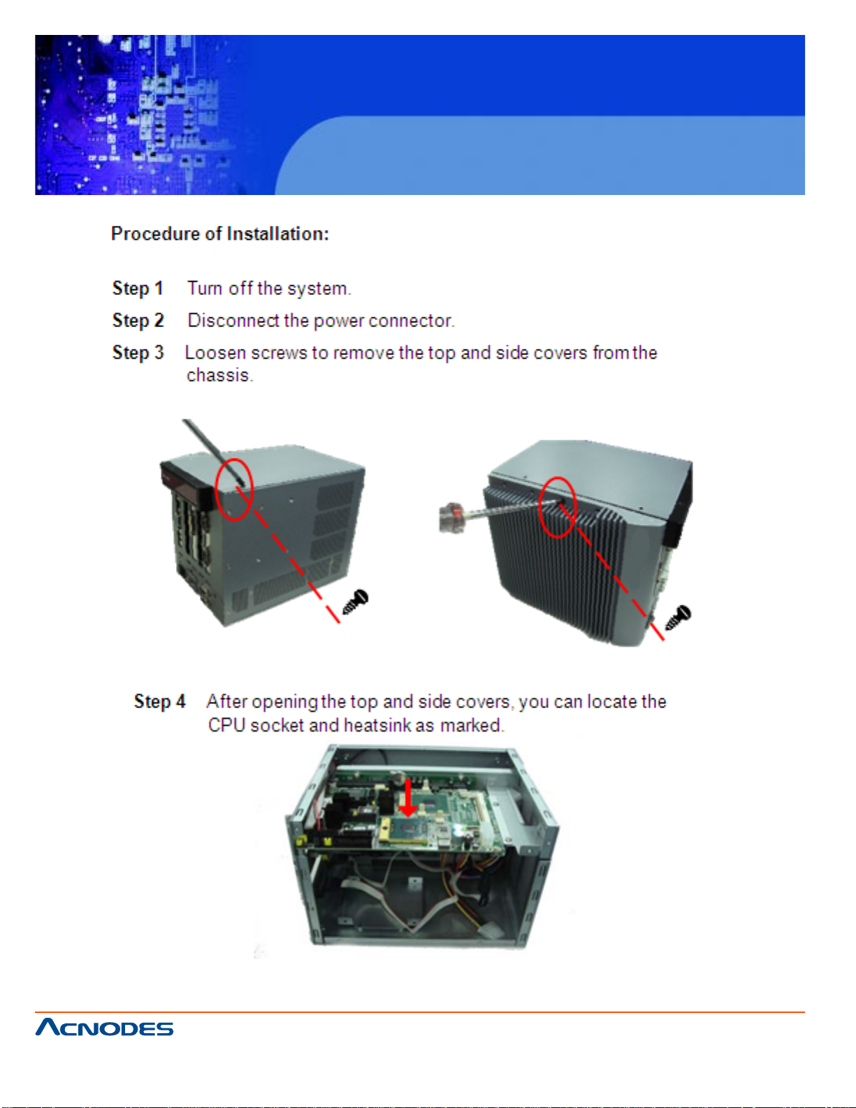
CHAPTER 2 HARDWARE INST ALLATION
The FES8914 are convenient for your various hardware configurations, such as CPU (Central
Processing Unit), Memory Module, HDD (Hard Disk Drive) and PCIe card. The chapter 2 will
show you how to install the hardware. It includes:
2.1 HDD Installation
The Intel® Pentium® M Processor is available as a boxed processor for laptop computers in
the micro-FCPGA form factor. Intel recommends
the processor should be installed by a computer professional since this electronic device may
cause serious damage to the installer, system and processor if inst alled improperly.
Important Notes Before attempting to install a new processor, carefully review the documentation that came with your system and make sure that you will not be voiding your warranty by
opening the computer or replacing your processor.
Instructions:
1.Make sure that your system can accommodate the Intel® Pentium® M Processor that you
want to install. Check for motherboard, BIOS, and thermal compatibility by using the
manufacturer's documentation for the laptop computer , or by contacting the vendor if necessary.
This processor should only be installed in systems supporting the Intel® Pentium® M Processor.
Important Notes Do not use an Intel® Pentium® M Processor in a desktop system and do not
use a desktop processor in an Intel® Pentium® M Processor notebook. Since these processors have different electrical specifications, damage to the processor and system can occur .
2.Obtain access to your processor socket as described in the documentation for your system.
3.If the cooling solution prevents you from accessing the processor socket, you may need to
remove it. Instructions on how to remove your cooling solution should be provided in the documentation that came with the system.
4.To un-install the current processor, use a screwdriver to disengage (open) the socket actuator, as shown in Figure 1 below. (The most commonly used sockets are Molex* or FoxConn*
sockets, so they are used in the illustrations below .) The socket actuator should open af ter only
a half turn or so, and you should then be able to remove the processor with your fingers.
661 Brea Canyon Rd., Suite 3
Walnut, CA 91789
tel: 909.598.7388, fax: 909.598.0218
© Copyright 2009 Acnodes, Inc.
All rights reserved. Product description and product specifications
are subject to change without notice. For latest product information,
please visit Acnodes’ web site at www.acnodes.com.
Page 18
FES 8914
Fanless Embedded Controller
661 Brea Canyon Rd., Suite 3
Walnut, CA 91789
tel: 909.598.7388, fax: 909.598.0218
© Copyright 2005 Acnodes, Inc.
All rights reserved. Product description and product specifications
are subject to change without notice. For latest product information,
please visit Acnodes’ web site at www.acnodes.com.
Page 19

FES 8914
Fanless Embedded Controller
661 Brea Canyon Rd., Suite 3
Walnut, CA 91789
tel: 909.598.7388, fax: 909.598.0218
© Copyright 2009 Acnodes, Inc.
All rights reserved. Product description and product specifications
are subject to change without notice. For latest product information,
please visit Acnodes’ web site at www.acnodes.com.
Page 20

FES 8914
Fanless Embedded Controller
661 Brea Canyon Rd., Suite 3
Walnut, CA 91789
tel: 909.598.7388, fax: 909.598.0218
© Copyright 2005 Acnodes, Inc.
All rights reserved. Product description and product specifications
are subject to change without notice. For latest product information,
please visit Acnodes’ web site at www.acnodes.com.
Page 21

2.2 Installing the Memory Module
FES 8914
Fanless Embedded Controller
661 Brea Canyon Rd., Suite 3
Walnut, CA 91789
tel: 909.598.7388, fax: 909.598.0218
© Copyright 2009 Acnodes, Inc.
All rights reserved. Product description and product specifications
are subject to change without notice. For latest product information,
please visit Acnodes’ web site at www.acnodes.com.
Page 22

FES 8914
Fanless Embedded Controller
661 Brea Canyon Rd., Suite 3
Walnut, CA 91789
tel: 909.598.7388, fax: 909.598.0218
© Copyright 2005 Acnodes, Inc.
All rights reserved. Product description and product specifications
are subject to change without notice. For latest product information,
please visit Acnodes’ web site at www.acnodes.com.
Page 23

FES 8914
Fanless Embedded Controller
2. 3 Installing the Hard Disk Drive
The FES8914 offers a convenient drive bay module for users to install HDD. The system offers users
one 2.5" Hard Disk Drive for installation. Please follow the steps:
661 Brea Canyon Rd., Suite 3
Walnut, CA 91789
tel: 909.598.7388, fax: 909.598.0218
© Copyright 2009 Acnodes, Inc.
All rights reserved. Product description and product specifications
are subject to change without notice. For latest product information,
please visit Acnodes’ web site at www.acnodes.com.
Page 24

FES 8914
Fanless Embedded Controller
661 Brea Canyon Rd., Suite 3
Walnut, CA 91789
tel: 909.598.7388, fax: 909.598.0218
© Copyright 2005 Acnodes, Inc.
All rights reserved. Product description and product specifications
are subject to change without notice. For latest product information,
please visit Acnodes’ web site at www.acnodes.com.
Page 25

FES 8914
Fanless Embedded Controller
2.4 Installing the PCI Card (when Backplane HAB104 installed)
661 Brea Canyon Rd., Suite 3
Walnut, CA 91789
tel: 909.598.7388, fax: 909.598.0218
© Copyright 2009 Acnodes, Inc.
All rights reserved. Product description and product specifications
are subject to change without notice. For latest product information,
please visit Acnodes’ web site at www.acnodes.com.
Page 26

FES 8914
Fanless Embedded Controller
661 Brea Canyon Rd., Suite 3
Walnut, CA 91789
tel: 909.598.7388, fax: 909.598.0218
© Copyright 2005 Acnodes, Inc.
All rights reserved. Product description and product specifications
are subject to change without notice. For latest product information,
please visit Acnodes’ web site at www.acnodes.com.
Page 27

FES 8914
Fanless Embedded Controller
CHAPTER 3 PHOENIX-AWARD BIOS UTILITY
The Phoenix-Award BIOS provides users with a built-in Setup program to modify basic system
configuration. All configured parameters are stored in a battery-backed-up RAM (CMOS RAM) to
save the Setup information whenever the power is turned off.
3.1 Entering Setup
There are two ways to enter the Setup program. You may either turn ON the computer and
press <Del> immediately , or press the <Del> and/or <Ctrl>, <Alt>, and <Esc> keys simult aneously when the following message appears at the bottom of the screen during POST
(Power on Self Test).
TO ENTER SETUP PRESS DEL KEY
If the message disappears before you respond and you still want to enter Setup, please
restart the system to try it again. T urning the system power OFF and ON, pressing the "RESET" button on the system case or simultaneously pressing <Ctrl>, <Alt>, and <Del> keys
can restart the system. If you do not press keys at the right time and the system doesn't boot,
an error message will pop out to prompt you the following information:
PRESS <F1> TO CONTINUE, <CTRL-ALT-ESC> OR <DEL> TO ENTER SETUP
661 Brea Canyon Rd., Suite 3
Walnut, CA 91789
tel: 909.598.7388, fax: 909.598.0218
© Copyright 2009 Acnodes, Inc.
All rights reserved. Product description and product specifications
are subject to change without notice. For latest product information,
please visit Acnodes’ web site at www.acnodes.com.
Page 28

FES 8914
Fanless Embedded Controller
661 Brea Canyon Rd., Suite 3
Walnut, CA 91789
tel: 909.598.7388, fax: 909.598.0218
© Copyright 2005 Acnodes, Inc.
All rights reserved. Product description and product specifications
are subject to change without notice. For latest product information,
please visit Acnodes’ web site at www.acnodes.com.
Page 29

FES 8914
Fanless Embedded Controller
661 Brea Canyon Rd., Suite 3
Walnut, CA 91789
tel: 909.598.7388, fax: 909.598.0218
© Copyright 2009 Acnodes, Inc.
All rights reserved. Product description and product specifications
are subject to change without notice. For latest product information,
please visit Acnodes’ web site at www.acnodes.com.
Page 30

FES 8914
Fanless Embedded Controller
661 Brea Canyon Rd., Suite 3
Walnut, CA 91789
tel: 909.598.7388, fax: 909.598.0218
© Copyright 2005 Acnodes, Inc.
All rights reserved. Product description and product specifications
are subject to change without notice. For latest product information,
please visit Acnodes’ web site at www.acnodes.com.
Page 31

FES 8914
Fanless Embedded Controller
661 Brea Canyon Rd., Suite 3
Walnut, CA 91789
tel: 909.598.7388, fax: 909.598.0218
© Copyright 2009 Acnodes, Inc.
All rights reserved. Product description and product specifications
are subject to change without notice. For latest product information,
please visit Acnodes’ web site at www.acnodes.com.
Page 32

FES 8914
Fanless Embedded Controller
661 Brea Canyon Rd., Suite 3
Walnut, CA 91789
tel: 909.598.7388, fax: 909.598.0218
© Copyright 2005 Acnodes, Inc.
All rights reserved. Product description and product specifications
are subject to change without notice. For latest product information,
please visit Acnodes’ web site at www.acnodes.com.
Page 33

FES 8914
Fanless Embedded Controller
661 Brea Canyon Rd., Suite 3
Walnut, CA 91789
tel: 909.598.7388, fax: 909.598.0218
© Copyright 2009 Acnodes, Inc.
All rights reserved. Product description and product specifications
are subject to change without notice. For latest product information,
please visit Acnodes’ web site at www.acnodes.com.
Page 34

FES 8914
Fanless Embedded Controller
661 Brea Canyon Rd., Suite 3
Walnut, CA 91789
tel: 909.598.7388, fax: 909.598.0218
© Copyright 2005 Acnodes, Inc.
All rights reserved. Product description and product specifications
are subject to change without notice. For latest product information,
please visit Acnodes’ web site at www.acnodes.com.
Page 35

FES 8914
Fanless Embedded Controller
661 Brea Canyon Rd., Suite 3
Walnut, CA 91789
tel: 909.598.7388, fax: 909.598.0218
© Copyright 2009 Acnodes, Inc.
All rights reserved. Product description and product specifications
are subject to change without notice. For latest product information,
please visit Acnodes’ web site at www.acnodes.com.
Page 36

FES 8914
Fanless Embedded Controller
661 Brea Canyon Rd., Suite 3
Walnut, CA 91789
tel: 909.598.7388, fax: 909.598.0218
© Copyright 2005 Acnodes, Inc.
All rights reserved. Product description and product specifications
are subject to change without notice. For latest product information,
please visit Acnodes’ web site at www.acnodes.com.
Page 37

FES 8914
Fanless Embedded Controller
661 Brea Canyon Rd., Suite 3
Walnut, CA 91789
tel: 909.598.7388, fax: 909.598.0218
© Copyright 2009 Acnodes, Inc.
All rights reserved. Product description and product specifications
are subject to change without notice. For latest product information,
please visit Acnodes’ web site at www.acnodes.com.
Page 38

FES 8914
Fanless Embedded Controller
661 Brea Canyon Rd., Suite 3
Walnut, CA 91789
tel: 909.598.7388, fax: 909.598.0218
© Copyright 2005 Acnodes, Inc.
All rights reserved. Product description and product specifications
are subject to change without notice. For latest product information,
please visit Acnodes’ web site at www.acnodes.com.
Page 39

FES 8914
Fanless Embedded Controller
661 Brea Canyon Rd., Suite 3
Walnut, CA 91789
tel: 909.598.7388, fax: 909.598.0218
© Copyright 2009 Acnodes, Inc.
All rights reserved. Product description and product specifications
are subject to change without notice. For latest product information,
please visit Acnodes’ web site at www.acnodes.com.
Page 40

FES 8914
Fanless Embedded Controller
661 Brea Canyon Rd., Suite 3
Walnut, CA 91789
tel: 909.598.7388, fax: 909.598.0218
© Copyright 2005 Acnodes, Inc.
All rights reserved. Product description and product specifications
are subject to change without notice. For latest product information,
please visit Acnodes’ web site at www.acnodes.com.
Page 41

FES 8914
Fanless Embedded Controller
661 Brea Canyon Rd., Suite 3
Walnut, CA 91789
tel: 909.598.7388, fax: 909.598.0218
© Copyright 2009 Acnodes, Inc.
All rights reserved. Product description and product specifications
are subject to change without notice. For latest product information,
please visit Acnodes’ web site at www.acnodes.com.
Page 42

FES 8914
Fanless Embedded Controller
661 Brea Canyon Rd., Suite 3
Walnut, CA 91789
tel: 909.598.7388, fax: 909.598.0218
© Copyright 2005 Acnodes, Inc.
All rights reserved. Product description and product specifications
are subject to change without notice. For latest product information,
please visit Acnodes’ web site at www.acnodes.com.
Page 43

FES 8914
Fanless Embedded Controller
661 Brea Canyon Rd., Suite 3
Walnut, CA 91789
tel: 909.598.7388, fax: 909.598.0218
© Copyright 2009 Acnodes, Inc.
All rights reserved. Product description and product specifications
are subject to change without notice. For latest product information,
please visit Acnodes’ web site at www.acnodes.com.
Page 44

FES 8914
Fanless Embedded Controller
661 Brea Canyon Rd., Suite 3
Walnut, CA 91789
tel: 909.598.7388, fax: 909.598.0218
© Copyright 2005 Acnodes, Inc.
All rights reserved. Product description and product specifications
are subject to change without notice. For latest product information,
please visit Acnodes’ web site at www.acnodes.com.
Page 45

FES 8914
Fanless Embedded Controller
661 Brea Canyon Rd., Suite 3
Walnut, CA 91789
tel: 909.598.7388, fax: 909.598.0218
© Copyright 2009 Acnodes, Inc.
All rights reserved. Product description and product specifications
are subject to change without notice. For latest product information,
please visit Acnodes’ web site at www.acnodes.com.
Page 46

FES 8914
Fanless Embedded Controller
661 Brea Canyon Rd., Suite 3
Walnut, CA 91789
tel: 909.598.7388, fax: 909.598.0218
© Copyright 2005 Acnodes, Inc.
All rights reserved. Product description and product specifications
are subject to change without notice. For latest product information,
please visit Acnodes’ web site at www.acnodes.com.
Page 47

FES 8914
Fanless Embedded Controller
661 Brea Canyon Rd., Suite 3
Walnut, CA 91789
tel: 909.598.7388, fax: 909.598.0218
© Copyright 2009 Acnodes, Inc.
All rights reserved. Product description and product specifications
are subject to change without notice. For latest product information,
please visit Acnodes’ web site at www.acnodes.com.
Page 48

FES 8914
Fanless Embedded Controller
661 Brea Canyon Rd., Suite 3
Walnut, CA 91789
tel: 909.598.7388, fax: 909.598.0218
© Copyright 2005 Acnodes, Inc.
All rights reserved. Product description and product specifications
are subject to change without notice. For latest product information,
please visit Acnodes’ web site at www.acnodes.com.
Page 49

FES 8914
Fanless Embedded Controller
661 Brea Canyon Rd., Suite 3
Walnut, CA 91789
tel: 909.598.7388, fax: 909.598.0218
© Copyright 2009 Acnodes, Inc.
All rights reserved. Product description and product specifications
are subject to change without notice. For latest product information,
please visit Acnodes’ web site at www.acnodes.com.
Page 50

FES 8914
Fanless Embedded Controller
661 Brea Canyon Rd., Suite 3
Walnut, CA 91789
tel: 909.598.7388, fax: 909.598.0218
© Copyright 2005 Acnodes, Inc.
All rights reserved. Product description and product specifications
are subject to change without notice. For latest product information,
please visit Acnodes’ web site at www.acnodes.com.
Page 51

FES 8914
Fanless Embedded Controller
661 Brea Canyon Rd., Suite 3
Walnut, CA 91789
tel: 909.598.7388, fax: 909.598.0218
© Copyright 2009 Acnodes, Inc.
All rights reserved. Product description and product specifications
are subject to change without notice. For latest product information,
please visit Acnodes’ web site at www.acnodes.com.
Page 52

FES 8914
Fanless Embedded Controller
661 Brea Canyon Rd., Suite 3
Walnut, CA 91789
tel: 909.598.7388, fax: 909.598.0218
© Copyright 2005 Acnodes, Inc.
All rights reserved. Product description and product specifications
are subject to change without notice. For latest product information,
please visit Acnodes’ web site at www.acnodes.com.
Page 53

FES 8914
Fanless Embedded Controller
661 Brea Canyon Rd., Suite 3
Walnut, CA 91789
tel: 909.598.7388, fax: 909.598.0218
© Copyright 2009 Acnodes, Inc.
All rights reserved. Product description and product specifications
are subject to change without notice. For latest product information,
please visit Acnodes’ web site at www.acnodes.com.
Page 54

FES 8914
Fanless Embedded Controller
661 Brea Canyon Rd., Suite 3
Walnut, CA 91789
tel: 909.598.7388, fax: 909.598.0218
© Copyright 2005 Acnodes, Inc.
All rights reserved. Product description and product specifications
are subject to change without notice. For latest product information,
please visit Acnodes’ web site at www.acnodes.com.
Page 55

FES 8914
Fanless Embedded Controller
661 Brea Canyon Rd., Suite 3
Walnut, CA 91789
tel: 909.598.7388, fax: 909.598.0218
© Copyright 2009 Acnodes, Inc.
All rights reserved. Product description and product specifications
are subject to change without notice. For latest product information,
please visit Acnodes’ web site at www.acnodes.com.
Page 56

FES 8914
Fanless Embedded Controller
661 Brea Canyon Rd., Suite 3
Walnut, CA 91789
tel: 909.598.7388, fax: 909.598.0218
© Copyright 2005 Acnodes, Inc.
All rights reserved. Product description and product specifications
are subject to change without notice. For latest product information,
please visit Acnodes’ web site at www.acnodes.com.
Page 57

FES 8914
Fanless Embedded Controller
661 Brea Canyon Rd., Suite 3
Walnut, CA 91789
tel: 909.598.7388, fax: 909.598.0218
© Copyright 2009 Acnodes, Inc.
All rights reserved. Product description and product specifications
are subject to change without notice. For latest product information,
please visit Acnodes’ web site at www.acnodes.com.
Page 58

FES 8914
Fanless Embedded Controller
661 Brea Canyon Rd., Suite 3
Walnut, CA 91789
tel: 909.598.7388, fax: 909.598.0218
© Copyright 2005 Acnodes, Inc.
All rights reserved. Product description and product specifications
are subject to change without notice. For latest product information,
please visit Acnodes’ web site at www.acnodes.com.
 Loading...