

Page 1

User Manual
FES-7510
Fanless Embedded Controller
Intel Celeron M ULV
Processor
FES7510
Fanless Embedded Controller comes with
Intel Celeron M ULV Processor
661 Brea Canyon Rd., Suite 3
Walnut, CA 91789
tel: 909.598.7388, fax: 909.598.0218, www.acnodes.com
© Copyright 2009 Acnodes, Inc.
All rights reserved. Product description and product specifications
are subject to change without notice. For latest product information,
please visit Acnodes’ web site at www.acnodes.com.
Page 2

FES7510
Fanless Embedded Controller comes with
Intel Celeron M ULV Processor
COPYRIGHT NOTICE
This operation manual is meant to assist both Embedded Computer manufacturers and end
users in installing and setting up the system. The information contained in this document is subject
to change without any notice.
This manual is copyrighted in August, 2008. Y ou may not reproduce or transmit in any form
or by any means, electronic, or mechanical, including photocopying and recording.
ACKNOWLEDGEMENTS
All trademarks and registered trademarks mentioned herein are the property of their respective owners.
CE NOTICE
This is a class A product. In a domestic environment this product may cause radio
interfernce in which case the user may be required to take adequate measures.
FCC NOTICE
This equipment has been tested and found to comply with the limits for a Class A digital
device, pursuant to part 15 of the FCC Rules. These limits are designed to provide reasonable protection against harmful interference when the equipment is operated in a
commercial environment. This equipment generates, uses, and can radiate radio frequency energy
and, if not installed and used in accordance with the instruction manual, may cause harmful interference to radio communications. Operation of this equipment in a residential area is likely
to cause harmful interference in which case the user will be required to correct the interference at his own expense.
Y ou are cautioned that any change or modifications to the equipment not expressly approve by the
party responsible for compliance could void your authority to operate such equipment.
661 Brea Canyon Rd., Suite 3
Walnut, CA 91789
tel: 909.598.7388, fax: 909.598.0218, www.acnodes.com
© Copyright 2009 Acnodes, Inc.
All rights reserved. Product description and product specifications
are subject to change without notice. For latest product information,
please visit Acnodes’ web site at www.acnodes.com.
Page 3

Contents
Chapter 1 Introduction
1.1 About This Manual............................................................................ 2
1.2 Case Illustration............................................................................ ....3
1.3 System Specification....................................................................... 4-6
1.4 Safety Precautions........................................................................... 6
Chapter 2 Hardware Configuration
2.1 Jumpers & Connector Quick Reference T able............................8
2.2 Componant Locations....................................................................9
2.3 How to Set the Jumpers.............................................................. .10-1 1
FES7510
Fanless Embedded Controller comes with
Intel Celeron M ULV Processor
2.4 FSB Clock Frequency Selection..................................................12
2.5 915 GME Core V oltage Selection...............................................13
2.6 Clear CMOS Data Selection........................................................14
2.7 ATX Power Button..........................................................................14
2.8 Keyboard or PS/2 Mouse Connector.......................................... 14
2.9 Keyboard or PS/2 Mouse Selection............................................ 15
2.10 Reset Connector ...........................................................................16
2.1 1 Keylock Connector........................................................................17
2.12 External Buzzer Connector..........................................................17
2.13 Power LED Connector .................................................................18
2.14 Hard Disk Drive LED Connector................................................19
2.15 CPU FAN Connector ................................................................. ..19
2.16 System FAN Connector ...............................................................20
2.17 Compact Flash Connector ..........................................................21
661 Brea Canyon Rd., Suite 3
Walnut, CA 91789
tel: 909.598.7388, fax: 909.598.0218, www.acnodes.com
© Copyright 2009 Acnodes, Inc.
All rights reserved. Product description and product specifications
are subject to change without notice. For latest product information,
please visit Acnodes’ web site at www.acnodes.com.
Page 4

FES7510
Fanless Embedded Controller comes with
Intel Celeron M ULV Processor
2.18 COM Port Connector ............................................................... 21
2.19 COM1/2 RI & Voltage Selection............................................. 21
2.20 VGA Connector ........................................................................ 21
2.21 Serial AT A Connector............................................................... 21
2.22 DVI Connector .......................................................................... 21
2.23 Universal Serial Bus Connector............................................. 21
2.24 Giga LAN Connector............................................................... 21
2.25 ATX Power Connector............................................................. 21
2.26 A TX/ A T Power Selection........................................................ 21
2.27 Memory Installation.................................................................. 21
2.28 Reset/ NMI Selection............................................................... 21
2.29 Sound Connector ..................................................................... 21
2.29-1 Line-In or MIC-In Selection.................................................. 21
2.30 1394 Connector ....................................................................... 21
2.31 Digital I/O Port........................................................................ .21
2.32 L VDS Connector..................................................................... .21
2.33 L VDS Panel Voltage Selection............................................. .21
2.34 Inverter Connector ........................................................................ .21
Chapter 3 Software Utilities
3.1 Introduction.................................................................................23
3.2 VGA Driver Utility .......................................................................24
3.3 Flash BIOS Update...................................................................25-26
3.4 LAN Driver Utility........................................................................27
661 Brea Canyon Rd., Suite 3
Walnut, CA 91789
tel: 909.598.7388, fax: 909.598.0218, www.acnodes.com
© Copyright 2009 Acnodes, Inc.
All rights reserved. Product description and product specifications
are subject to change without notice. For latest product information,
please visit Acnodes’ web site at www.acnodes.com.
Page 5

3.5 Sound Driver Utility....................................................................28
3.6 Intel Chipset Software Installation utility...................................29
3.7 Watchdog T imer Configuration.................................................31-32
Chapter 4 Award BIOS Setup
4.1 Introduction.................................................................................34
4.2 Entering Setup...........................................................................35
4.3 The S tandard CMOS Features................................................36-40
4.4 The Advanced BIOS Features.................................................41-42
4.5 Advanced Chipset Features....................................................43-45
4.6 Integrated Peripherals..............................................................46-49
FES7510
Fanless Embedded Controller comes with
Intel Celeron M ULV Processor
4.7 Power Management Setup......................................................50
4.8 PNP/ PCI Configuration...........................................................51-52
4.9 PC Health Status.......................................................................53
4.10 Frequency Control..................................................................54
4.1 1 Load Fail-Safe Defaults.........................................................55
4.12 Load Optimized Defaults......................................................55
4.13 Password Setting...................................................................56
4.14 Save & Exit Setup..................................................................57
4.15 Exit Without Saving................................................................58
Appendix A System Assembly
A.1 Exploded Diagram for All Type of FES-7510.......................60
A.2 Exploded Diagram for FES-7510..........................................61
661 Brea Canyon Rd., Suite 3
Walnut, CA 91789
tel: 909.598.7388, fax: 909.598.0218, www.acnodes.com
© Copyright 2009 Acnodes, Inc.
All rights reserved. Product description and product specifications
are subject to change without notice. For latest product information,
please visit Acnodes’ web site at www.acnodes.com.
Page 6

Appendix B Technical Summary
B.1 Block Diagram.....................................................................70
B.2 Interrupt Map........................................................................84
B.3 RTC & CMOS RAM Map....................................................45
B.4 Timer & DMA Channels Map..............................................64
B.5 I/O Memory Map...................................................................76
FES7510
Fanless Embedded Controller comes with
Intel Celeron M ULV Processor
661 Brea Canyon Rd., Suite 3
Walnut, CA 91789
tel: 909.598.7388, fax: 909.598.0218, www.acnodes.com
© Copyright 2009 Acnodes, Inc.
All rights reserved. Product description and product specifications
are subject to change without notice. For latest product information,
please visit Acnodes’ web site at www.acnodes.com.
Page 7

CHAPTER
FES7510
Fanless Embedded Controller comes with
Intel Celeron M ULV Processor
1
Introduction
661 Brea Canyon Rd., Suite 3
Walnut, CA 91789
tel: 909.598.7388, fax: 909.598.0218, www.acnodes.com
© Copyright 2009 Acnodes, Inc.
All rights reserved. Product description and product specifications
are subject to change without notice. For latest product information,
please visit Acnodes’ web site at www.acnodes.com.
Page 8

FES7510
Fanless Embedded Controller comes with
Intel Celeron M ULV Processor
1-1. ABOUT THIS MANUAL
Thank you for purchasing our FES-7610 Intel® Pentium® M/ Celeron® M Embedded PC. FES-7610
provides faster processing speed, greater expandability and can handle more task than before. This
manual is designed to assist you how to install and set up the system. It contains four chapters. The user
can apply this manual for configuration according to the following chapters :
Chapter 1 Introduction
This chapter introduces you to the background of this manual, and the specification for this system. Final
part of this chapter will indicate you how to avoid damaging this Embedded Card.
Chapter 2 Hardware Configuration
This chapter outlines the component location and their functions. In the end of this chapter, you will learn
how to set jumper and how to configure this card to meet your own needs.
Chapter 3 Software Utilities
This chapter contains helpful information for proper installations of the VGA utility , LAN utility , sound utility ,
and BIOS update. It also describes the Watchdog timer configuration.
Chapter 4 Award BIOS Setup
This chapter indicates you how to set up the BIOS configurations.
Appendix A System Assembly
This Appendix introduces you the exploded diagram of the system.
Appendix B Technical Summary
This section gives you the information about the T echnical map s.
661 Brea Canyon Rd., Suite 3
Walnut, CA 91789
tel: 909.598.7388, fax: 909.598.0218, www.acnodes.com
© Copyright 2009 Acnodes, Inc.
All rights reserved. Product description and product specifications
are subject to change without notice. For latest product information,
please visit Acnodes’ web site at www.acnodes.com.
Page 9
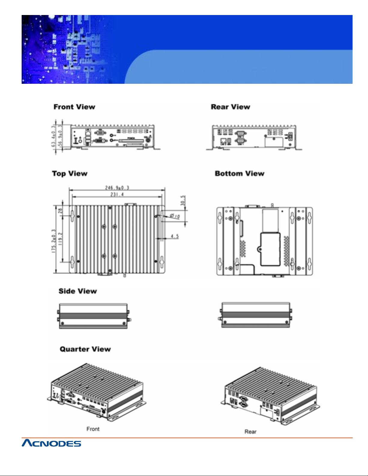
1-2 Case Illustration
FES7510
Fanless Embedded Controller comes with
Intel Celeron M ULV Processor
661 Brea Canyon Rd., Suite 3
Walnut, CA 91789
tel: 909.598.7388, fax: 909.598.0218, www.acnodes.com
© Copyright 2009 Acnodes, Inc.
All rights reserved. Product description and product specifications
are subject to change without notice. For latest product information,
please visit Acnodes’ web site at www.acnodes.com.
Page 10

1-3. SYSTEM SPECIFICATION
z CPU :
Socket 478 : Support Intel® Pentinum® M up to 2.0GHz
(FSB:533MHz/2MB L2 cache) /Celeron® M up to
1.86GHz(FSB:400MHz/1MB L2 cache)
Onboard : Support 1GHz w/o L2 cache, C-M 600MHz with L2 Cache
z SYSTEM CHIPSET :
Intel® 915GME+ICH6-M
z MEMORY :
DDR2/533 200Pin SO-DIMM , Max up to 2GB memory
FES7510
Fanless Embedded Controller comes with
Intel Celeron M ULV Processor
z CACHE :
Built-in CPU
z REAL-TIME CLOCK / CALENDAR :
256-byte battery backed CMOS RAM.
Hardware implementation to indicate century rollover
z BIOS :
Phoenix-AwardBIOS™ for plug & play function
Memory size with 4 MB, with VGA BIOS
z KEYBOARD/MOUSE CONNECTOR :
PS/2 connector for keyboard with mini DIN connector on rear Panel. (Y cable)
z UNIVERSAL SERIAL BUS :
6 x USB2.0, 2 x ports on rear panel, 4 x ports by pin header . (1x port used for M-system
embedded USB Flash disk)
661 Brea Canyon Rd., Suite 3
Walnut, CA 91789
tel: 909.598.7388, fax: 909.598.0218, www.acnodes.com
© Copyright 2009 Acnodes, Inc.
All rights reserved. Product description and product specifications
are subject to change without notice. For latest product information,
please visit Acnodes’ web site at www.acnodes.com.
Page 11

z DISPLAY :
Integrated in Intel 915GME chipset and SDVO solution
z IDE INTERFACE :
Compact Flash is connected at primary IDE Bus. Support to T ype II, Fixed disk firmware.
z SATA INTERFACE :
2 x SA T A connectors.
z LAN INTERFACE :
Dual ports. 1x 10/100Mbps, 1x 10/100/1000Mbps
z SOUND:
Realtek ALC655 with AC'97.
FES7510
Fanless Embedded Controller comes with
Intel Celeron M ULV Processor
Fully Compliant AC '97 Analog I/O Component
z SERIAL PORT :
Two high speed 16550 Comp atible UARTs with Send / Receive 16 Byte
FIFOs. COM1/2 for RS232
z HARDWARE MONITORING FUNCTION :
Monitor V oltage, CPU Temperature and Cooling Fan.
z LED INDICATOR :
Power LED, HDD LED and LAN LED
z DMA CONTROLLER :
82C37 x 2
z DMA CHANNELS :
7
661 Brea Canyon Rd., Suite 3
Walnut, CA 91789
tel: 909.598.7388, fax: 909.598.0218, www.acnodes.com
© Copyright 2009 Acnodes, Inc.
All rights reserved. Product description and product specifications
are subject to change without notice. For latest product information,
please visit Acnodes’ web site at www.acnodes.com.
Page 12

z INTERRUPT CONTROLLERS :
82C59 x 2
z INTERRUPT LEVELS :
15
z OPERATING TEMPERATURE :
When system is equipped with 2.5" hard disk 0 to 45 degree
When system is equipped with Compact Flash disk 0 to 45 degree
z INPUT POWER REQUIREMENT :
16-36V DC input , 100W.
z SYSTEM DIMENSION :
FES7510
Fanless Embedded Controller comes with
Intel Celeron M ULV Processor
216mm x 89.8mm x 175.2mm (with 3.5" HDD)
216mm x 56.9mm x 175.2mm (with 2.5' HDD)
z SYSTEM NET WEIGHT :
2.2 kg
1-4. SAFETY PRECAUTIONS
Follow the messages below to avoid your systems from damage:
1. Avoid your system from static electricity on all occasions.
2. Prevent electric shock. Don't touch any components of this card when the card is power-on. Always
disconnect power when the system is not in use.
3. Disconnect power when you change any hardware devices. For instance, when you connect a
jumper or install any cards, a surge of power may damage the electronic components or the whole
system.
661 Brea Canyon Rd., Suite 3
Walnut, CA 91789
tel: 909.598.7388, fax: 909.598.0218, www.acnodes.com
© Copyright 2009 Acnodes, Inc.
All rights reserved. Product description and product specifications
are subject to change without notice. For latest product information,
please visit Acnodes’ web site at www.acnodes.com.
Page 13

CHAPTER
FES7510
Fanless Embedded Controller comes with
Intel Celeron M ULV Processor
2
Hardware
Configuration
661 Brea Canyon Rd., Suite 3
Walnut, CA 91789
tel: 909.598.7388, fax: 909.598.0218, www.acnodes.com
© Copyright 2009 Acnodes, Inc.
All rights reserved. Product description and product specifications
are subject to change without notice. For latest product information,
please visit Acnodes’ web site at www.acnodes.com.
Page 14

FES7510
Fanless Embedded Controller comes with
Intel Celeron M ULV Processor
2-1. JUMPER & CONNECTOR QUICK REFERENCE TABLE
FSB Clock Frequency Selection …………………….… JP8
915GME Core Volt age Selection ……………………… JP3
Clear CMOS Data Selection …………………………… JP9
A TX Power Button ……………………………………. SW1, SW2
Keyboard or PS/2 Mouse Connector …………………... DIN1
Keyboard or PS/2 Mouse Selection ……………………. JP10
Reset Connector ………………………………………. JP6 (1-3)
Keylock Connector ……………………………………. JP6 (3-5)
External Buzzer Connector ……………………………. JP6 (4-6)
Power LED Connector ………………………………… LED1
Hard Disk Drive LED Connector ……………………… LED1
CPU FAN Connector ………………………………….. CPUF AN1
System FAN Connector ……………………………….. SYSF AN1
Compact Flash Connector …………………………….. CF1
COM Port Connector ………………………………….. COM1, COM2
COM1/2 RI & Volt age Selection ……………………… JP2
VGA Connector ……………………………………….. JDVIVGA1
Serial AT A Connector ………………………………… SA TA1, SA TA2
DVI Connector ………………………………………… JDVIVGA1
Universal Serial Bus Connector ……………………….. USB1, USB2, USB3
Giga LAN Connector ………………………………….. USB_RJG1, LAN1
A TX Power Connector ………………………………… PW1
A TX/ AT Power Selection …………………………….. JP11, JP1
Memory Installation …………………………………… DIMM1
Reset/ NMI Selection ………………………………….. JP7
Sound Connector ………………………………………. JAUDIO1
LINE-IN or MIC-IN Selection ………………………… JP4
1394 Connector ……………………………………….. PORT1
Digital I/O Port ………………………………………… CN1
L VDS Connector .......................................................... L VDS1
L VDS Panel Volt age Selection ...................................... JP5
Inverter Connector .......................................................... INV1
© Copyright 2009 Acnodes, Inc.
661 Brea Canyon Rd., Suite 3
Walnut, CA 91789
tel: 909.598.7388, fax: 909.598.0218, www.acnodes.com
All rights reserved. Product description and product specifications
are subject to change without notice. For latest product information,
please visit Acnodes’ web site at www.acnodes.com.
Page 15
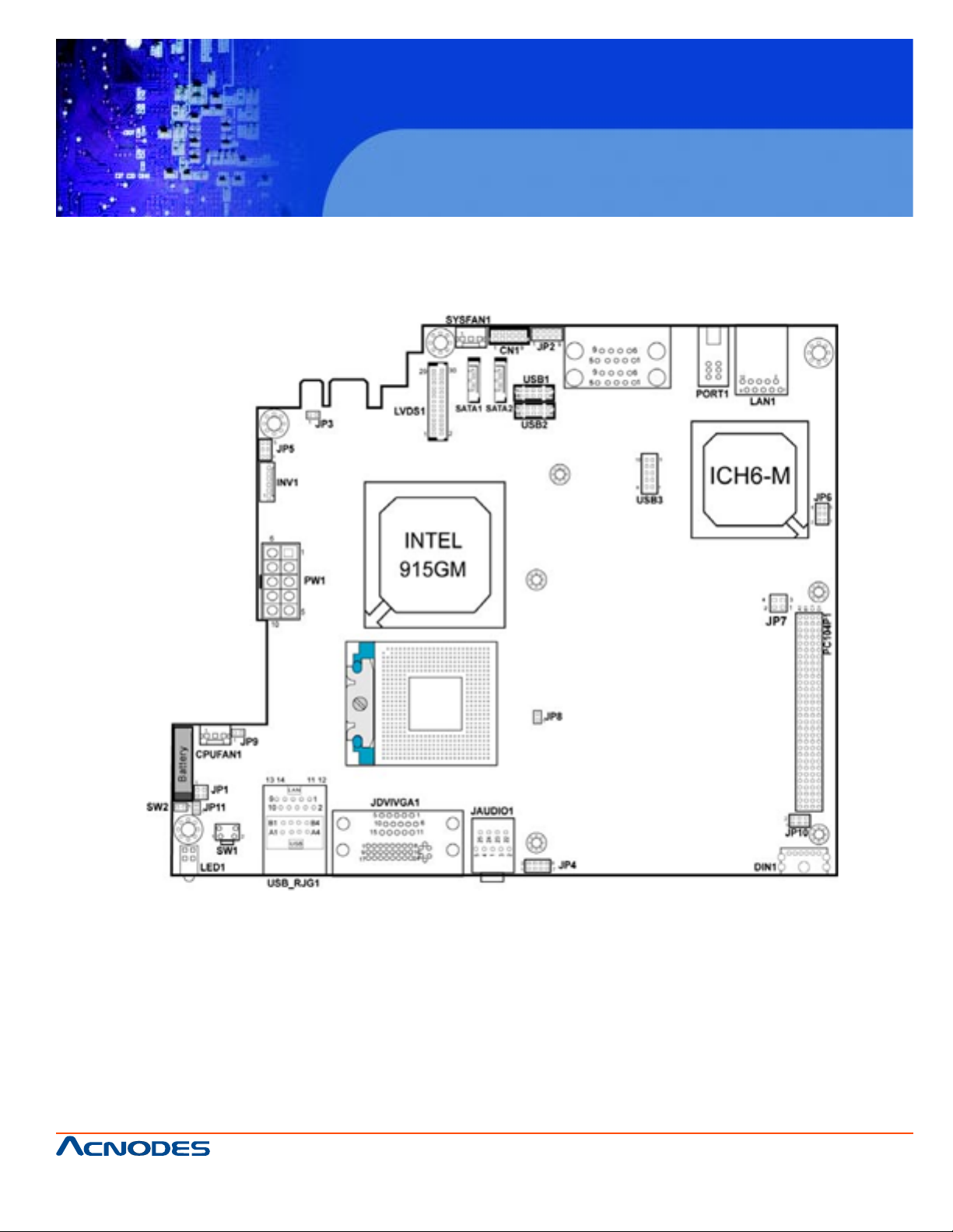
2-2 Component Locations
FES7510
Fanless Embedded Controller comes with
Intel Celeron M ULV Processor
661 Brea Canyon Rd., Suite 3
Walnut, CA 91789
tel: 909.598.7388, fax: 909.598.0218, www.acnodes.com
© Copyright 2009 Acnodes, Inc.
All rights reserved. Product description and product specifications
are subject to change without notice. For latest product information,
please visit Acnodes’ web site at www.acnodes.com.
Page 16
FES7510
Fanless Embedded Controller comes with
Intel Celeron M ULV Processor
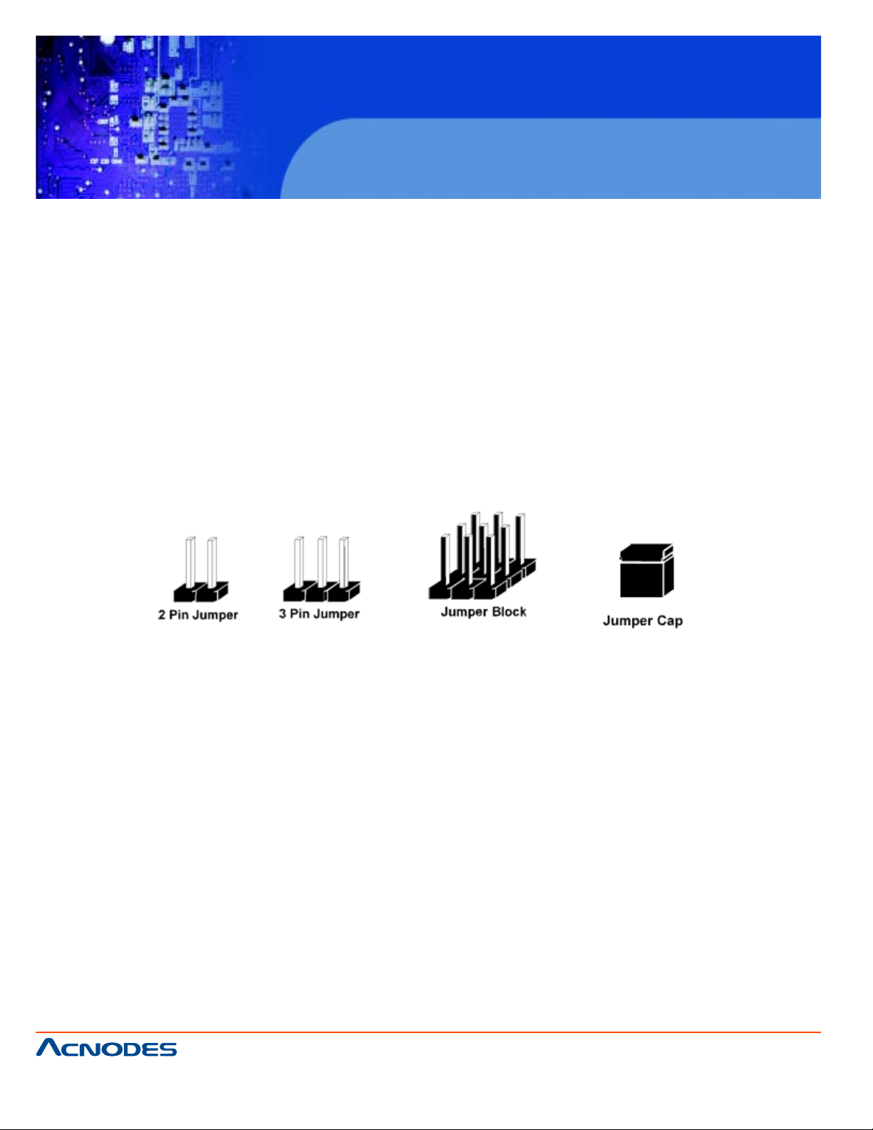
2-3. HOW TO SET THE JUMPERS
Y ou can configure your board by setting jumpers. Jumper is consists of two or three met al pins with a
plastic base mounted on the card, and by using a small plastic "cap", Also known as the jumper cap
(with a metal contact inside), you are able to connect the pins. So you can set-up your hardware
configuration by "open" or "close" pins.
The jumper can be combined into sets that called jumper blocks. When the jumpers are all in the block,
you have to put them together to set up the hardware configuration. The figure below shows how this
looks like.
JUMPERS AND CAPS
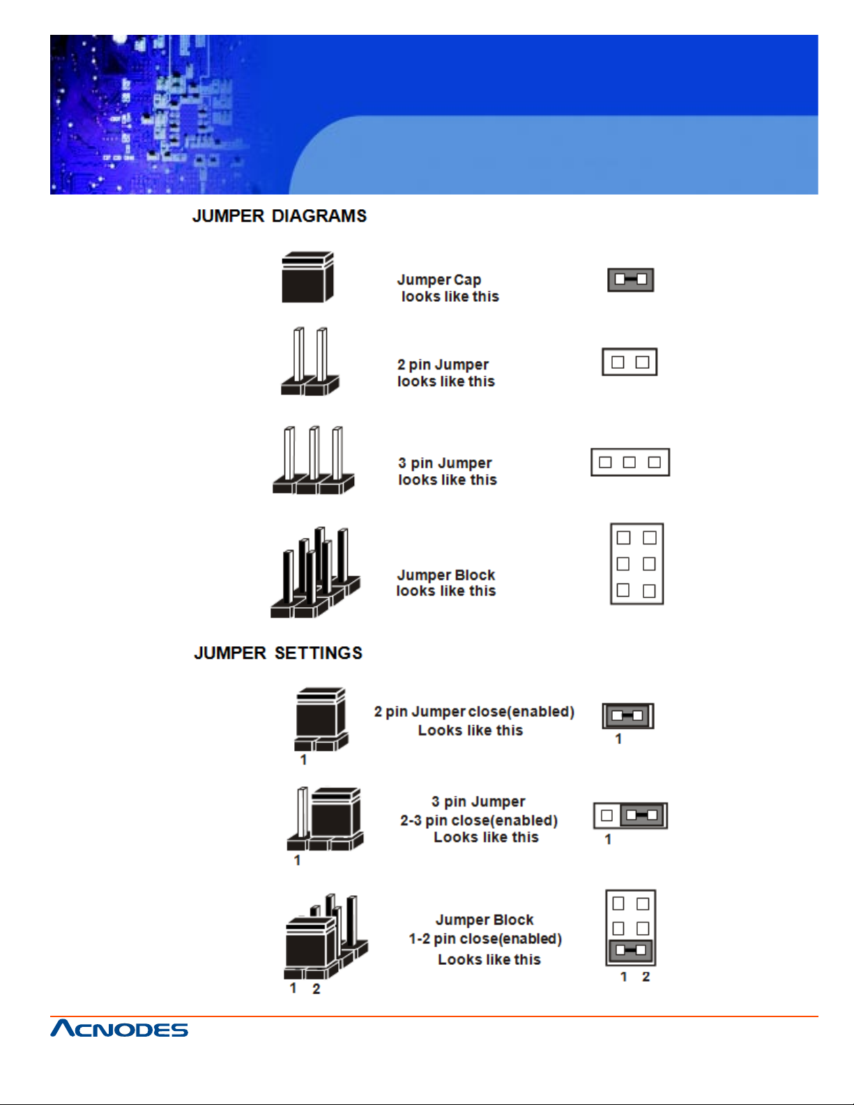
If a jumper has three pins (for examples, labelled PIN1, PIN2, and PIN3), Y ou can connect PIN1 & PIN2
to create one setting and shorting. Y ou can either connect PIN2 & PIN3 to create another setting. The
same jumper diagrams are applied all through this manual. The figure below shows what the manual
diagrams look and what they represent.
© Copyright 2009 Acnodes, Inc.
661 Brea Canyon Rd., Suite 3
Walnut, CA 91789
tel: 909.598.7388, fax: 909.598.0218, www.acnodes.com
All rights reserved. Product description and product specifications
are subject to change without notice. For latest product information,
please visit Acnodes’ web site at www.acnodes.com.
Page 17
FES7510
Fanless Embedded Controller comes with
Intel Celeron M ULV Processor
661 Brea Canyon Rd., Suite 3
Walnut, CA 91789
tel: 909.598.7388, fax: 909.598.0218, www.acnodes.com
© Copyright 2009 Acnodes, Inc.
All rights reserved. Product description and product specifications
are subject to change without notice. For latest product information,
please visit Acnodes’ web site at www.acnodes.com.
Page 18
FES7510
Fanless Embedded Controller comes with
Intel Celeron M ULV Processor
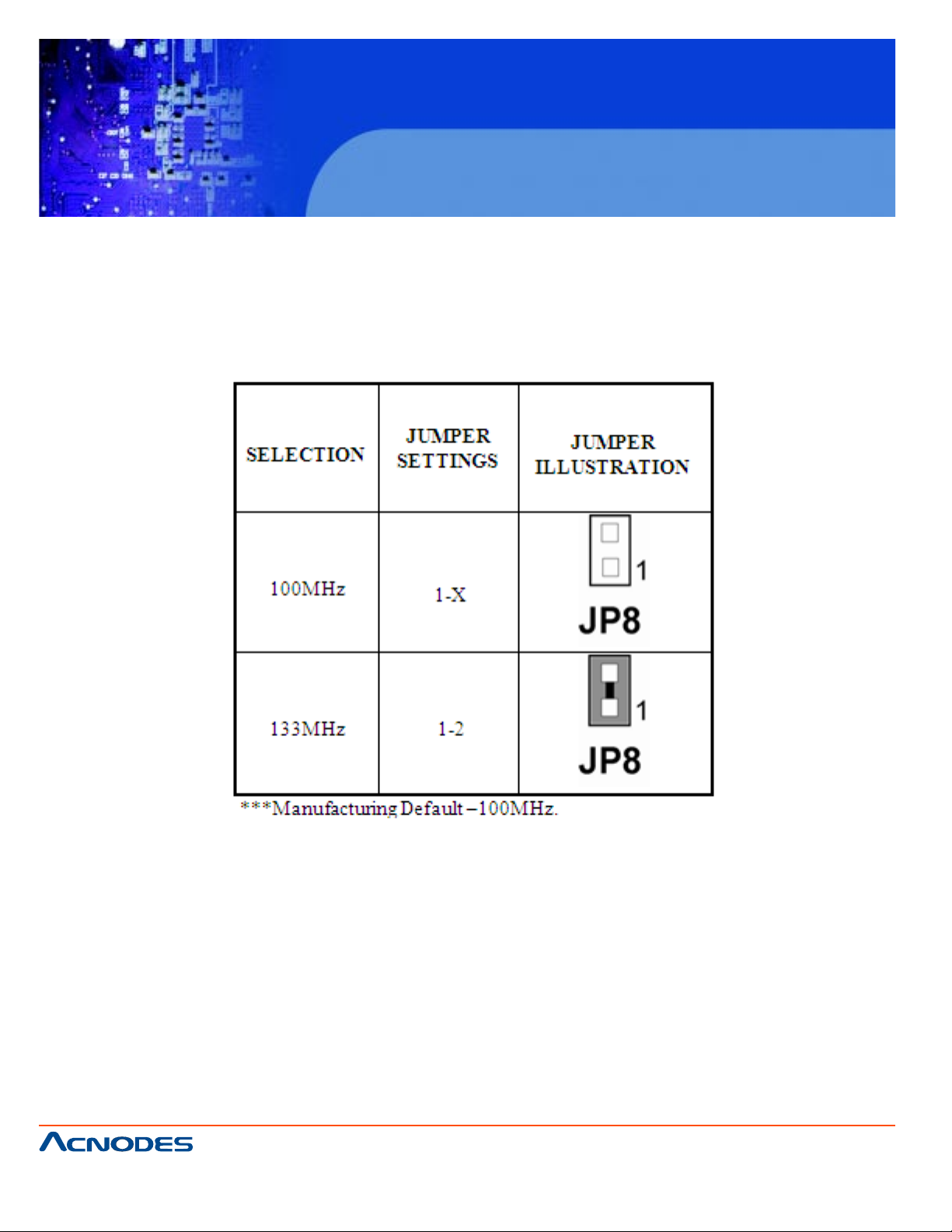
2-4 FSB CLOCK FREQUENCY SELECTION
JP1: FSB Clock Frequency selection
The selections are as follows:
661 Brea Canyon Rd., Suite 3
Walnut, CA 91789
tel: 909.598.7388, fax: 909.598.0218, www.acnodes.com
© Copyright 2009 Acnodes, Inc.
All rights reserved. Product description and product specifications
are subject to change without notice. For latest product information,
please visit Acnodes’ web site at www.acnodes.com.
Page 19
FES7510
Fanless Embedded Controller comes with
Intel Celeron M ULV Processor
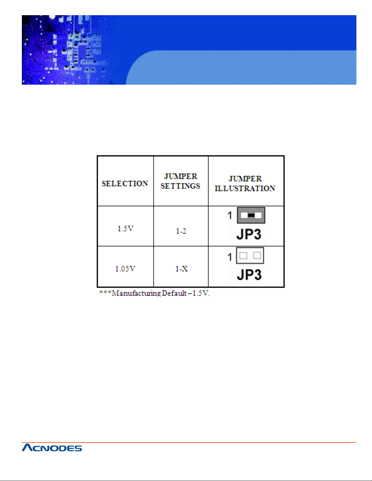
2-5. 915GME CORE VOLTAGE SELECTION
JP3: 915 GME Core Volt age Selection
The selections are as follows:
661 Brea Canyon Rd., Suite 3
Walnut, CA 91789
tel: 909.598.7388, fax: 909.598.0218, www.acnodes.com
© Copyright 2009 Acnodes, Inc.
All rights reserved. Product description and product specifications
are subject to change without notice. For latest product information,
please visit Acnodes’ web site at www.acnodes.com.
Page 20
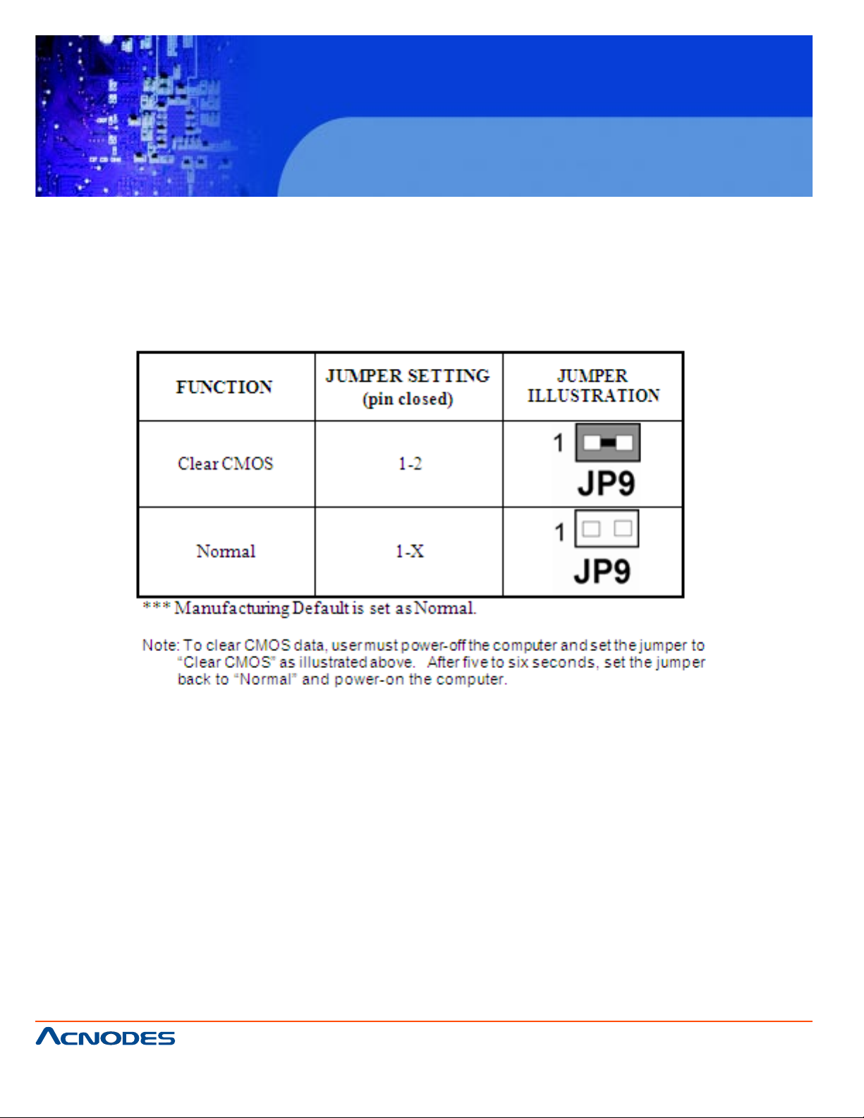
2.6 CLEAR CMOS DATA SELECTION
JP9: Clear CMOS Data Selection
The selection are as follows :
FES7510
Fanless Embedded Controller comes with
Intel Celeron M ULV Processor
661 Brea Canyon Rd., Suite 3
Walnut, CA 91789
tel: 909.598.7388, fax: 909.598.0218, www.acnodes.com
© Copyright 2009 Acnodes, Inc.
All rights reserved. Product description and product specifications
are subject to change without notice. For latest product information,
please visit Acnodes’ web site at www.acnodes.com.
Page 21
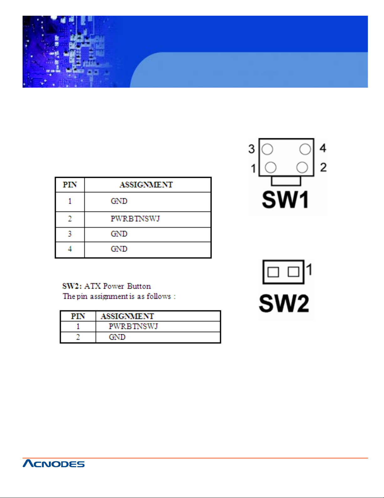
2-7 ATX POWER BUTTON
SW1 : Power button switch
The pin assignments are as follows :
FES7510
Fanless Embedded Controller comes with
Intel Celeron M ULV Processor
661 Brea Canyon Rd., Suite 3
Walnut, CA 91789
tel: 909.598.7388, fax: 909.598.0218, www.acnodes.com
© Copyright 2009 Acnodes, Inc.
All rights reserved. Product description and product specifications
are subject to change without notice. For latest product information,
please visit Acnodes’ web site at www.acnodes.com.
Page 22
FES7510
Fanless Embedded Controller comes with
Intel Celeron M ULV Processor
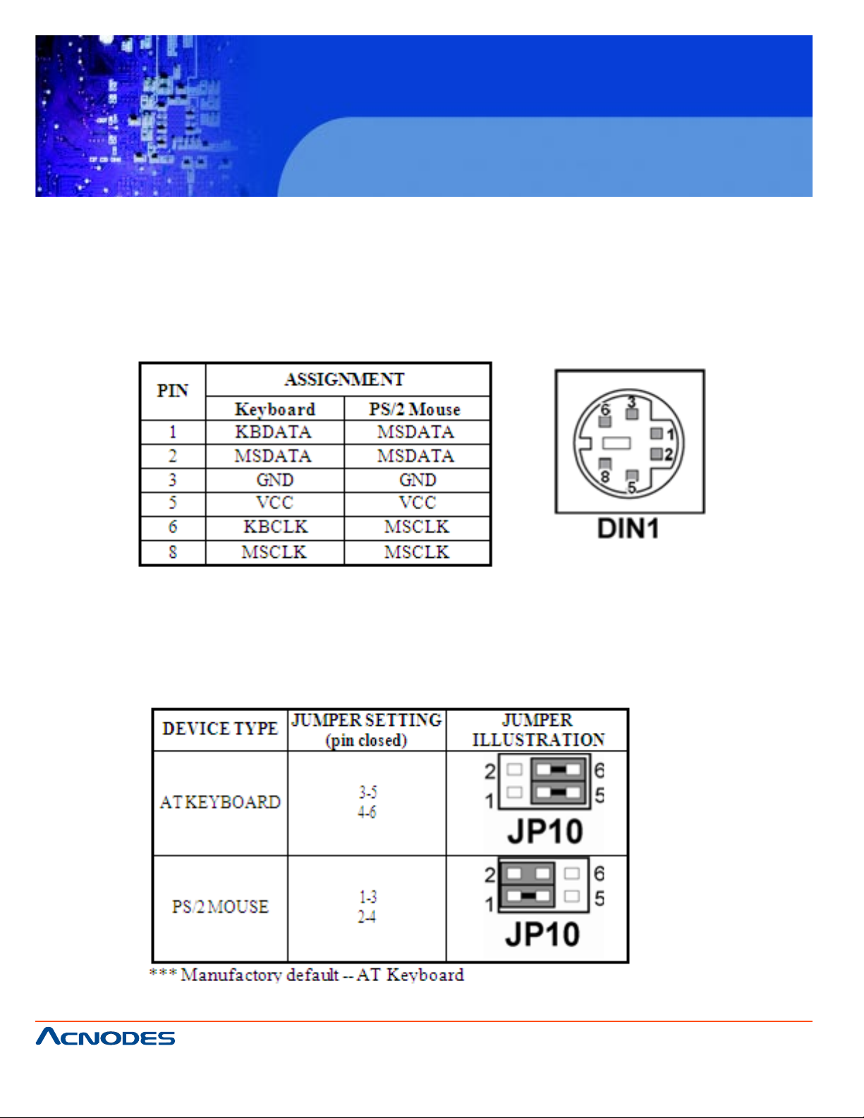
2-8 KEYBOARD OR PS/2 MOUSE CONNECTOR
DIN1: Keyboard or PS/2 Mouse Connector
DIN connector can support keyboard, Y -cable, or PS/2 Mouse, user may select the
right device to used on "Keyboard or PS/2 Mouse Selection". The pin assignments
are as follows :
2-9. KEYBOARD OR PS/2 MOUSE SELECTION
JP10 : Keyboard or PS/2 Mouse Selection
For Y -Cable user , please set the jumper same as A T keyboard. The jumper settings are as follows:
661 Brea Canyon Rd., Suite 3
Walnut, CA 91789
tel: 909.598.7388, fax: 909.598.0218, www.acnodes.com
© Copyright 2009 Acnodes, Inc.
All rights reserved. Product description and product specifications
are subject to change without notice. For latest product information,
please visit Acnodes’ web site at www.acnodes.com.
Page 23
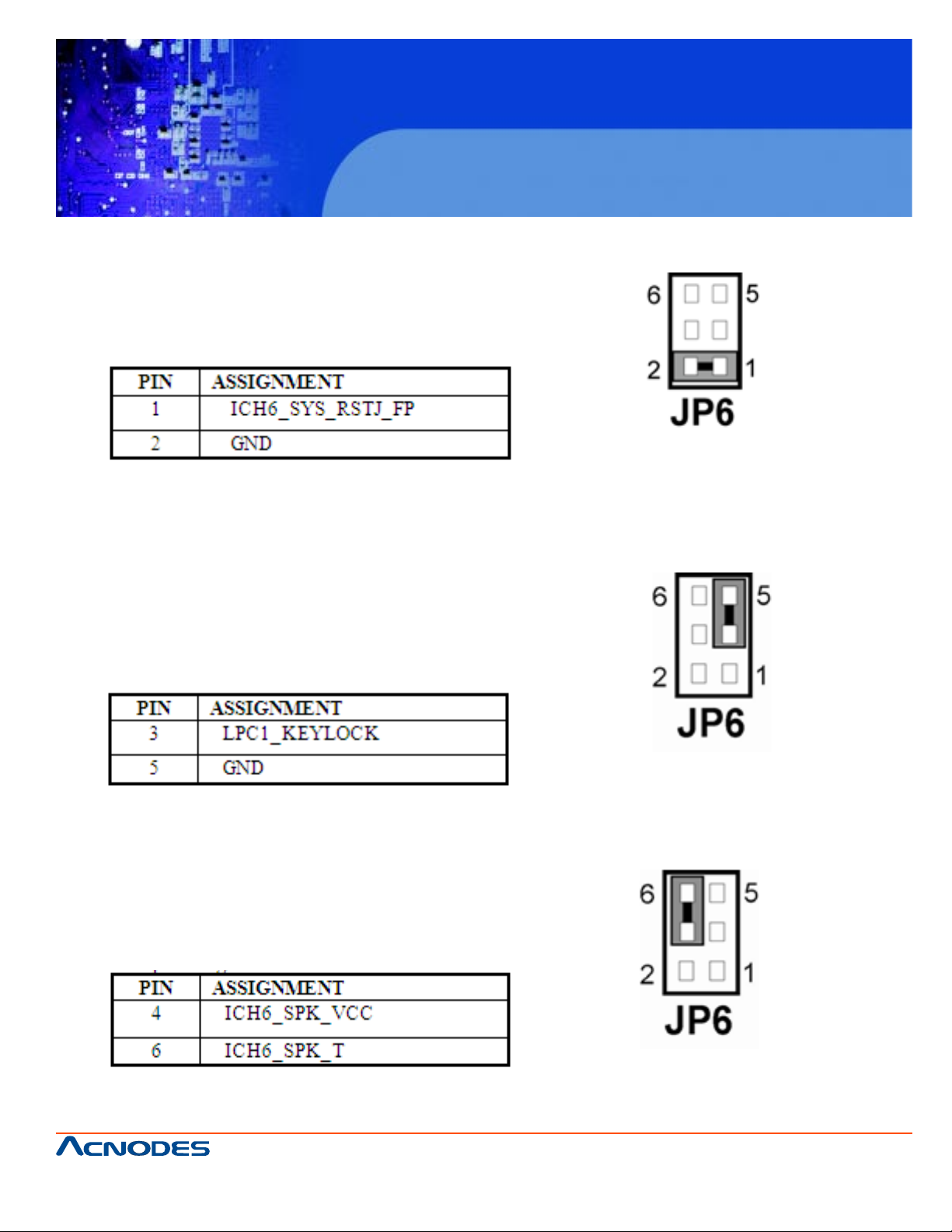
2.10 RESET CONNECTOR
JP6(1-2) : Reset Connector
The pin assignment is as follows:
2-11. KEYLOCK CONNECTOR
FES7510
Fanless Embedded Controller comes with
Intel Celeron M ULV Processor
JP6 (3-5) : Keylock Connector
The pin assignment is as follows:
2-12. EXTERNAL BUZZER CONNECTOR
JP6 (4-6) : External buzzer connector
The pin assignment is as follows:
661 Brea Canyon Rd., Suite 3
Walnut, CA 91789
tel: 909.598.7388, fax: 909.598.0218, www.acnodes.com
© Copyright 2009 Acnodes, Inc.
All rights reserved. Product description and product specifications
are subject to change without notice. For latest product information,
please visit Acnodes’ web site at www.acnodes.com.
Page 24
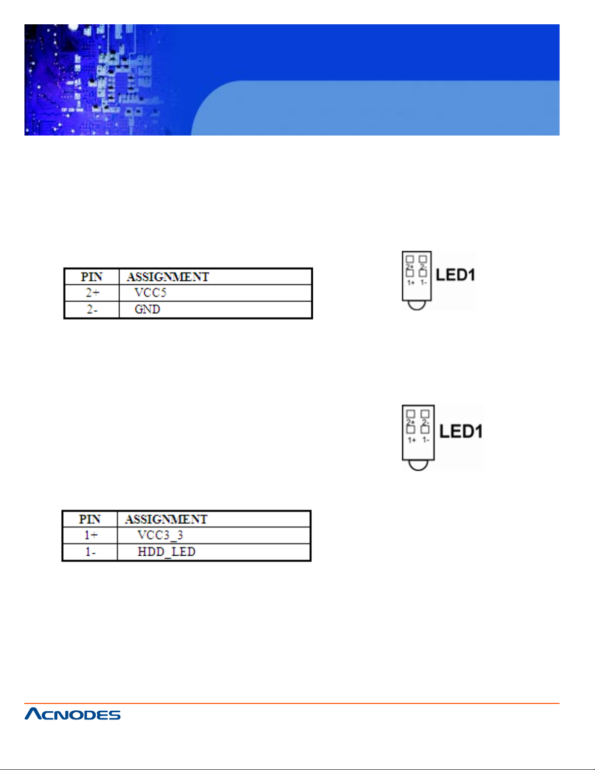
2.13 POWER LED CONNECTOR
LED1 : Power LED Connector
The pin assignment is as follows :
FES7510
Fanless Embedded Controller comes with
Intel Celeron M ULV Processor
2.14 HARD DISK DRIVE LED CONNECTOR
LED1 : Hard Disk Drive LED Connector
The pin assignment is as follows :
661 Brea Canyon Rd., Suite 3
Walnut, CA 91789
tel: 909.598.7388, fax: 909.598.0218, www.acnodes.com
© Copyright 2009 Acnodes, Inc.
All rights reserved. Product description and product specifications
are subject to change without notice. For latest product information,
please visit Acnodes’ web site at www.acnodes.com.
Page 25
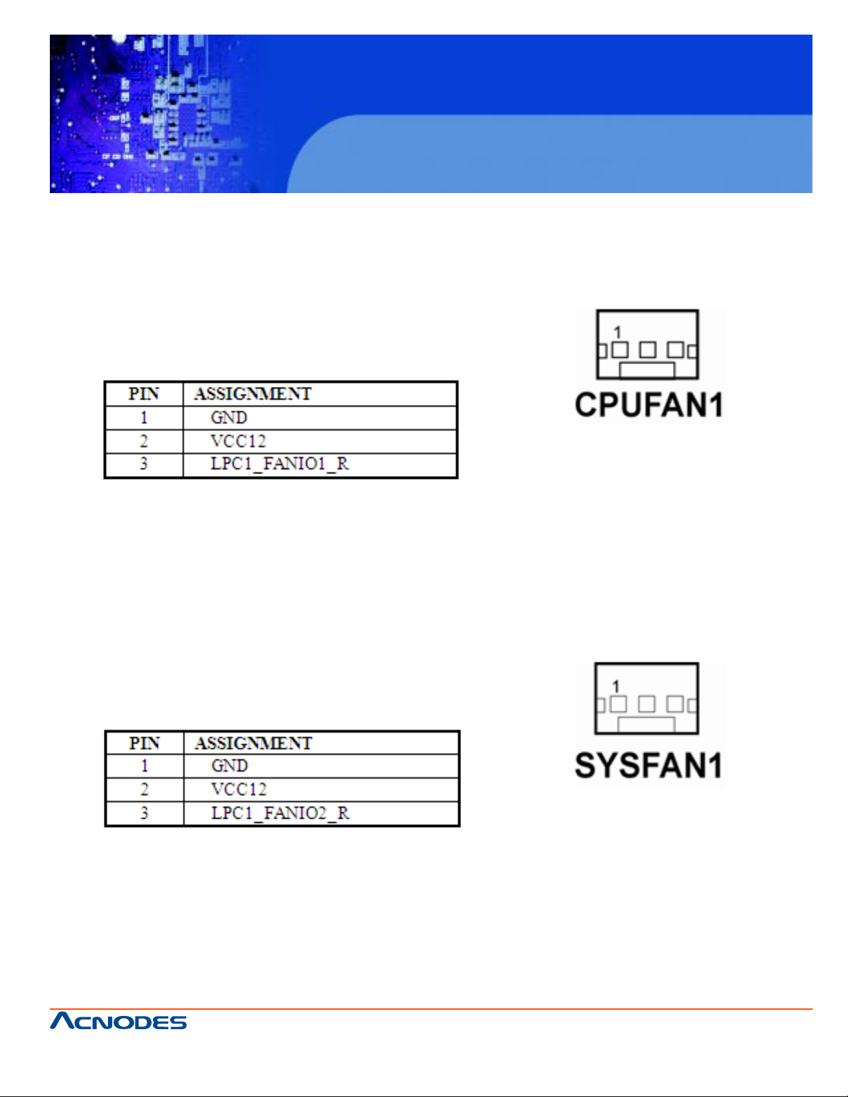
2.15 CPU FAN CONNECTOR
CPUFAN1: CPU FAN Connector
The pin assignment are as follows:
FES7510
Fanless Embedded Controller comes with
Intel Celeron M ULV Processor
2.16 SYSTEM FAN CONNECTOR
SYSFAN1 : System Fan Connector
The pin assignment is as follows:
661 Brea Canyon Rd., Suite 3
Walnut, CA 91789
tel: 909.598.7388, fax: 909.598.0218, www.acnodes.com
© Copyright 2009 Acnodes, Inc.
All rights reserved. Product description and product specifications
are subject to change without notice. For latest product information,
please visit Acnodes’ web site at www.acnodes.com.
Page 26
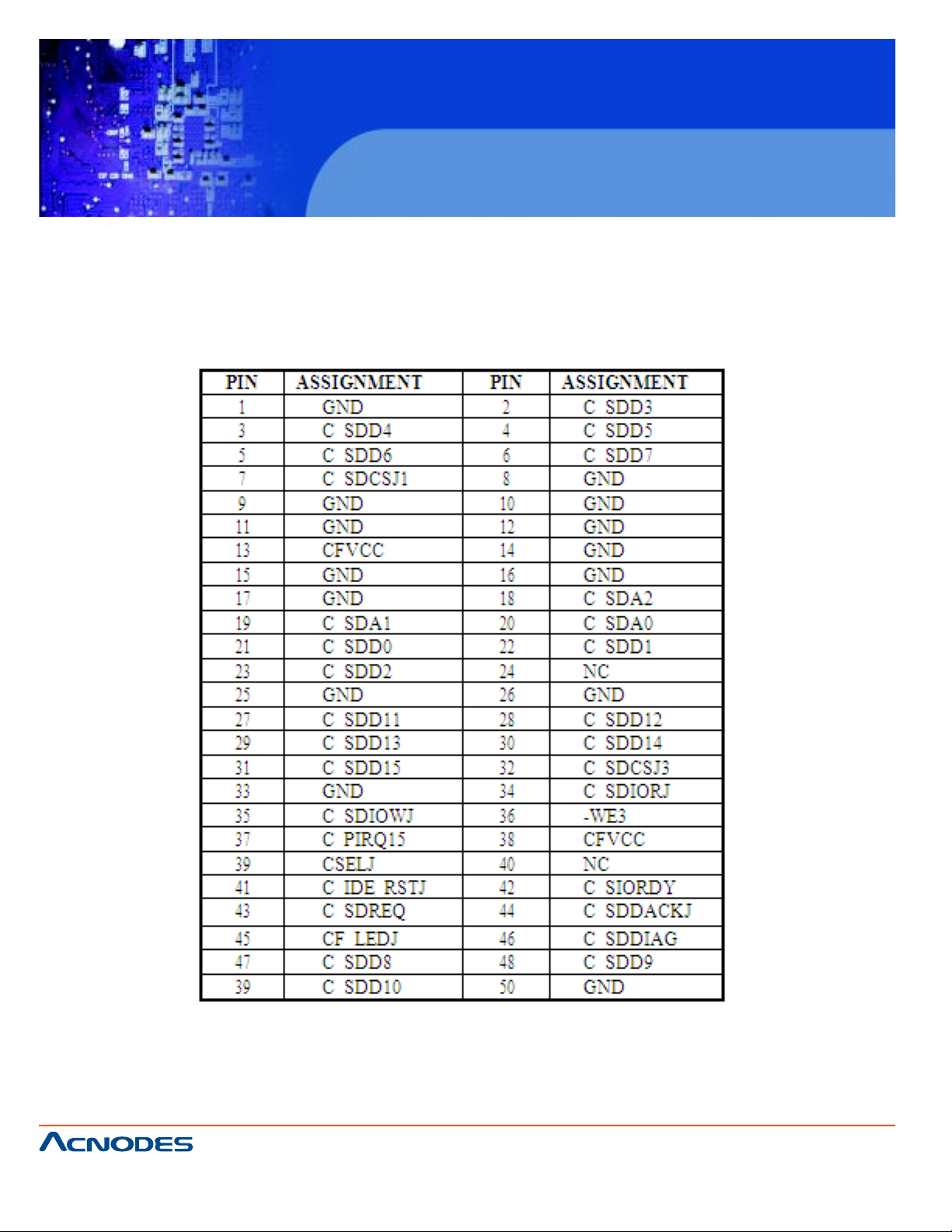
2.17 COMPACT FLASH CONNECTOR
CF1: Compact Flash Connector
The selections are as follows:
FES7510
Fanless Embedded Controller comes with
Intel Celeron M ULV Processor
661 Brea Canyon Rd., Suite 3
Walnut, CA 91789
tel: 909.598.7388, fax: 909.598.0218, www.acnodes.com
© Copyright 2009 Acnodes, Inc.
All rights reserved. Product description and product specifications
are subject to change without notice. For latest product information,
please visit Acnodes’ web site at www.acnodes.com.
Page 27
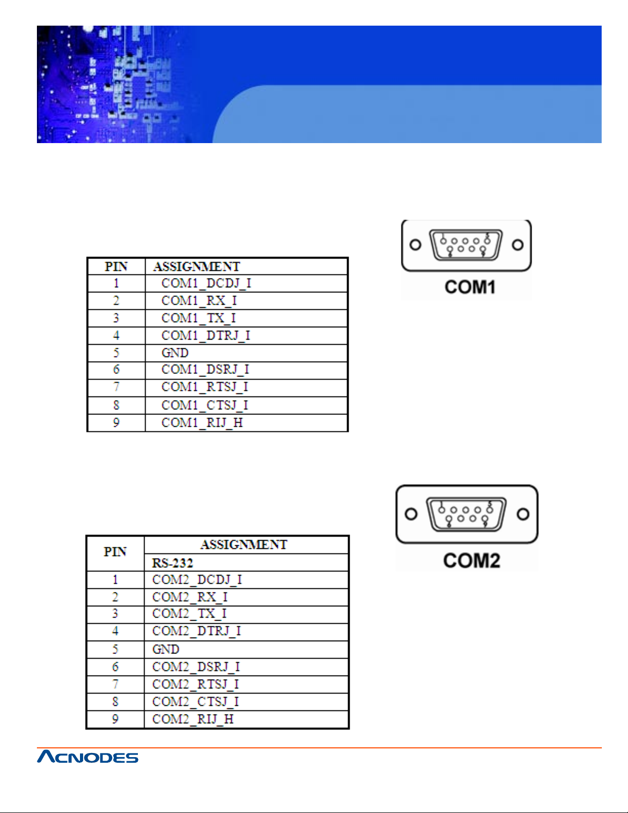
2.18 COM PORT CONNECTOR
COM1: COM1 Connector
COM1 is fixed as RS-232
The pin assignments are as follows:
FES7510
Fanless Embedded Controller comes with
Intel Celeron M ULV Processor
COM2: COM2 Connector
COM2 is fixed as RS-232
The pin assignments are as follows:
661 Brea Canyon Rd., Suite 3
Walnut, CA 91789
tel: 909.598.7388, fax: 909.598.0218, www.acnodes.com
© Copyright 2009 Acnodes, Inc.
All rights reserved. Product description and product specifications
are subject to change without notice. For latest product information,
please visit Acnodes’ web site at www.acnodes.com.
Page 28
FES7510
Fanless Embedded Controller comes with
Intel Celeron M ULV Processor
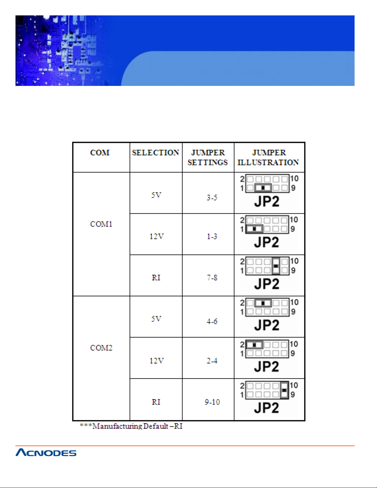
2-19. COM1/2 RI & VOLTAGE SELECTION
JP2: COM1/2 RI & V olt age Selection
The selections are as follows:
661 Brea Canyon Rd., Suite 3
Walnut, CA 91789
tel: 909.598.7388, fax: 909.598.0218, www.acnodes.com
© Copyright 2009 Acnodes, Inc.
All rights reserved. Product description and product specifications
are subject to change without notice. For latest product information,
please visit Acnodes’ web site at www.acnodes.com.
Page 29
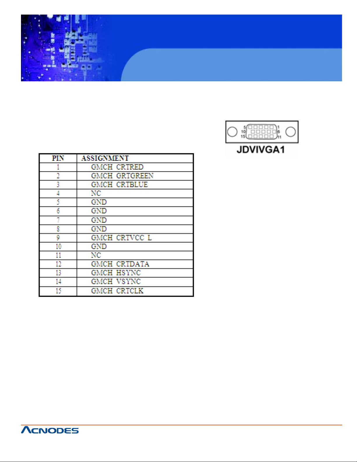
2-20. VGA CONNECTOR
JDVIVGA1: VGA Connector
The pin assignments are as follows:
FES7510
Fanless Embedded Controller comes with
Intel Celeron M ULV Processor
661 Brea Canyon Rd., Suite 3
Walnut, CA 91789
tel: 909.598.7388, fax: 909.598.0218, www.acnodes.com
© Copyright 2009 Acnodes, Inc.
All rights reserved. Product description and product specifications
are subject to change without notice. For latest product information,
please visit Acnodes’ web site at www.acnodes.com.
Page 30
FES7510
Fanless Embedded Controller comes with
Intel Celeron M ULV Processor
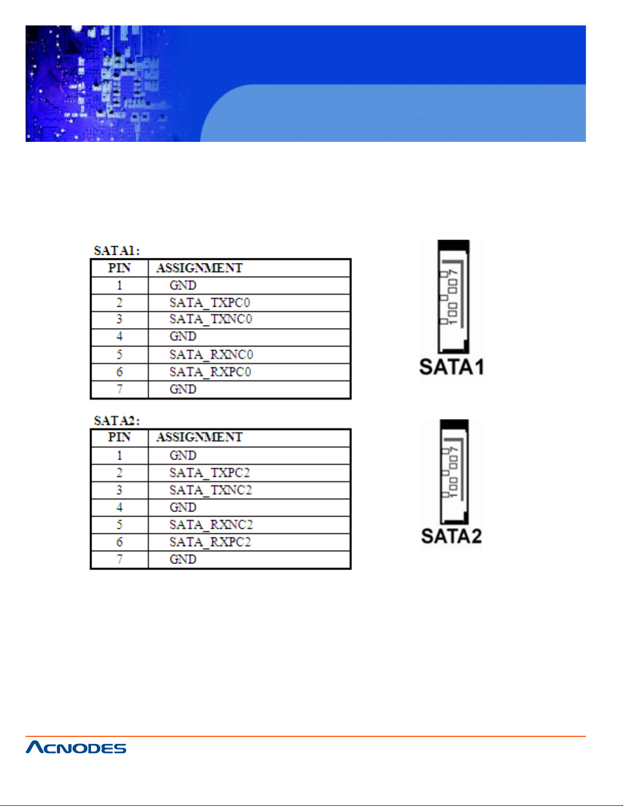
2-21. SERIAL ATA CONNECTOR
SA T A1, SA T A2: The possesses two Serial A T A Connector .
The pin assignments are as follows:
661 Brea Canyon Rd., Suite 3
Walnut, CA 91789
tel: 909.598.7388, fax: 909.598.0218, www.acnodes.com
© Copyright 2009 Acnodes, Inc.
All rights reserved. Product description and product specifications
are subject to change without notice. For latest product information,
please visit Acnodes’ web site at www.acnodes.com.
Page 31

2-22. DVI CONNECTOR
JDVIVGA1 : DVI Connector.
The pin assignments are as follows:
FES7510
Fanless Embedded Controller comes with
Intel Celeron M ULV Processor
661 Brea Canyon Rd., Suite 3
Walnut, CA 91789
tel: 909.598.7388, fax: 909.598.0218, www.acnodes.com
© Copyright 2009 Acnodes, Inc.
All rights reserved. Product description and product specifications
are subject to change without notice. For latest product information,
please visit Acnodes’ web site at www.acnodes.com.
Page 32

FES7510
Fanless Embedded Controller comes with
Intel Celeron M ULV Processor
2-23. UNIVERSAL SERIAL BUS CONNECTOR
USB1: Universal Serial Bus Connector
The pin assignments are as follows:
661 Brea Canyon Rd., Suite 3
Walnut, CA 91789
tel: 909.598.7388, fax: 909.598.0218, www.acnodes.com
© Copyright 2009 Acnodes, Inc.
All rights reserved. Product description and product specifications
are subject to change without notice. For latest product information,
please visit Acnodes’ web site at www.acnodes.com.
Page 33

USB3: Universal Serial Bus Connector
The pin assignments are as follows:
FES7510
Fanless Embedded Controller comes with
Intel Celeron M ULV Processor
661 Brea Canyon Rd., Suite 3
Walnut, CA 91789
tel: 909.598.7388, fax: 909.598.0218, www.acnodes.com
© Copyright 2009 Acnodes, Inc.
All rights reserved. Product description and product specifications
are subject to change without notice. For latest product information,
please visit Acnodes’ web site at www.acnodes.com.
Page 34

2-24. GIGA LAN CONNECTOR
USB_RJG1 : Giga Lan Connector
The pin assignments are as follows:
FES7510
Fanless Embedded Controller comes with
Intel Celeron M ULV Processor
661 Brea Canyon Rd., Suite 3
Walnut, CA 91789
tel: 909.598.7388, fax: 909.598.0218, www.acnodes.com
© Copyright 2009 Acnodes, Inc.
All rights reserved. Product description and product specifications
are subject to change without notice. For latest product information,
please visit Acnodes’ web site at www.acnodes.com.
Page 35

LAN1 : LAN Connector
The pin assignments are as follows:
FES7510
Fanless Embedded Controller comes with
Intel Celeron M ULV Processor
661 Brea Canyon Rd., Suite 3
Walnut, CA 91789
tel: 909.598.7388, fax: 909.598.0218, www.acnodes.com
© Copyright 2009 Acnodes, Inc.
All rights reserved. Product description and product specifications
are subject to change without notice. For latest product information,
please visit Acnodes’ web site at www.acnodes.com.
Page 36

2-25. ATX POWER CONNECTOR
PW1 : A TX Power Connector
The pin assignments are as follows:
FES7510
Fanless Embedded Controller comes with
Intel Celeron M ULV Processor
2-26. ATX / AT POWER SELECTION
JP11 : A T / ATX Power Selection
The selections are as follows:
661 Brea Canyon Rd., Suite 3
Walnut, CA 91789
tel: 909.598.7388, fax: 909.598.0218, www.acnodes.com
© Copyright 2009 Acnodes, Inc.
All rights reserved. Product description and product specifications
are subject to change without notice. For latest product information,
please visit Acnodes’ web site at www.acnodes.com.
Page 37

FES7510
Fanless Embedded Controller comes with
Intel Celeron M ULV Processor
2-27. MEMORY INSTALLATION
PROX-7510LF CPU Card can support up to 1GB in one SO-DIMM sockets.
DRAM BANK CONFIGURATION
2-28. RESET/NMI SELECTION
JP7 : Reset/NMI Watchdog Selection
The selections are as follows:
661 Brea Canyon Rd., Suite 3
Walnut, CA 91789
tel: 909.598.7388, fax: 909.598.0218, www.acnodes.com
© Copyright 2009 Acnodes, Inc.
All rights reserved. Product description and product specifications
are subject to change without notice. For latest product information,
please visit Acnodes’ web site at www.acnodes.com.
Page 38

2-29. SOUND CONNECTOR
JAUDIO1 : Sound Connector.
The pin assignments are as follows :
Line-out
FES7510
Fanless Embedded Controller comes with
Intel Celeron M ULV Processor
2-29-1. LINE-IN or MIC-IN SELECTION
JP4 : Line-In or MIC-In Selection
The selections are as follows:
661 Brea Canyon Rd., Suite 3
Walnut, CA 91789
tel: 909.598.7388, fax: 909.598.0218, www.acnodes.com
© Copyright 2009 Acnodes, Inc.
All rights reserved. Product description and product specifications
are subject to change without notice. For latest product information,
please visit Acnodes’ web site at www.acnodes.com.
Page 39

2-30. 1394 CONNECTOR
PROT1 : 1394 connector
The pin assignments are as follows:
FES7510
Fanless Embedded Controller comes with
Intel Celeron M ULV Processor
2-31. DIGIT AL I/O PORT
CN1: Digital Input/Output Port.
The pin assignments are as follows:
661 Brea Canyon Rd., Suite 3
Walnut, CA 91789
tel: 909.598.7388, fax: 909.598.0218, www.acnodes.com
© Copyright 2009 Acnodes, Inc.
All rights reserved. Product description and product specifications
are subject to change without notice. For latest product information,
please visit Acnodes’ web site at www.acnodes.com.
Page 40

2-32. LVDS CONNECTOR
LVDS1 : LVDS Connector.
The pin assignments are as follows:
FES7510
Fanless Embedded Controller comes with
Intel Celeron M ULV Processor
661 Brea Canyon Rd., Suite 3
Walnut, CA 91789
tel: 909.598.7388, fax: 909.598.0218, www.acnodes.com
© Copyright 2009 Acnodes, Inc.
All rights reserved. Product description and product specifications
are subject to change without notice. For latest product information,
please visit Acnodes’ web site at www.acnodes.com.
Page 41

FES7510
Fanless Embedded Controller comes with
Intel Celeron M ULV Processor
2-33. LVDS PANEL VOLTAGE SELECTION
JP5 : L VDS Panel Voltage Selection.
The selections are as follows:
2-34. INVERTER CONNECTOR
INV1 : Inverter Connector
The pin assignment is as follows:
661 Brea Canyon Rd., Suite 3
Walnut, CA 91789
tel: 909.598.7388, fax: 909.598.0218, www.acnodes.com
© Copyright 2009 Acnodes, Inc.
All rights reserved. Product description and product specifications
are subject to change without notice. For latest product information,
please visit Acnodes’ web site at www.acnodes.com.
Page 42

CHPATER
FES7510
Fanless Embedded Controller comes with
Intel Celeron M ULV Processor
3
Software
Utilities
661 Brea Canyon Rd., Suite 3
Walnut, CA 91789
tel: 909.598.7388, fax: 909.598.0218, www.acnodes.com
© Copyright 2009 Acnodes, Inc.
All rights reserved. Product description and product specifications
are subject to change without notice. For latest product information,
please visit Acnodes’ web site at www.acnodes.com.
Page 43

FES7510
Fanless Embedded Controller comes with
Intel Celeron M ULV Processor
3.1 Introduction
Enclosed with our FES-7510 package is our driver utility , which may comes in a form of a CD ROM
disc or floppy diskettes. For CD ROM disc user, you will only need some of the files cont ained in the
CD ROM disc, please kindly refer to the following chart:
661 Brea Canyon Rd., Suite 3
Walnut, CA 91789
tel: 909.598.7388, fax: 909.598.0218, www.acnodes.com
© Copyright 2009 Acnodes, Inc.
All rights reserved. Product description and product specifications
are subject to change without notice. For latest product information,
please visit Acnodes’ web site at www.acnodes.com.
Page 44

FES7510
Fanless Embedded Controller comes with
Intel Celeron M ULV Processor
3.2 VGA Driver Utility
The VGA interface embedded with our FES-7510 can support a wide range of display . You can display CRT, L VDS simultaneously with the same mode.
3-2-1. Installation of VGA Driver:
T o install the VGA Driver , simply follow the following steps:
1. Place insert the Utility Disk into Floppy Disk Drive A/B or CD ROM drive.
2. Under Windows 2000/XP system, go to the directory where VGA driver is located.
3. Click Setup.exe file for VGA driver installation.
4. Follow the instructions on the screen to complete the installation.
5. Once installation is completed, shut down the system and restart in order for the changes to
take effect.
© Copyright 2009 Acnodes, Inc.
661 Brea Canyon Rd., Suite 3
Walnut, CA 91789
tel: 909.598.7388, fax: 909.598.0218, www.acnodes.com
All rights reserved. Product description and product specifications
are subject to change without notice. For latest product information,
please visit Acnodes’ web site at www.acnodes.com.
Page 45

FES7510
Fanless Embedded Controller comes with
Intel Celeron M ULV Processor
3-3. FLASH BIOS UPDATE
3-3-1. System BIOS Update:
Users of FES-7510 can use the program "Awdflash.exe" contained in the Utility Disk for system BIOS and
VGA BIOS update.
3-3-2. To update VGA BIOS for LCD Flat Panel Display:
As FES-7510 user, you have to update the VGA BIOS for your specific LCD flat p anel you are going to
use. For doing this, you need two files. One is the "Awdflash.exe" file and the other is the VGA BIOS for A TI
Rage Mobility M6 file for LCD panel display . Both file must be provided by the vendor or manufacturer. When you get these two files ready , follow the following step s for updating your VGA BIOS:
1. Install "Awdflash.exe" from Utility Disk to Drive C.
2. Insert the VGA BIOS file you have obtained from the vendor .
Type the path to Awdflash.exe and execute the VGA BIOS update with file 7510xxxx.bin
3. C:\UTIL\AWDFLASH>AWDFLASH 7510xxxx.bin
4. The screen will display as the table fount on the next page:
If you want to save up the original BIOS, enter "Y" and press < Enter >.
If you choose "N", the following table will appear on screen.
661 Brea Canyon Rd., Suite 3
Walnut, CA 91789
tel: 909.598.7388, fax: 909.598.0218, www.acnodes.com
© Copyright 2009 Acnodes, Inc.
All rights reserved. Product description and product specifications
are subject to change without notice. For latest product information,
please visit Acnodes’ web site at www.acnodes.com.
Page 46

FES7510
Fanless Embedded Controller comes with
Intel Celeron M ULV Processor
Select "Y", and the BIOS will be renewed. When you are refreshing the BIOS, do not turn off or reset the
system, or you will damage the BIOS. After you have completed all the programming, the screen displays
the table below:
Please reset or power off the system, and then the Flash BIOS is fully implemented.
© Copyright 2009 Acnodes, Inc.
661 Brea Canyon Rd., Suite 3
Walnut, CA 91789
tel: 909.598.7388, fax: 909.598.0218, www.acnodes.com
All rights reserved. Product description and product specifications
are subject to change without notice. For latest product information,
please visit Acnodes’ web site at www.acnodes.com.
Page 47

FES7510
Fanless Embedded Controller comes with
Intel Celeron M ULV Processor
3-4. LAN DRIVER UTILITY
3-4-1. Introduction
FES-7510 is enhanced with LAN function that can support various network adapters. Installation programs
for LAN drivers are listed as follows:
For more details on Installation procedure, please refer to Readme.txt file found on LAN
DRIVER UTILITY.
661 Brea Canyon Rd., Suite 3
Walnut, CA 91789
tel: 909.598.7388, fax: 909.598.0218, www.acnodes.com
© Copyright 2009 Acnodes, Inc.
All rights reserved. Product description and product specifications
are subject to change without notice. For latest product information,
please visit Acnodes’ web site at www.acnodes.com.
Page 48

FES7510
Fanless Embedded Controller comes with
Intel Celeron M ULV Processor
3-5. SOUND DRIVER UTILITY
3-5-1. Introduction
The Realtek ALC655 sound function enhanced in this system is fully comp atible with Windows 2000, Windows XP and Windows XP. Below , you will find the content of the Sound driver :
3-5-2. Installation Procedure for Windows 2000/XP
1. From the task bar , click on St art, and then Run.
2. In the Run dialog box, type D:\SOUND\wdm_a369, where
"D:\SOUND\wdm_a369" refers to the full path to the source files.
3. Click on the OK button or press the ENTER key .
4. Click on the "Next" and OK prompts as they appear .
5. Reboot the system to complete the driver installation.
© Copyright 2009 Acnodes, Inc.
661 Brea Canyon Rd., Suite 3
Walnut, CA 91789
tel: 909.598.7388, fax: 909.598.0218, www.acnodes.com
All rights reserved. Product description and product specifications
are subject to change without notice. For latest product information,
please visit Acnodes’ web site at www.acnodes.com.
Page 49

FES7510
Fanless Embedded Controller comes with
Intel Celeron M ULV Processor
3-6. INTEL® CHIPSET SOFTWARE INSTALLATION UTILITY
3-6-1. Introduction
The Intel® Chipset Software Installation Utility installs to the target system the Windows* INF files that
outline to the operating system how the chipset components will be configured. This is needed for
the proper functioning of the following features:
- Core PCI Services
- SA TA Storage Support
- USB Support
- Identification of Intel® Chipset Components in Device Manager
3-6-2. Installation of Utility for Windows2000/XP
The Utility Pack is to be installed only for Windows 2000 and XP program.
It should be installed right after the OS installation, kindly follow the following steps:
1. Place insert the Utility Disk into Floppy Disk Drive A/B or CD ROM drive.
2. Under Windows 2000/XP system, go to the directory where Utility
Disc is located.
3. Click Setup.exe file for utility installation.
4. Follow the instructions on the screen to complete the installation.
5. Once installation is completed, shut down the system and restart in order for the changes to take
effect.
661 Brea Canyon Rd., Suite 3
Walnut, CA 91789
tel: 909.598.7388, fax: 909.598.0218, www.acnodes.com
© Copyright 2009 Acnodes, Inc.
All rights reserved. Product description and product specifications
are subject to change without notice. For latest product information,
please visit Acnodes’ web site at www.acnodes.com.
Page 50

FES7510
Fanless Embedded Controller comes with
Intel Celeron M ULV Processor
3.7 USB2.0 Software Installation Utility
The I/O port address of the watchdog timer is 2E(hex) and 2F(hex). 2E (hex) is the address port. 2F(hex)
is the data port. User must first assign the address of register by writing address value into address port
2E(hex), then write/read data to/from the assigned register through data port 2F (hex).
Configuration Sequence
There are three steps to completing the configuration setup:
(1) Enter the MB PnP Mode.
(2) Modify the data of configuration registers.
(3) Exit the MB PnP Mode.
Undesired result may occur if the MB PnP Mode is not exited normally .
(1) Enter the MB PnP Mode
T o enter the MB PnP Mode, four special I/O write operations are to be performed.
(2) Modify the data of configuration registers
All configuration registers can be accessed after entering the MB PnP Mode. Before accessing a selected register, the content of index 07h must be changed to the LDN to which the register belongs,
except some Global registers.
(3) Exit the MB PnP Mode
Set bit 1 of the configure control register (index=02h) to "1" to exit the MB PnP Mode.
661 Brea Canyon Rd., Suite 3
Walnut, CA 91789
tel: 909.598.7388, fax: 909.598.0218, www.acnodes.com
© Copyright 2009 Acnodes, Inc.
All rights reserved. Product description and product specifications
are subject to change without notice. For latest product information,
please visit Acnodes’ web site at www.acnodes.com.
Page 51

Sample code:
FES7510
Fanless Embedded Controller comes with
Intel Celeron M ULV Processor
;***********************************************;
;Enter PnP Mode
;***********************************************;
MOV DX, 2Eh
MOV AL, 87h
OUT DX, AL
MOV AL, 01h
OUT DX, AL
MOV AL, 55h
OUT DX, AL
MOV AL, 55h
OUT DX, AL
;***********************************************;
;Select LDN to 07h
;***********************************************;
MOV DX, 2Eh
MOV AL, 07h
OUT DX, AL
MOV DX, 2Fh
MOV AL, 07h
OUT DX, AL
;***********************************************;
;Write non-zero value into index 73h
;for Enable WDT and S tart count down.
;***********************************************;
MOV DX, 2Eh
MOV AL, 72h
O UT DX, AL
MOV DX, 2Fh
MOV AL, 0C0h
OUT DX, AL
;***********************************************;
;Write non-zero value into index 73h
;for Enable WDT and S tart count down.
;***********************************************;
MOV DX, 2Eh
MOV AL, 73h
OUT DX, AL
MOV DX, 2Fh
MOV AL, 02h
OUT DX, AL
;***********************************************;
;Select Time resolution by index 72h
;AL=C0h Second resolution
;AL=80h Minute resolution
;***********************************************;
MOV DX, 2Eh
MOV AL, 72h
OUT DX, AL
MOV DX, 2Fh
MOV AL, 0C0h
OUT DX, AL
661 Brea Canyon Rd., Suite 3
Walnut, CA 91789
tel: 909.598.7388, fax: 909.598.0218, www.acnodes.com
;***********************************************;
;Write zero value into register AL
;for Disable WDT .
;***********************************************;
MOV DX, 2Eh
MOV AL, 73h
OUT DX, AL
MOV DX, 2Fh
MOV AL, 00h
OUT DX, AL
© Copyright 2009 Acnodes, Inc.
All rights reserved. Product description and product specifications
are subject to change without notice. For latest product information,
please visit Acnodes’ web site at www.acnodes.com.
Page 52

;***********************************************;
;Exit PnP Mode
;***********************************************;
MOV DX, 2Eh
MOV AL, 02h
OUT DX, AL
MOV DX, 2Fh
MOV AL, 02h
OUT DX, AL
FES7510
Fanless Embedded Controller comes with
Intel Celeron M ULV Processor
661 Brea Canyon Rd., Suite 3
Walnut, CA 91789
tel: 909.598.7388, fax: 909.598.0218, www.acnodes.com
© Copyright 2009 Acnodes, Inc.
All rights reserved. Product description and product specifications
are subject to change without notice. For latest product information,
please visit Acnodes’ web site at www.acnodes.com.
Page 53

CHAPTER
FES7510
Fanless Embedded Controller comes with
Intel Celeron M ULV Processor
4
Award BIOS
Setup
661 Brea Canyon Rd., Suite 3
Walnut, CA 91789
tel: 909.598.7388, fax: 909.598.0218, www.acnodes.com
© Copyright 2009 Acnodes, Inc.
All rights reserved. Product description and product specifications
are subject to change without notice. For latest product information,
please visit Acnodes’ web site at www.acnodes.com.
Page 54

FES7510
Fanless Embedded Controller comes with
Intel Celeron M ULV Processor
4-1. INTRODUCTION
This chapter will show you the function of the BIOS in managing the features of your system.
The FES-7510 Embedded PC is equipped with the BIOS for system chipset from Phoenix Award
Software Inc. This page briefly explains the function of the BIOS in managing the special features of
your system. The following pages describe how to use the BIOS for system chipset Setup menu.
Y our application programs (such as word processing, spreadsheets, and games) rely on an operating
system such as DOS or OS/2 to manage such things as keyboard, monitor , disk drives, and memory .
The operating system relies on the BIOS (Basic Input and Output system), a program stored on a ROM
(Read-only Memory) chip, to initialize and configure your computer's hardware. As the interface between the hardware and the operating system, the BIOS enables you to make basic changes to your
system's hardware without having to write a new operating system.
The following diagram illustrates the interlocking relationships between the system hardware, BIOS,
operating system, and application program:
661 Brea Canyon Rd., Suite 3
Walnut, CA 91789
tel: 909.598.7388, fax: 909.598.0218, www.acnodes.com
© Copyright 2009 Acnodes, Inc.
All rights reserved. Product description and product specifications
are subject to change without notice. For latest product information,
please visit Acnodes’ web site at www.acnodes.com.
Page 55

FES7510
Fanless Embedded Controller comes with
Intel Celeron M ULV Processor
4-2. ENTERING SETUP
When the system is powered on, the BIOS will enter the Power-On Self T est (POST) routines and the
following message will appear on the lower screen:
PRESS <DEL> TO ENTER SETUP, ESC TO SKIP MEMORY TEST
As long as this message is present on the screen you may press the <Del> key (the one that shares the
decimal point at the bottom of the number keypad) to access the Setup program. In a moment, the main
menu of the A ward SETUP program will appear on the screen:
Phoenix - A wardBIOS CMOS Setup Utility
Y ou may use the cursor the up/down keys to highlight the individual menu items. As you highlight each
item, a brief description of the highlighted selection will appear at the bottom of the screen.
661 Brea Canyon Rd., Suite 3
Walnut, CA 91789
tel: 909.598.7388, fax: 909.598.0218, www.acnodes.com
© Copyright 2009 Acnodes, Inc.
All rights reserved. Product description and product specifications
are subject to change without notice. For latest product information,
please visit Acnodes’ web site at www.acnodes.com.
Page 56

FES7510
Fanless Embedded Controller comes with
Intel Celeron M ULV Processor
4-3. THE STANDARD CMOS FEATURES
Highlight the “ST ANDARD CMOS FEA TURES” and press the <ENTER>
key and the screen will display the following table:
Phoenix - A wardBIOS CMOS Setup Utility
St andard CMOS Features
CMOS Setup screen
In the above Setup Menu, use the arrow keys to highlight the item and then use the <PgUp> or <PgDn>
keys to select the value you want in each item.
Date:
< Month >, < Date > and <Y ear >. Ranges for each value are in the CMOS Setup Screen, and the week-day
will skip automatically .
Time:
< Hour >, < Minute >, and < Second >. Use 24 hour clock format, i.e., for PM numbers, add 12 to the hour .
For example: 4: 30 P .M. Y ou should enter the time as 16:30:00.
© Copyright 2009 Acnodes, Inc.
661 Brea Canyon Rd., Suite 3
Walnut, CA 91789
tel: 909.598.7388, fax: 909.598.0218, www.acnodes.com
All rights reserved. Product description and product specifications
are subject to change without notice. For latest product information,
please visit Acnodes’ web site at www.acnodes.com.
Page 57

FES7510
Fanless Embedded Controller comes with
Intel Celeron M ULV Processor
IDE Channel 0 Master
IDE Channel 0 Slave
The BIOS can automatically detect the specifications and optimal operating mode of almost all IDE hard
drives. When you select type AUTO for a hard drive, the BIOS detect its specifications during POST , every
time system boots.
If you do not want to select drive type AUTO, other methods of selecting drive type are available:
1. Match the specifications of your installed IDE hard drive(s) with the preprogrammed values for
hard drive types 1 through 45.
2. Select USER and enter values into each drive parameter field.
3. Use the IDE HDD AUT O DETECTION function in Setup.
Here is a brief explanation of drive specifications:
Type: The BIOS contains a table of pre-defined drive types. Each defined drive type has a
specified number of cylinders, number of heads, write precompensation factor , landing zone, and number of sectors. Drives whose specifications do not accommodate any predefine type are classified as
type USER.
o Size: Disk drive capacity (approximate). Note that this size is usually greater than the size of a
formatted disk given by a disk-checking program.
o Cyls: number of cylinders.
o Head: number of heads.
o Precomp: write precompensation cylinders.
o Landz: landing zone.
o Sector: number of sectors.
o Mode: Auto, Normal, Large or LBA.
Auto: The BIOS automatically determines the optimal mode.
ƒ Normal: Maximum number of cylinders, heads, sectors supported are 1024, 16 and 63.
ƒ Large: For drives that do not support LBA and have more than 1024 cylinders.
661 Brea Canyon Rd., Suite 3
Walnut, CA 91789
tel: 909.598.7388, fax: 909.598.0218, www.acnodes.com
© Copyright 2009 Acnodes, Inc.
All rights reserved. Product description and product specifications
are subject to change without notice. For latest product information,
please visit Acnodes’ web site at www.acnodes.com.
Page 58

FES7510
Fanless Embedded Controller comes with
Intel Celeron M ULV Processor
ƒ LBA (Logical Block Addressing): During drive accesses, the IDE controller transforms
the data address described by sector , head and cylinder number into a physical block
address, significantly improving data transfer rates. For drives greater than 1024
cylinders.
VIDEO:
This category selects the type of video adapter used for the primary system monitor . Although secondary
monitors are supported, you do not have to select the type in Setup. A vailable Options are as follows:
HALT ON:
This category allows user to choose whether the computer will stop if an error is detected during power
up. Available options are "All errors", "No errors", "All, But keyboard", "All, But Diskette", and "All But
Disk/Key".
BASE MEMORY:
Displays the amount of conventional memory detected during boot up.
EXTENDED MEMORY:
Displays the amount of extended memory detected during boot up.
TOT AL MEMOR Y :
Displays the total memory available in the system.
© Copyright 2009 Acnodes, Inc.
661 Brea Canyon Rd., Suite 3
Walnut, CA 91789
tel: 909.598.7388, fax: 909.598.0218, www.acnodes.com
All rights reserved. Product description and product specifications
are subject to change without notice. For latest product information,
please visit Acnodes’ web site at www.acnodes.com.
Page 59

FES7510
Fanless Embedded Controller comes with
Intel Celeron M ULV Processor
HARD DISK ATTRIBUTES:
T ype Cylinders Heads V-P comp LZone Sect Capacity
1 306 4 128 305 17 10
2 615 4 300 615 17 20
3 615 6 300 615 17 30
4 940 8 512 940 17 62
5 940 6 512 940 17 46
6 615 4 65535 615 17 20
7 642 8 256 511 17 30
8 733 5 65535 733 17 30
9 900 15 65535 901 17 112
10 820 3 65535 820 17 20
11 855 5 65535 855 17 35
12 855 7 65535 855 17 49
13 306 8 128 319 17 20
14 733 7 65535 733 17 42
15 000 0 0000 000 00 00
16 612 4 0000 663 17 20
17 977 5 300 977 17 40
18 977 7 65535 977 17 56
19 1024 7 512 1023 17 59
20 733 5 300 732 17 30
21 733 7 300 732 17 42
22 733 5 300 733 17 30
23 306 4 0000 336 17 10
24 977 5 65535 976 17 40
25 1024 9 65535 1023 17 76
26 1224 7 65535 1223 17 71
27 1224 11 65535 1223 17 111
28 1224 15 65535 1223 17 152
661 Brea Canyon Rd., Suite 3
Walnut, CA 91789
tel: 909.598.7388, fax: 909.598.0218, www.acnodes.com
© Copyright 2009 Acnodes, Inc.
All rights reserved. Product description and product specifications
are subject to change without notice. For latest product information,
please visit Acnodes’ web site at www.acnodes.com.
Page 60

FES7510
Fanless Embedded Controller comes with
Intel Celeron M ULV Processor
28 1224 15 65535 1223 17 152
29 1024 8 65535 1023 17 68
30 1024 11 65535 1023 17 93
31 918 11 65535 1023 17 83
32 925 9 65535 926 17 69
33 1024 10 65535 1023 17 85
34 1024 12 65535 1023 17 102
35 1024 13 65535 1023 17 110
36 1024 14 65535 1023 17 119
37 1024 2 65535 1023 17 17
38 1024 16 65535 1023 17 136
39 918 15 65535 1023 17 114
40 820 6 65535 820 17 40
41 1024 5 65535 1023 17 42
42 1024 5 65535 1023 26 65
43 809 6 65535 852 17 40
44 809 6 65535 852 26 61
45 776 8 65335 775 33 100
47 AUTO
661 Brea Canyon Rd., Suite 3
Walnut, CA 91789
tel: 909.598.7388, fax: 909.598.0218, www.acnodes.com
© Copyright 2009 Acnodes, Inc.
All rights reserved. Product description and product specifications
are subject to change without notice. For latest product information,
please visit Acnodes’ web site at www.acnodes.com.
Page 61

4-4. THE ADVANCED BIOS FEATURES
FES7510
Fanless Embedded Controller comes with
Intel Celeron M ULV Processor
661 Brea Canyon Rd., Suite 3
Walnut, CA 91789
tel: 909.598.7388, fax: 909.598.0218, www.acnodes.com
© Copyright 2009 Acnodes, Inc.
All rights reserved. Product description and product specifications
are subject to change without notice. For latest product information,
please visit Acnodes’ web site at www.acnodes.com.
Page 62

FES7510
Fanless Embedded Controller comes with
Intel Celeron M ULV Processor
661 Brea Canyon Rd., Suite 3
Walnut, CA 91789
tel: 909.598.7388, fax: 909.598.0218, www.acnodes.com
© Copyright 2009 Acnodes, Inc.
All rights reserved. Product description and product specifications
are subject to change without notice. For latest product information,
please visit Acnodes’ web site at www.acnodes.com.
Page 63

FES7510
Fanless Embedded Controller comes with
Intel Celeron M ULV Processor
661 Brea Canyon Rd., Suite 3
Walnut, CA 91789
tel: 909.598.7388, fax: 909.598.0218, www.acnodes.com
© Copyright 2009 Acnodes, Inc.
All rights reserved. Product description and product specifications
are subject to change without notice. For latest product information,
please visit Acnodes’ web site at www.acnodes.com.
Page 64

FES7510
Fanless Embedded Controller comes with
Intel Celeron M ULV Processor
661 Brea Canyon Rd., Suite 3
Walnut, CA 91789
tel: 909.598.7388, fax: 909.598.0218, www.acnodes.com
© Copyright 2009 Acnodes, Inc.
All rights reserved. Product description and product specifications
are subject to change without notice. For latest product information,
please visit Acnodes’ web site at www.acnodes.com.
Page 65

FES7510
Fanless Embedded Controller comes with
Intel Celeron M ULV Processor
4-5. ADVANCED CHIPSET FEATURES
Choose the “ADV ANCED CHIPSET FEA TURES” from the main menu, the screen shown as below .
Chipset Features Setup Screen
This parameter allows you to configure the system based on the specific features of the installed
chipset. The chipset manages bus speed and access to system memory resources, such as
DRAM and the external cache.
It also coordinates communications between conventional ISA bus and the PCI bus. It must be stated
that these items should never need to be altered. The default settings have been chosen because they
provide the best opera- ting conditions for the system. The only time you might consider making any
changes would be if you discovered that data was being lost while using your system.
661 Brea Canyon Rd., Suite 3
Walnut, CA 91789
tel: 909.598.7388, fax: 909.598.0218, www.acnodes.com
© Copyright 2009 Acnodes, Inc.
All rights reserved. Product description and product specifications
are subject to change without notice. For latest product information,
please visit Acnodes’ web site at www.acnodes.com.
Page 66

FES7510
Fanless Embedded Controller comes with
Intel Celeron M ULV Processor
DRAM TIMEING SELECTABLE:
The value in this field depends on performance parameters of the installed memory chips (DRAM). Do not
change the value from the factory setting unless you install new memory that has a different performance
rating than the original DRAMs.
CAS LATENCY TIME:
When synchronous DRAM is installed, the number of clock cycles of CAS
latency depends on the DRAM timing.
DRAM RAS# TO CAS# DELAY:
This item let you insert a timing delay between the CAS and RAS strobe signals, used when DRAM is
written to, read from, or refreshed. Fast gives faster performance; and Slow gives more stable performance. This field applies only when synchronous DRAM is installed in the system. The choices are 2 and
3.
DRAM RAS# PRECHARGE TIME:
If an insufficient number of cycles is allowed for the RAS to accumulate its charge before DRAM refresh,
the refresh may be incomplete and the DRAM may fail to retain data. Fast gives faster performance; and
Slow gives more stable performance. This field applies only when synchronous DRAM is installed in the
system. The choices are 2 & 3.
SYSTEM BIOS CACHEABLE:
Selecting Enabled allows caching of the system BIOS ROM at F0000h- FFFFFh, resulting in better system
performance. However , if any program writes to this memory area, a system error may result.
VIDEO BIOS CACHEABLE:
Select Enabled allows caching of the video BIOS, resulting in better system performance. However , if any
program writes to this memory area, a system error may result.
PEG/ ONCHIP VGA CONTROL:
PCI-Express Graphics / On-Chip VGA Select
ON-CHIP FRAME BUFFER SIZE:
On-Chip VGA Frame Buffer Memory Size Select
661 Brea Canyon Rd., Suite 3
Walnut, CA 91789
tel: 909.598.7388, fax: 909.598.0218, www.acnodes.com
© Copyright 2009 Acnodes, Inc.
All rights reserved. Product description and product specifications
are subject to change without notice. For latest product information,
please visit Acnodes’ web site at www.acnodes.com.
Page 67

FES7510
Fanless Embedded Controller comes with
Intel Celeron M ULV Processor
DVMT MODE:
Intel Dynamic Video Memory Technology Mode.
DVMT/ FIXED MEMORY SIZE :
DVMT Memory Size Select
IO Channel Check NMI:
This item controls NMI ON/OFF
4-6. INTEGRATED PERIPHERALS
Choose ”INTEGRA TED PERIPHERALS” from the main setup menu, a display will be shown on screen
as below:
Integrated Peripherals Setup Screen
By moving the cursor to the desired selection and by pressing the <F1> key , the all options for the desired
selection will be displayed for choice.
If bios setup menu item supports USB device boot, it will cause Win9x detects the same storages twice
when the system is rebooted, and USB HDD will fail. Note: this cause just happen under Win9x, the phenomenon is a limitation.
661 Brea Canyon Rd., Suite 3
Walnut, CA 91789
tel: 909.598.7388, fax: 909.598.0218, www.acnodes.com
© Copyright 2009 Acnodes, Inc.
All rights reserved. Product description and product specifications
are subject to change without notice. For latest product information,
please visit Acnodes’ web site at www.acnodes.com.
Page 68

FES7510
Fanless Embedded Controller comes with
Intel Celeron M ULV Processor
VIA ONCHIP IDE DEVICE:
The options for these items are found in its sub menu. By pressing the
<ENTER> key , you are prompt to enter the sub menu of the detailed options as shown below:
Descriptions on each item above are as follows:
1. OnChip Primary PCI IDE
The integrated peripheral controller contains an IDE interface with support for two IDE channels. Select
Enabled to activate each channel separately .
2. Primary Master/Slave PIO
The four IDE PIO fields allow you to set a PIO mode (0-4) for each of the four IDE devices that the onboard
IDE interface supports. Modes
0 through 4 provide successively increased performance. In Auto mode, the system automatically determines the best mode for each device.
3. Primary Master/Slave UDMA
Ultra DMA/33 implementation is possible only if your IDE hard drive supports it and the operating environment includes a DMA driver (Windows 95 OSR2 or a third-party IDE bus master driver). If you hard drive
and your system software both support Ultra DMA/33, select Auto to enable BIOS support.
4. On-Chip Serial AT A:
This item controls SA T A mode.
661 Brea Canyon Rd., Suite 3
Walnut, CA 91789
tel: 909.598.7388, fax: 909.598.0218, www.acnodes.com
© Copyright 2009 Acnodes, Inc.
All rights reserved. Product description and product specifications
are subject to change without notice. For latest product information,
please visit Acnodes’ web site at www.acnodes.com.
Page 69

FES7510
Fanless Embedded Controller comes with
Intel Celeron M ULV Processor
ONBOARD DEVICE:
The options for these items are found in its sub menu. By pressing the
key , you are prompt to enter the sub menu of the detailed options as shown below:
Descriptions on each item above are as follows:
1. USB Controller
This should be enabled if your system has a USB installed on the system board and you want to use it.
Even when so equipped, if you add a higher performance controller , you will need to disable this feature.
2. USB Keyboard Support
Select Enabled if your system contains a Universal Serial Bus (USB)
controller and you have a USB keyboard.
3. USB Mouse Support
Select Enabled if your system contains a Universal Serial Bus (USB)
controller and you have a USB Mouse.
4. AC97 Audio:
This item allows you to enable/disable to support AC97 Audio.
661 Brea Canyon Rd., Suite 3
Walnut, CA 91789
tel: 909.598.7388, fax: 909.598.0218, www.acnodes.com
© Copyright 2009 Acnodes, Inc.
All rights reserved. Product description and product specifications
are subject to change without notice. For latest product information,
please visit Acnodes’ web site at www.acnodes.com.
Page 70

FES7510
Fanless Embedded Controller comes with
Intel Celeron M ULV Processor
SUPER IO DEVICE:
The options for these items are found in its sub menu. By pressing the
<ENTER> key , you are prompt to enter the sub menu of the detailed options as shown below:
Descriptions on each item above are as follows:
1. Onboard FDC Controller
Select Enabled if the system has a floppy disk controller (FDC) installed on the system board and you wish
to use it. If you install and-in FDC or the system has no floppy drive, select Disabled.
2. Onboard Serial Port 1/2
Select an address and corresponding interrupt for the first and second serial ports.
3. UART Mode Select
This item allows you to select UART mode.
4. UR2 Duplex Mode
This item allows you to select the IR half/full duplex function
5. PWRON Af ter PWR-Fail
This item allows you to select if you want to power on the system after power failure. The choice: Off, On,
Former-St
© Copyright 2009 Acnodes, Inc.
661 Brea Canyon Rd., Suite 3
Walnut, CA 91789
tel: 909.598.7388, fax: 909.598.0218, www.acnodes.com
All rights reserved. Product description and product specifications
are subject to change without notice. For latest product information,
please visit Acnodes’ web site at www.acnodes.com.
Page 71

FES7510
Fanless Embedded Controller comes with
Intel Celeron M ULV Processor
4-7. POWER MANAGEMENT SETUP
Choose “POWER MANAGEMENT SETUP” option on the main menu, a display will be shown on screen as
below :
Power Management Setup Screen
The "Power Management Setup" allows the user to configure the system to the most effectively save energy while operating in a manner consistent with your own style of computer use.
1. ACPI FUNCTION:
Users are allowed to enable or disable the Advanced Configuration and
Power Management (ACPI).
2. POWER MANAGEMENT:
This item allows you to select the Power Management mode.
3. SOFT-OFF BY PWR-BTTN:
Pressing the power button for more than 4 seconds forces the system to enter the Soft-Off state when the
system has "hung". The choices are Delay 4 Sec and Instant-Off.
661 Brea Canyon Rd., Suite 3
Walnut, CA 91789
tel: 909.598.7388, fax: 909.598.0218, www.acnodes.com
© Copyright 2009 Acnodes, Inc.
All rights reserved. Product description and product specifications
are subject to change without notice. For latest product information,
please visit Acnodes’ web site at www.acnodes.com.
Page 72

FES7510
Fanless Embedded Controller comes with
Intel Celeron M ULV Processor
4. Wake-Up by PCI card:
An input signal from PME on the PCI card awakens the system from a soft off state.
5. Power On by Ring:
This item allows you to wake up System by a MODEM device.
6. RESUME BY ALARM:
When Enabled, your can set the date and time at which the RTC (real-time clock) alarm awakens the
system from Suspend mode.
4-8. PNP/PCI CONFIGURATION
Choose “PNP/PCI CONFIGURA TION” from the main menu, a display will be shown on screen as below:
PNP/PCI Configuration Setup Screen
The PNP/PCI Configuration Setup describes how to configure PCI bus system. PCI, also known as
Personal Computer Interconnect, is a system, which allows I/O devices to operate at speeds nearing the speed of the CPU itself uses when communicating with its own special components.
© Copyright 2009 Acnodes, Inc.
661 Brea Canyon Rd., Suite 3
Walnut, CA 91789
tel: 909.598.7388, fax: 909.598.0218, www.acnodes.com
All rights reserved. Product description and product specifications
are subject to change without notice. For latest product information,
please visit Acnodes’ web site at www.acnodes.com.
Page 73

FES7510
Fanless Embedded Controller comes with
Intel Celeron M ULV Processor
This section covers technical items, which is strongly recommended for experienced users only .
1. RESET CONFIGURATION DATA:
Normally , you leave this field Disabled. Select Enabled to reset Extended System Configuration Data
(ESCD) when you exit Setup if you have installed a new add-on and the system configuration has caused
such a serious conflict that the operating system cannot boot.
2. RESOURCE CONTROLLED BY:
The Award Plug and Play Bios can automatically configure all of the booth and Plug and Play-compatible
devices. However, this cap ability means absolutely nothing unless you are using a Plug and Play operating system such as Windows 95. By choosing "manual", you are allowed to configure the IRQ
Resources and DMA Resources.
IRQ RESOURCES:
The options for these items are found in its sub menu. By pressing the
<ENTER> key , you are prompt to enter the sub menu of the detailed options as shown below:
661 Brea Canyon Rd., Suite 3
Walnut, CA 91789
tel: 909.598.7388, fax: 909.598.0218, www.acnodes.com
© Copyright 2009 Acnodes, Inc.
All rights reserved. Product description and product specifications
are subject to change without notice. For latest product information,
please visit Acnodes’ web site at www.acnodes.com.
Page 74

FES7510
Fanless Embedded Controller comes with
Intel Celeron M ULV Processor
Descriptions on each item above are as follows:
IRQ-n Assigned to:
Y ou may assign each system interrupt a type, depending on the type of device using the interrupt.
4-9. PC HEALTH STATUS
Choose “PC HEAL TH ST A TUS” from the main menu, a display will be shown on screen as below:
PC Health Status Setup Screen
The PC Health St atus Setup allows you to select whether to choose between monitoring or to ignore the
hardware monitoring function of your system.
3. SHUTDOWN TEMPERATURE:
This item allows you to set up the CPU shutdown Temperature. This function is only effective under Windows 98 ACPI mode.
4. VCORE:
This item shows you the current system voltage.
+3.3V / +5V / +12V / 1.5V / VDDR2:
Show you the voltage of 3.3V/+5V/+12V/+1.5V/Vddr2.
© Copyright 2009 Acnodes, Inc.
661 Brea Canyon Rd., Suite 3
Walnut, CA 91789
tel: 909.598.7388, fax: 909.598.0218, www.acnodes.com
All rights reserved. Product description and product specifications
are subject to change without notice. For latest product information,
please visit Acnodes’ web site at www.acnodes.com.
Page 75

FES7510
Fanless Embedded Controller comes with
Intel Celeron M ULV Processor
5. CURRENT CPU TEMPERATURE:
This item displays the current CPU temperature.
6. FAN 1/2 SPEED:
This item shows you the current System FAN speed
4-10. FREQUENCY CONTROL
Choose “FREQUENCY CONTROL” from the main menu, a display will be shown on screen as below:
Frequency Control Setup Screen
This setup menu allows you to specify your settings for frequency control.
AUTO DETECT PCI CLK:
This item allows you to enable or disable auto detect PCI Clock.
SPREAD SPECTRUM:
When the system clock generator pulses, the extreme values of the pulse generate excess EMI. Enabling pulse spectrum spread modulation changes the extreme values from spikes to flat curves, thus
reducing EMI. This benefit may in some cases be outweighed by problems with timing- critical devices
such as a clock-sensitive SCSI device.
661 Brea Canyon Rd., Suite 3
Walnut, CA 91789
tel: 909.598.7388, fax: 909.598.0218, www.acnodes.com
© Copyright 2009 Acnodes, Inc.
All rights reserved. Product description and product specifications
are subject to change without notice. For latest product information,
please visit Acnodes’ web site at www.acnodes.com.
Page 76

FES7510
Fanless Embedded Controller comes with
Intel Celeron M ULV Processor
4-11. LOAD FAIL-SAFE DEFAULTS
By pressing the <ENTER> key on this item, you get a confirmation dialog box with a message similar to the
following:
T o use the BIOS default values, change the prompt to "Y" and press the
<Enter > key . CMOS is loaded automatically when you power up the system.
4-12. LOAD OPTIMIZED DEFAULTS
When you press <Enter> on this category , you get a confirmation dialog box with a message similar to the
following:
Pressing "Y" loads the default values that are factory setting for optimal performance system operations.
661 Brea Canyon Rd., Suite 3
Walnut, CA 91789
tel: 909.598.7388, fax: 909.598.0218, www.acnodes.com
© Copyright 2009 Acnodes, Inc.
All rights reserved. Product description and product specifications
are subject to change without notice. For latest product information,
please visit Acnodes’ web site at www.acnodes.com.
Page 77

FES7510
Fanless Embedded Controller comes with
Intel Celeron M ULV Processor
4-13. Password Setting
User is allowed to set either supervisor or user password, or both of them. The difference is that the supervisor password can enter and change the options of the setup menus while the user password can enter
only but do not have the authority to change the options of the setup menus.
TO SET A PASSWORD
When you select this function, the following message will appear at the center of the screen to assist you in
creating a password.
T ype the password up to eight characters in length, and press < Enter >. The password typed now will clear
any previously entered password from CMOS memory . Y ou will be asked to confirm the password. Type the
password again and press the < Enter > key . You may also press < Esc > to abort the selection and not
enter a password.
User should bear in mind that when a password is set, you will be asked to enter the password
everything you enter CMOS setup Menu.
TO DISABLE THE PASSWORD
T o disable the password, select this function (do not enter any key when you are prompt to enter a password), and press the <Enter> key and a message will appear at the center of the screen:
Press the < Enter > key again and the password will be disabled. Once the password is disabled, you can
enter Setup freely .
661 Brea Canyon Rd., Suite 3
Walnut, CA 91789
tel: 909.598.7388, fax: 909.598.0218, www.acnodes.com
© Copyright 2009 Acnodes, Inc.
All rights reserved. Product description and product specifications
are subject to change without notice. For latest product information,
please visit Acnodes’ web site at www.acnodes.com.
Page 78

FES7510
Fanless Embedded Controller comes with
Intel Celeron M ULV Processor
4-14. SAVE & EXIT SETUP
After you have completed adjusting all the settings as required, you must remember to save these setting
into the CMOS RAM. To save the settings, select "SA VE & EXIT SETUP" and press <Enter>, a display will
be shown as follows:
Phoenix - A wardBIOS CMOS Setup Utility
When you confirm that you wish to save the settings, your system will be automatically restarted and
the changes you have made will be implemented. Y ou may always call up the setup program at any
time to adjust any of the individual items by pressing the <Del> key during boot up.
© Copyright 2009 Acnodes, Inc.
661 Brea Canyon Rd., Suite 3
Walnut, CA 91789
tel: 909.598.7388, fax: 909.598.0218, www.acnodes.com
All rights reserved. Product description and product specifications
are subject to change without notice. For latest product information,
please visit Acnodes’ web site at www.acnodes.com.
Page 79

FES7510
Fanless Embedded Controller comes with
Intel Celeron M ULV Processor
4-15. EXIT WITHOUT SA VING
If you wish to cancel any changes you have made, you may select the "EXIT WITHOUT SA VING" and the
original setting stored in the CMOS will be retained. The screen will be shown as below:
Phoenix - A wardBIOS CMOS Setup Utility
661 Brea Canyon Rd., Suite 3
Walnut, CA 91789
tel: 909.598.7388, fax: 909.598.0218, www.acnodes.com
© Copyright 2009 Acnodes, Inc.
All rights reserved. Product description and product specifications
are subject to change without notice. For latest product information,
please visit Acnodes’ web site at www.acnodes.com.
Page 80

APPENDIX
FES7510
Fanless Embedded Controller comes with
Intel Celeron M ULV Processor
A
System
Assembly
661 Brea Canyon Rd., Suite 3
Walnut, CA 91789
tel: 909.598.7388, fax: 909.598.0218, www.acnodes.com
© Copyright 2009 Acnodes, Inc.
All rights reserved. Product description and product specifications
are subject to change without notice. For latest product information,
please visit Acnodes’ web site at www.acnodes.com.
Page 81

A.1 Exploded Disgram For FES-7510
FES7510
Fanless Embedded Controller comes with
Intel Celeron M ULV Processor
661 Brea Canyon Rd., Suite 3
Walnut, CA 91789
tel: 909.598.7388, fax: 909.598.0218, www.acnodes.com
© Copyright 2009 Acnodes, Inc.
All rights reserved. Product description and product specifications
are subject to change without notice. For latest product information,
please visit Acnodes’ web site at www.acnodes.com.
Page 82

FES7510
Fanless Embedded Controller comes with
Intel Celeron M ULV Processor
661 Brea Canyon Rd., Suite 3
Walnut, CA 91789
tel: 909.598.7388, fax: 909.598.0218, www.acnodes.com
© Copyright 2009 Acnodes, Inc.
All rights reserved. Product description and product specifications
are subject to change without notice. For latest product information,
please visit Acnodes’ web site at www.acnodes.com.
Page 83

FES7510
Fanless Embedded Controller comes with
Intel Celeron M ULV Processor
661 Brea Canyon Rd., Suite 3
Walnut, CA 91789
tel: 909.598.7388, fax: 909.598.0218, www.acnodes.com
© Copyright 2009 Acnodes, Inc.
All rights reserved. Product description and product specifications
are subject to change without notice. For latest product information,
please visit Acnodes’ web site at www.acnodes.com.
Page 84

FES7510
Fanless Embedded Controller comes with
Intel Celeron M ULV Processor
661 Brea Canyon Rd., Suite 3
Walnut, CA 91789
tel: 909.598.7388, fax: 909.598.0218, www.acnodes.com
© Copyright 2009 Acnodes, Inc.
All rights reserved. Product description and product specifications
are subject to change without notice. For latest product information,
please visit Acnodes’ web site at www.acnodes.com.
Page 85

FES7510
Fanless Embedded Controller comes with
Intel Celeron M ULV Processor
661 Brea Canyon Rd., Suite 3
Walnut, CA 91789
tel: 909.598.7388, fax: 909.598.0218, www.acnodes.com
© Copyright 2009 Acnodes, Inc.
All rights reserved. Product description and product specifications
are subject to change without notice. For latest product information,
please visit Acnodes’ web site at www.acnodes.com.
Page 86

FES7510
Fanless Embedded Controller comes with
Intel Celeron M ULV Processor
661 Brea Canyon Rd., Suite 3
Walnut, CA 91789
tel: 909.598.7388, fax: 909.598.0218, www.acnodes.com
© Copyright 2009 Acnodes, Inc.
All rights reserved. Product description and product specifications
are subject to change without notice. For latest product information,
please visit Acnodes’ web site at www.acnodes.com.
Page 87

FES7510
Fanless Embedded Controller comes with
Intel Celeron M ULV Processor
661 Brea Canyon Rd., Suite 3
Walnut, CA 91789
tel: 909.598.7388, fax: 909.598.0218, www.acnodes.com
© Copyright 2009 Acnodes, Inc.
All rights reserved. Product description and product specifications
are subject to change without notice. For latest product information,
please visit Acnodes’ web site at www.acnodes.com.
Page 88

FES7510
Fanless Embedded Controller comes with
Intel Celeron M ULV Processor
661 Brea Canyon Rd., Suite 3
Walnut, CA 91789
tel: 909.598.7388, fax: 909.598.0218, www.acnodes.com
© Copyright 2009 Acnodes, Inc.
All rights reserved. Product description and product specifications
are subject to change without notice. For latest product information,
please visit Acnodes’ web site at www.acnodes.com.
Page 89

A.2 Exploded Diagram For FES-7510
System Holder
FES7510
Fanless Embedded Controller comes with
Intel Celeron M ULV Processor
661 Brea Canyon Rd., Suite 3
Walnut, CA 91789
tel: 909.598.7388, fax: 909.598.0218, www.acnodes.com
© Copyright 2009 Acnodes, Inc.
All rights reserved. Product description and product specifications
are subject to change without notice. For latest product information,
please visit Acnodes’ web site at www.acnodes.com.
Page 90

Top Cover
FES7510
Fanless Embedded Controller comes with
Intel Celeron M ULV Processor
661 Brea Canyon Rd., Suite 3
Walnut, CA 91789
tel: 909.598.7388, fax: 909.598.0218, www.acnodes.com
© Copyright 2009 Acnodes, Inc.
All rights reserved. Product description and product specifications
are subject to change without notice. For latest product information,
please visit Acnodes’ web site at www.acnodes.com.
Page 91

2.5” HDD
FES7510
Fanless Embedded Controller comes with
Intel Celeron M ULV Processor
661 Brea Canyon Rd., Suite 3
Walnut, CA 91789
tel: 909.598.7388, fax: 909.598.0218, www.acnodes.com
© Copyright 2009 Acnodes, Inc.
All rights reserved. Product description and product specifications
are subject to change without notice. For latest product information,
please visit Acnodes’ web site at www.acnodes.com.
Page 92

PC104 CARD
FES7510
Fanless Embedded Controller comes with
Intel Celeron M ULV Processor
661 Brea Canyon Rd., Suite 3
Walnut, CA 91789
tel: 909.598.7388, fax: 909.598.0218, www.acnodes.com
© Copyright 2009 Acnodes, Inc.
All rights reserved. Product description and product specifications
are subject to change without notice. For latest product information,
please visit Acnodes’ web site at www.acnodes.com.
Page 93

Power Assembly
FES7510
Fanless Embedded Controller comes with
Intel Celeron M ULV Processor
661 Brea Canyon Rd., Suite 3
Walnut, CA 91789
tel: 909.598.7388, fax: 909.598.0218, www.acnodes.com
© Copyright 2009 Acnodes, Inc.
All rights reserved. Product description and product specifications
are subject to change without notice. For latest product information,
please visit Acnodes’ web site at www.acnodes.com.
Page 94

Rear Cover
FES7510
Fanless Embedded Controller comes with
Intel Celeron M ULV Processor
661 Brea Canyon Rd., Suite 3
Walnut, CA 91789
tel: 909.598.7388, fax: 909.598.0218, www.acnodes.com
© Copyright 2009 Acnodes, Inc.
All rights reserved. Product description and product specifications
are subject to change without notice. For latest product information,
please visit Acnodes’ web site at www.acnodes.com.
Page 95

FES7510
Fanless Embedded Controller comes with
Intel Celeron M ULV Processor
661 Brea Canyon Rd., Suite 3
Walnut, CA 91789
tel: 909.598.7388, fax: 909.598.0218, www.acnodes.com
© Copyright 2009 Acnodes, Inc.
All rights reserved. Product description and product specifications
are subject to change without notice. For latest product information,
please visit Acnodes’ web site at www.acnodes.com.
Page 96

MotherBoard
FES7510
Fanless Embedded Controller comes with
Intel Celeron M ULV Processor
661 Brea Canyon Rd., Suite 3
Walnut, CA 91789
tel: 909.598.7388, fax: 909.598.0218, www.acnodes.com
© Copyright 2009 Acnodes, Inc.
All rights reserved. Product description and product specifications
are subject to change without notice. For latest product information,
please visit Acnodes’ web site at www.acnodes.com.
Page 97

Bottom
FES7510
Fanless Embedded Controller comes with
Intel Celeron M ULV Processor
661 Brea Canyon Rd., Suite 3
Walnut, CA 91789
tel: 909.598.7388, fax: 909.598.0218, www.acnodes.com
© Copyright 2009 Acnodes, Inc.
All rights reserved. Product description and product specifications
are subject to change without notice. For latest product information,
please visit Acnodes’ web site at www.acnodes.com.
Page 98

Rear Door
FES7510
Fanless Embedded Controller comes with
Intel Celeron M ULV Processor
661 Brea Canyon Rd., Suite 3
Walnut, CA 91789
tel: 909.598.7388, fax: 909.598.0218, www.acnodes.com
© Copyright 2009 Acnodes, Inc.
All rights reserved. Product description and product specifications
are subject to change without notice. For latest product information,
please visit Acnodes’ web site at www.acnodes.com.
Page 99

HDD Holder
FES7510
Fanless Embedded Controller comes with
Intel Celeron M ULV Processor
661 Brea Canyon Rd., Suite 3
Walnut, CA 91789
tel: 909.598.7388, fax: 909.598.0218, www.acnodes.com
© Copyright 2009 Acnodes, Inc.
All rights reserved. Product description and product specifications
are subject to change without notice. For latest product information,
please visit Acnodes’ web site at www.acnodes.com.
Page 100

Power Module
FES7510
Fanless Embedded Controller comes with
Intel Celeron M ULV Processor
661 Brea Canyon Rd., Suite 3
Walnut, CA 91789
tel: 909.598.7388, fax: 909.598.0218, www.acnodes.com
© Copyright 2009 Acnodes, Inc.
All rights reserved. Product description and product specifications
are subject to change without notice. For latest product information,
please visit Acnodes’ web site at www.acnodes.com.
 Loading...