

Page 1

FES2953
User Manual
FES2953: Fanless Embedded System Core i7 2.66GHz/
Core i5 2.4GHz Processor
14628 Central Ave,
Chin o, CA 91710
tel: 909.597.7588, fax:909.597.1939
Fanless Embedded System
© Copyrigh t 2013 Acnodes, Inc.
All rights reserved. Product descripti on and product specifi cations
are subj ect to chan ge without noti ce. For latest product informati on,
please visit Acnodes’ we b site at www.acnodes.c om.
Page 2

FES2953
Table of Contents
Fanless Embedded System
Accessories.............................................................................................................. 3
Components............................................................................................................ 4
Front V iew
Rear V iew ……………
..................................................................................................................... 4
………............................................................................................... 5
Specification ......................................................................................................... 7
Mounting FES295 3 to the Wall .............................................................................. 8
Wall mounting requirements........................................................................................ 8
Selecti ng the location
Exploded view of the FES2953 assembly……………………........................................... 10
Parts descri ption
................................................................................................... 9
.......................................................................................................... 11
Driver Installation ................................................................................................. 12
BIOS Setup ............................................................................................................
14628 Central Ave,
Chin o, CA 91710
tel: 909.597.7588, fax:909.597.1939
25
© Copyrigh t 2013 Acnodes, Inc.
All ri ghts reserved . Produ ct descri pti on an d produ ct specificati ons
are subj ect to chan ge without noti ce. For latest product informati on,
please visit Acnodes’ we b site at www.acnodes.c om.
Page 3

Safety Information
FES2953 is designed and tested to meet the latest standards of safety for information
technology equipment. However, to ensure your safety, it is important that you read
the following safety instructions.
Setting up your system
Read and follow all instructions in the documentation before you operate your
system.
Do not use this product near water.
Set up the system on a stable surface or secure on wall with the provided rail. Do
not secure the system on any unstable plane or without the rail.
Do not place this product on an unstable cart, stand, or table. The product may
fall, causing serious damage to the product.
Slots and openings on the chassis are for ventilation. Do not block or cover these
openings. Make sure you leave plenty of space around the system for ventilation.
Never insert objects of any kind into the ventilation op enings.
This system should be operated from the type of power indicated on the marking
label. If you are not sure of the type of power available, consult your dealer or
local power company.
Use this product in environments with ambient temperatures between 0°C and
45°C.
If you use an extension cord, make sure that the total ampere rating of the
devices plugged into the extension cord does not exceed its ampere rating.
Care during use
Do not walk on the power cord or allow anything to rest on it.
Do not spill water or any other liquids on your system.
When the system is turned off, a small amount of electrical current still flows.
Always unplug all power, and network cables from the power outlets before
cleaning the system.
If you encounter the following technical problems with the product, unplug the
power cord and contact a qualified service technician or your retailer.
The power cord or plug is damaged.
Liquid has been spilled into the system.
The system does not function properly even if you follow the operating
instructions.
Page 4

The system was dropped or the cabinet is damaged.
Lithium-Ion B attery Warning
CAUTIO N: Danger of explosion if battery is incorrectly replaced. Replace only with
the same or equivalent type recommended by the manufacturer. Dispose of used
batteries according to the manufacturer’s instructions.
NO DI
SASSEMBLY
The warranty does not apply to the products that have been disassembled by users
Page 5
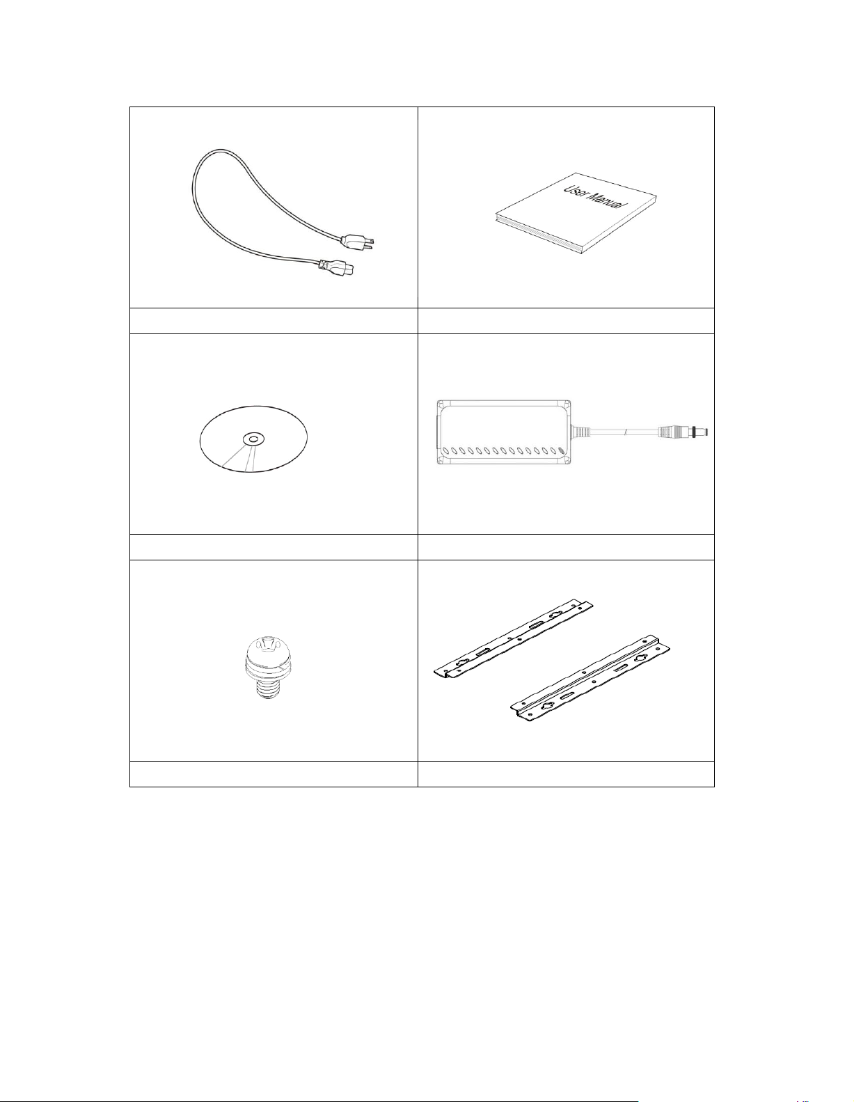
Accessories
a. Power Cord x 1
b. M/B Manual x 1
c. Driver CD x 1
d. Power Brick x 1
e. Mounting Rail Screw x 6
f. Mounting Rail x 2
Page 6

Components
Front V iew
Refer to the diagram below to identify the components on this side of the system.
PWR
The power LED illuminated when system been power on.
HDD
The hard disk LED blinks when data is being written into or read from the hard
disk drive.
RST
The reset switch allows reset the system.
ON/OFF
The power switch allows powering O N and OFF the system.
USB
The USB (Universal Serial Bus) port is compatible with USB devices such as
keyboards, mouse devices, cameras, and hard disk drives. USB allows many
devices to run simultaneously on a single computer, with some peripheral acting
as additional plug-in sites or hubs.
Page 7
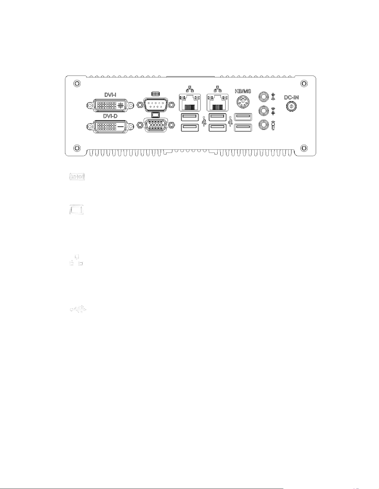
Rear Vie w
Refer to the diagram below to identify the components on this side of the system.
CO M1, Communication or serial port one is compatible with RS-232 interface.
Video Graphic Array (VGA) port supports a VGA-compatible device such as a
monitor or projector. The system default display output port.
The eight-pin RJ-45 LAN port supports a standard Ethernet cable for connection
to a local network.
The USB (Universal Serial Bus) port is compatible with USB devices such as
keyboards, mouse devices, cameras, and hard disk drives. USB allows many
devices to run simultaneously on a single computer, with some peripheral acting
as additional plug-in sites or hubs.
KB / MS
The PS/2 keyboard port is use to connect PS/2 compatible devices such as
keyboard, MSR and scanner. The PS/2 mouse port is use to connect PS/2
mouse.
Page 8

DVI-D / DVI-I
The Digital Visual Interface (DVI) port supports a high quality VGA-compatible
device such as a monitor or projector to allow viewing on a larger external
display.
DVI-D only contain digital TMDS signal without analog VGA compatible single in
it.
The stereo headphone jack (3. 5mm) is used to connect the audio signal into
system to record or bypass it to storage or LINE OUT.
The stereo audio jack (3.5mm) is used to connect the system’s audio out signal to
amplified speakers or headphones.
The microphone jack is designed to connect the microphone used for video
conferencing, voice narrations, or simple audio recordings.
DC IN
The supplied power adapter converts AC power to DC power for use with this
jack. Power supplied through this jack supplies power to the system. To prevent
damage to the system, always use the supplied power adapter.
Page 9

Specification
Construction
Alu minum
Chassis C olor
Silver
Storage
2.5” 80GB SATA HDD x 1
Mounting
Desktop or wall mount
Dimensions
199(W) x 63. 4(H) x 232( D)mm
(7.83” x 2.50” x 9.13” )
Power Supply
80W DC adapter
Operating
Temperature
0°C ~ 45°C (32 °F ~ 113°F)
Storage
Temperature
-20°C ~ 80°C
Relativ e H umidity
5~95% @45°C (non -con densing)
Vibration
HDD: 0.25g/5 ~500Hz random operation
Shock
HDD: 15g peak acceleration (11 msec d uration)
RoHS
Available
?This specification is subject to change without prior notice.
Page 10
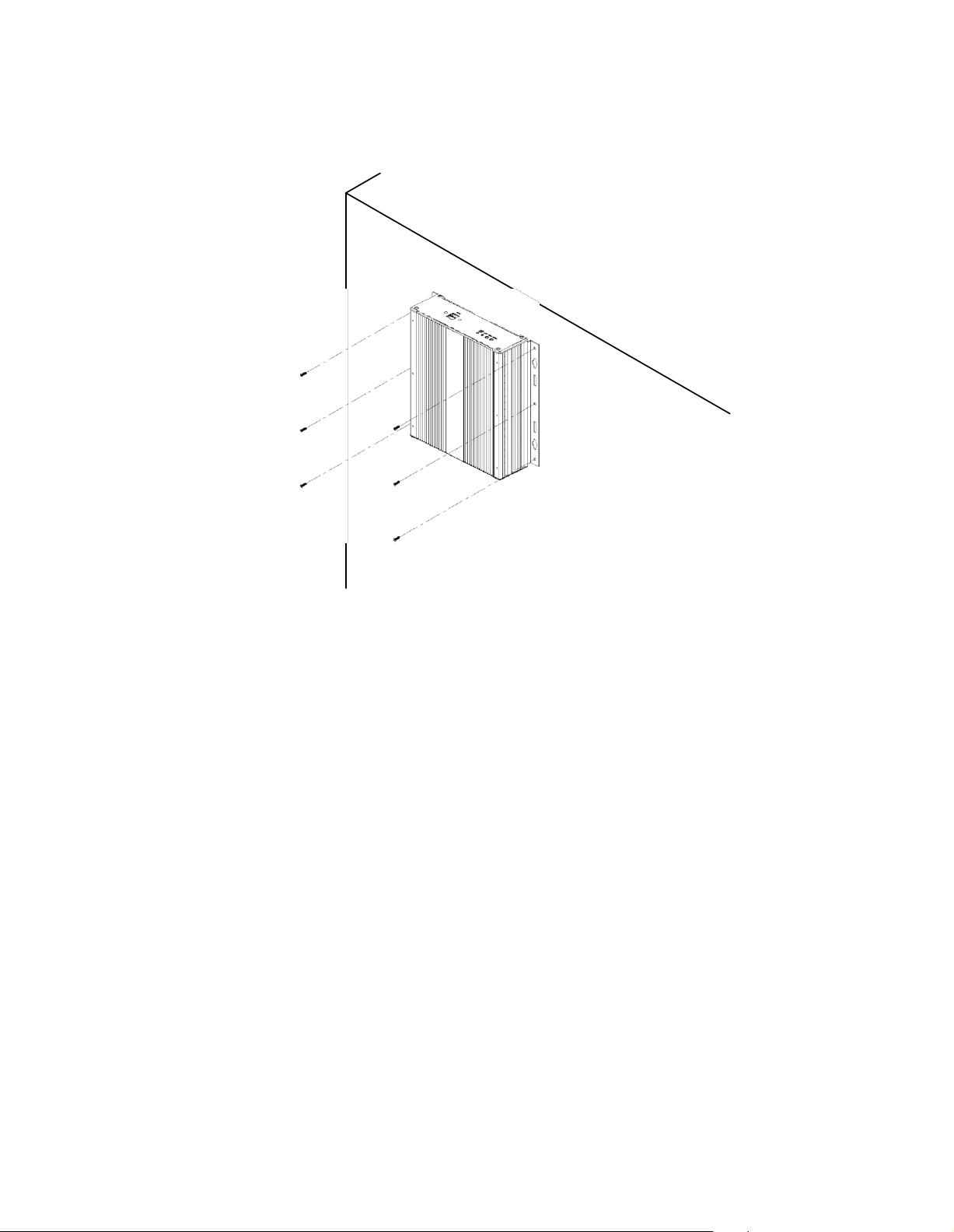
Mounting FES2953 to the Wall
Using attached mounting rail, you can install FES2953 on wood, drywall surface over
studs, or a solid concrete or metal plane. Ensure the installer uses at least four M4
length 8mm screws to secure the system on wall. Six M4 length 8mm screws are
recommended to secure the system on wall.
Fasteners are not included with the unit, and must be supplied by the installer. The
types of fasteners required are dependent on the type of wall construction. Choose
fasteners that are rated either ”Medium Duty“ or ”Heavy Duty.“ To assure proper
fastener selection and installation, follow the fastener manufacturer’s
recommendations.
Wa ll m ounting re quirem ents
Note: Before mounting the system on wall, ensure that you are following all
applicable building and electric codes.
When mounting, ensure that you have enough room for power and signal cable
Page 11

routing. And have good ventilation for power adapter. The method of mounting must
be able to support weight of the FES2953 plus the suspend weight of all the cables
to be attached to the system. Use the following methods for mounting your system:
Mounting to hollow w alls
Method 1: Wood surface – A minimum wood thickness – 38mm (1.5in.) by
25.4 cm (10in.) – of high, construction – grade wood is recommended.
Note: This method provides the most reliable attachment of the unit with
little risk that the unit will come loose or require ongoing maintenance.
Method 2: Drywall w alls - Drywall over wood studs is acceptable.
Mounting to a solid concrete or brick wall - Mounts on a flat smooth surface.
Sele cting the location
Plan the mounting location thoroughly. Locations such as walkway areas, hallways,
and crowded areas are not recommended. Mount the unit to a flat, sturdy,
structurally sound column or wall surface.
The best mounting surface is a standard countertop, cabinet, table, or other
structure that is minimally the width and length of the unit. This recommendation
reduces the risk that someone may accidentally walk into and damage the device.
Local laws governing the safety of individuals might require this type of
consideration.
Page 12
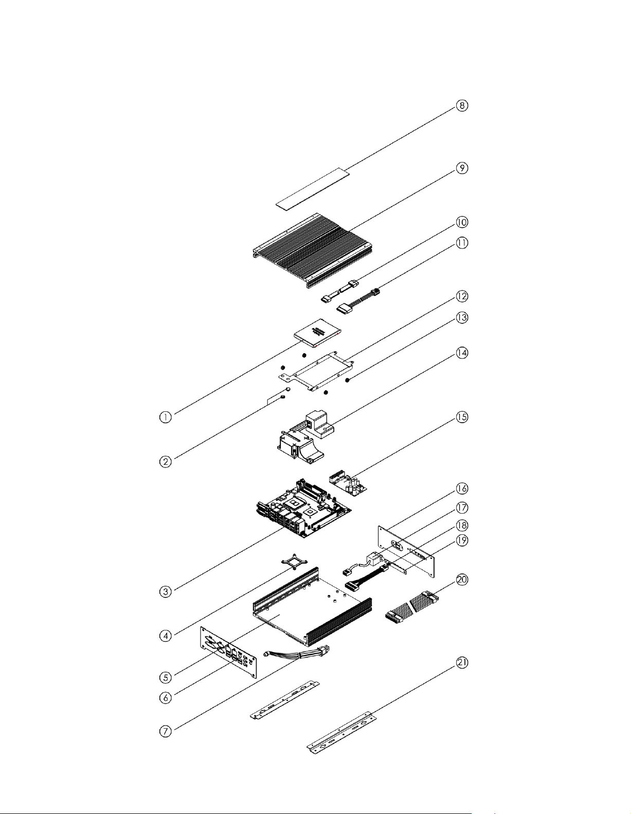
Exploded view of the FES2953 assembly
Page 13

Parts description
Part NO.
Description
Part NO.
Description
1
HDD
2
HDD bracket rubber foot
3
System mainboard
4
CPU heatsink bracket
5
Bottom chassis
6
Rear panel
7
DC extension cable
8
Name panel
9
Top chassis
10
SATA signal cable
11
SATA power cable
12
HDD bracket
13
Anti-Vibrate grommet
14
Heat pipe
15
I D450
16
Front panel
17
USB extension cable
18
Control panel cable
19
IB881-SW Board
20
ATX power extension cable
21
Mounting rail
Page 14

D RI
V ERS INSTALLATION
D rivers Ins tallation
T hi s secti on de sc ri bes t he
drivers under the W indows 2000 a nd W indows X P . The soft ware a nd
drivers a re i nc luded with the motherboard. If you find the ite ms missing,
ple ase c ont act the vendor w here you made the purchase. The contents of
instal
lati on proce dures for software a nd
thi s secti on include t he
Chipset S oft ware Insta llat ion Uti lit
V GA Drive rs Inst alla tion
Real tek H D A udi o Driver
LA N D rivers Insta llat ion
M anagement E ngine
IMPOR
A fter
TAN T N OTE:
instal
ling your W indows
you must inst all fi rst t he Intel Chipset
follow
ing:
y......................................... ...........
....................................................................
Instal
lati
on.................................................
.....................................................................
Interfac e ............................................................
operati
ng syste m (Windows 2000/ X P),
Softw
are Inst alla tion U tili ty
before proce eding wit h t he drivers insta lla tion.
13
15
17
18
20
Page 15
D R
IV
ER
SINSTALLA
TION
Ch ip set S oftware
The Chipset D ri vers should be
drivers t o e na ble P lug & P lay INF support for c hi pset c
Fol low t he
instructio
ns below to
Installa
install
ed first before the soft wa re
comple
tio n Utility
te t he inst alla tion.
ompone
nt s.
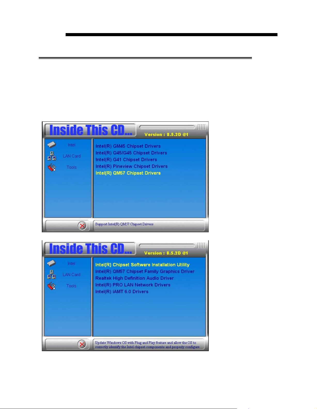
1. Insert the CD t ha t comes w ith the board. Cl ick In tel a nd t he n Int el(R)
QM 57 Chipset D ri vers.
2. Click Inte l(R) Ch ipset S oftware In sta llatio n U tili ty.
3. W he n t he W elcome screen to the Intel®
appea
rs, cli ck Next to continu e.
Chipse t Devi
ce
Softw
are
Page 16

DRIVE
RSINST
ALLATION
4. Click Yes to accept the software license agreement and proceed with
the installation process.
5. On the Readme File Information screen, click Next to continue the
installation.
6. The Setup process is now complete. Click Finish to restart the
computer and for changes to take effect.
Page 17

D R
IV
E R S
IN
S TA L L A
TI
ON
V G A D r iv ers I
N O T E: B
efo
re in
nst
al la ti on
sta
ll ing th e I nt
el(R
D riv er, th e M ic ro so ft .N ET F ra me
in
sta
l led.
T o in s tal l th e V GA dri ve rs, fo ll o w th e s
1 .
Ins
ert th e C D t ha t co m es w ith th e b o
Q M 5 7 C
2 . C lick I nt
hip
s et D r
el(R
) QM 5 7 C
iver
s .
hip
s et F a m i ly G ra p hi cs D r
) Q M 5 7 C hi p set F a m i ly Gr a p hic s
wo
rk 3 .5
tep
ard
SP
I sh o ul d b e fir st
s b
elo
w .
. Cl ick I nte l an d t h en I nt
iver
.
el(R
)
3 . W h en th e W elco me scre en ap p
ears
, cli ck
Nex
t to co n
tin
u e.
Page 18

D R I V E R S I N S T A L L A T I O N
4 . C l ic k Y e s t o to a g r e e w i th t he li c e n s e a g r e e m e n t a n d c o n tin u e th e
in s ta l la ti o n .
5 . O n t h e R e a d m e F ile In f o r m a t io n
sc
r e e n , c lic k N e x t t o c o n tin u e t h e
in s ta l la ti o n of t he I n te l® G r a p h ic s M e d ia A c c e le r a t o r D r iv e r .
6 . O n S e tu p P r o
gr
e ss
sc
r e e n , c li c k N e x t to c o n ti n u e .
7 . S e tu p c o m p le te . C lic k F i n is h t o r e sta r t th e c o m p u te r a n d fo r c h a n g e s
to t a k e e f f e c t .
Page 19

DRIVERSINSTALLATION
Realtek HD Audio Driver Installation
Follow the steps below to install the Realtek HD Audio Drivers.
1. Insert the CD that comes with the board. Click Intel and then Intel(R)
QM57 Chipset Drivers.
2. Click Realtek High Definition Audio Driver.
3. On the W elco me to the InstallShield Wizard screen, click Next.
3. InstallShield W izard is complete. Click Finish to restart the computer.
Page 20

D RI
V E RS INST
ALLAT ION
LAN
Fol low th e s teps be low to in stal l the In te l LAN dr
Driver s Installa
tion
ivers
.
1. Insert t he CD t hat comes wit h the board. Clic k I nte l and t hen I n tel(R)
Q M57 Chi pset Dr
iver
s .
2. Clic k I nt el(R) PRO L AN N etwork D ri ver.
3. When the We lcome s creen
cl ick Ye s to to a gre e wi th the l
appea
rs, cli ck Next. O n t he ne xt scre en,
icens e agree
me nt.
Page 21

DRIVERSINSTALLATION
4. Click the chec kbox for Drivers in the Setup Options screen to select
it
and click Next to continue.
5. The wizard is rea dy to begin installation. Click Install to begin the
installation.
Page 22

6. W hen Ins tal lS hi eld W i zard is
complet
D RI
V E RS INST
e, clic k F i ni sh .
ALLAT ION
Page 23

DR
IV
E R S
IN
S TALL ATI ON
Ma nage me
nt E ngine
Int erf
ac e
N O T E: B efo r e ins ta lli ng th e I nte l(R ) A M T 6 .0 Dr ive rs , the
M ic ro so ft .N ET Fr a mew o rk 3 .5 SPI sh o uld be firs t ins ta lle d.
Fo ll o w th e ste ps
1 . In sert th e d riv e rs d is c th at co m es wit h th e m o th erb o ard . C li ck In tel
an d th en I nt el(R ) A MT 6 .0 D ri ver s.
belo
w to in sta ll the I ntel M a na g e men t E ng in e.
Page 24

D RI
V ERS INST
ALLATION
2. W hen the Wel come scree n to t he Install Shiel d Wi zard for Inte l®
M
anageme
nt Engi ne Components, c lick Next. On the ne xt scree n, cli ck
Ye s to t o a gree with the l icense agree me nt.
2. W he n the Setup Progress screen a ppe ars, clic k Next. T hen, cli ck
Finish when the setup progress has be en suc
cessfull
y i nst alle d.
Page 25

D R
IV
ER SINSTALLA TION
Page 26

BI OS SETUP
BIOS Setup
T hi s c ha pter describes the different set tings avail able i n the BIOS that
co me s with t he board. The t opics covered i n this chapter are as
follo ws:
BIOS
BIOS Setup
Introductio
....................................................................................................
n ........................................................................................ 25
2 5
Main BIOS Se tup .........................................................................................26
Adva nc ed Se tti ngs ........................................................................................ 27
Chipset Setti ng s
............ ......................................................................... .......
3 8
Boot Setti ngs ................................................................................................. 42
Securit
y Sett ings
...........................................................................................
43
Save & Exi t Se tti ngs .................................................................................... 44
Page 27

B IO
S S E T U P
B I O S I n tr o d u c ti o n
T h e B I O S (Ba si c I n p u t/O u tp u t S y s
s
y ste m ’ s R O M su p p o r ts I n
lo w -
le
v e l s u p po r t f o r a s
te
l p ro c e ss o r s. T h e B I O S
ta
n d a r d d e v
a n d p a r a lle l p o r ts . I t a ls o p a s sw o r d p r o
f
o r d e
ta i le
d f in e - tu n in g o f th e c hi p
te
ic
se
t c o n tr o
m ) in s
e s u c h a s d is k d r i ve s, s e r
te
c tio n a s w e ll a s s p e c i a l su p p o r
ta
llin
g th e e n
ll e d i n y o u r c o m pu t e
pr
o v id e s c r itic a l
ia
l p o r ts
tir
e s y ste m .
B I O S S e tu p
T h e B I O S p r ov i de s a S e tu p u ti lit y p r o g r a m f o r s p e c i f yi n g th e s y ste m
c o n f ig u r a ti on s a n d
S e tu p u t ilit y. W h e n y o u tu r n o n th e c o m p u
a c tiv a te d. P r e ss in g th e < D e l> k e y im m e d i a
S e tu p u ti lit y. If yo u a r e a li ttle b it
se
t tin g s. T h e
BI
O S R O M o f t h e s ys
te
r , th e B IO S is i m m e d
te
l y a llo w s yo u to e n
la
te p r e s si ng th e < D e l> k e y , P O S T
te
m s to r e s th e
te
ia
te ly
r t h e
(P o w e r O n S e lf T e st ) w ill c o n tin u e w ith i ts t e st r o ut in e s , th u s p r e ve nt in g
y o u f r o m i nv o k in g th e S e t up . I f y o u s till w is h to e n
s ys te m b y p r e s si ng th e ” Re
< Ct r l> , < A lt > a n d < D e
se
t ” b u tt o n o r s im u lta ne o u sly p r e ss in g t h e
le
te > k e y s. Y o u c a n a l so r e st a r t b y tu r n in g t he
s y ste m O f f a nd b a c k O n a ga in . T h e fo l lo w i n g m e s
te
r S e t up , r e st a r t th e
sa
g e w il l a p p e a r o n
th e s c r e e n:
Press <DEL> to Enter Set
u p
I n g e n e r a l, yo u p r e s s t he a r r o w k e y s to h ig h lig h t it e m s, < E n te r > t o
s e
le
c t, th e < P g U p > a n d < P g D n > k e ys to c h a n g e e nt r
ie
s , <F 1 > f o r h e lp
a n d < E sc > to q u i t.
W h e n y o u e n te r th e S e tu p u til ity , th e M a in M e n u sc r e e n w i ll a p p e a r o n
th e s c r e e n. T h e M a i n M e n u a ll o w s yo u t o s e le c t f r o m v a r io u s
se
t up
f u n c tio n s a n d e x it c ho i c e s .
r
t
Page 28

M a i n B I O S S e tu p
T h is se tu p allo ws
y o ur c o mp ut er s ys te m a nd s et t he s ys tem c lo
M a in A d v a n c e d C h ip s e t B o o t Se c u rit y S a v e & Ex it
B IO S IN F O R M A T IO N
M e m o ry In fo rm a tio n
T o tal M e m o ry 4 0 9 6 M B (D D R 3 10 6 6 )
S ys te m L a n gu a g e [En g l is h ]
S ys te m D a te [T u e 0 1 /0 6 /2 0 0 9 ]
S ys te m T i me [0 0 :0 8 :2 1 ]
A cc e ss L e ve l A d m in i str a to r
No t e: If th e s ys tem c a n n ot b
ch
th e C M OS s
yo
u t o re cord so m e b as ic ha rd ware c
a n g es w it h S
etti
Ap tio S e tu p U t ilit y
oo
t a fter ma ki ng a n d s av in g sy ste m
etu
p , th e A M I B
n g s th a t
res
et s
ck
.
→ ←
Select Scr e e n
↑↓
Select Item
E nt e r : S e l e c t
+ - C h a n g e F i e l d
F 1: G e n e r al H e l p
F 2: P r e v i ou s V a l u e s
F 3: O p t i m i z e d
F 4: S a v e ESC: E x i t
IO
S s u p p o rts a n o
yo
u r sy ste m to i ts d e fa u lt.
W a r ni
ng
:
ch
ca
o n g ly r
a n g es t o th e chip s et d ef a ul ts. T h ese d
re fu lly c h o sen b y b o th A M I a n d
to p ro vi d e th e a b s o lu te m a
rel ia b ili ty. C h a n g in g th e d
b
eco
me u n
sta
eco
b le
m m
en
d ed t h at
xim
efa
u lt s
an
d c ra s h i n s o me
yo
u a
vo
id ma k in g a n y
efa
yo
u r s ys tem ma n u fa ct u rer
u m p erf o rm a n ce a n d
co
u ld c
au
ca
se s.
It is
str
S ys tem L a n g u a g e
C ho ose the sy stem d ef au lt la ng ua ge .
S ys tem D a te
S e t th e D ate . U se T ab to
switc
h be tw ee n D ata ele m e nts.
S ys tem T im e
S e t th e
Tim
e . U se Ta b to sw itc h b etw e en D a ta e lem en ts.
B IO S S E T U P
on
f i
gu
rat io n s in
Default
ver rid
e to
u lts h a ve b ee n
s e th e
sys
tem to
Page 29

BIOS SETUP
Advanced Settings
This section allows you to configure and improve your system and
allows you to set up some system features according to your preference.
Main Advanced Chip set Bo ot Security Save & Exit
Legacy OpROM Support
Launch PXE OpROM
Launch Storage OpR OM
► PCI Subsystem Settings
► ACPI Settings
► W ake up event setting
► CPU Configuration
► SATA Configuration
► Intel IGD SWSCI OpRegion
► USB Configuration
► Super IO Configur ation
► H/W Monitor
► AMT Configur ation
► Ser ial Por t Console Redir ection
Launch PXE OpROM
Enable or Disable Boot Option for Legacy Network Devices.
Launch Storage OpROM
Enable or Disable Boot Option for Legacy Mass Storage Devices with Option
ROM.
► Wake up event setting
Enable/Disable Wake up event.
► Intelligent Power Sharing
Intelligent Power Sharing configuration menu.
NOTE: DTS must be enabled for Power Sharing to function.
► MXM 3.0/Hybrid Graphics
Enable/Disable the MXM 3.0 support..
Aptio Set up Ut
ility
→ ←
Select Screen
↑↓
Select Item
Enter: Select
+- Change Field
F1: General Help
F2: Previous Values
F3: Optimized Default
F4: Save ESC: Exit
Page 30

BIO
S
SETUP
PCI Subsystem Settings
This section allo ws you to configure the PCI, PCI-X and PCI Express
settings.
Main Advanced Chipset Bo ot Secu rit y Save & Exit
PCI Bus Dr iv er Vers ion V 2.02.01
PCI RO M Pri ority EF I Compatible RO M
PCI Common Settings
PCI Latency Timer 32 PCI Bus C loc ks
Ap tio Setu p Ut ilit y
→ ←
Select Screen
↑↓
Select Item
Enter: Select
+- Change Field
F1: General Help
F2: Previous Values
F3: Optimized Default
F4: Save ESC: Exit
PCI ROM Priority
In case of multiple Option ROMs (Legacy and EFI Compatible), specifies what
PCI Option ROM to launch.
PCI Latency Timer
Value to be programmed into PCI Latency Ti mer R egister.
Page 31

E n a bl e H i b e rn a tio n En a b l e d
A C PI S l e e p
Sta
te S 3 (S u s p e n d to R … )
→ ←
S e l e c t Screen
↑↓
S e l e c t Item
Enter: Select
+ - Change Field
F1: General Help
F2: Pr e v i o u s Va l u e s
F3: Optimized Def a u l t
F4: Save ESC: Exit
ACP
I S ettin gs
En abl e H ibe rn ati on
En ab les o r D isa ble s S
optio n m ay b e n ot ef fe c tive w ith
yste
ACP
I S le ep Sta te
S ele c t the high e st
butto n is p re sse d.
AC
P I sle e p sta te the
BI O S S E T U P
A ptio Se t up U t ility
m a bility to Hib er na te (O S /S4 S lee p S ta te). Th is
som
e O S .
syste
m w ill e nte r, w he n the S U S P EN D
Page 32

B IO
S S E T UP
Wa ke up ev ent s e ttings
Apt io S etup Utility
M ain Ad van ced Chipset Bo ot Secu rit y S av e & Exit
W ak e sy stem wi th Fi xed Ti m e Di
W ak e up hour 0
W ak e up mi nute 0
W ak e up sec ond 0
sabl
ed
→ ←
Select Sc reen
↑↓
Select Item
Enter: Sel e ct
+- Change F i eld
W ak e on Ring E nabled
W ak e on PM E E nabled
F1: Gen e ral Help
F2: Pre v ious
F3: O p tim ized
F4: Save ESC:
Val u e s
Def a ult
Exit
Wa ke sy ste m wi th Fix ed Ti me
En ab les or D isab les System wake o n alarm ev ent. When en ab led , System w ill
wake on th e hr ::mi n:: sec specified.
Wa ke on Ring
Th e op tions are Disabled and E nabled.
Wa ke on PM E
Th e op tions are Disabled and E nabled.
Page 33

A d ja c e n t C a c h e L i n e P r e f et c h
E n a b l e d
+ - Ch a n g e F i e l d
I n t e l V i rt u a li z at i o n T e c h n ol o g y
D i s a b l e d
F 1 : Ge n e r a l H e l p
P o w er T e c h n o lo g y
E n e r g y E f f ic i en t
F 2 : Pr e v i o u s V a l u e s
T D C L i m it
0
F 3 : O p t i m i z e d D e f a u l t
C P U C o n f ig u r a t i o n
T h i s s e c t i o n s h o w s t h e C P U c o n fi g u r a t i o n p a r a m e t e r s .
A p t i o S e tu p U ti l i t y
M a i n
C P U C o n f ig u r a t io n
P ro c e s s or T y p e I n t e l (R ) C o re ( T M ) i 5 C P U
E M T 6 4 S u p p o rt e d
P ro c e s s or S pe e d 2 3 9 4 M H z
P ro c e s s or S t ep p i n g 2 0 6 5 2
M ic ro c o d e R e v i s i o n 9
P ro c e s s or C o re s 2
I n t e l H T T e c h n ol o g y S u p p o rt e d
A d v a n c e d
C h i p s e t B o o t S e c u r i ty S a ve & E x i t
H y p er -t h re a d i n g E n a b l e d
A c t i v e P ro c e s s o r C o re s A l l
L i m i t C P U I D M a x i m u m D i s a b l e d
H a rd w a r e P r ef e t c h e r E n a b l e d
→ ←
↑↓
E n t e r : S e l e c t
S e l e c t S c r e e n
S e l e c t I t e m
B I O S S E T U P
T D P L i m i t 0
F 4 : S a v e E S C : Ex i t
H y p e r - t h r e a d in g
E n a b l e d fo r W i n d o w s X P a n d L i n u x (O S o p t i m i z e d fo r H y p e r -T h r e a d i n g
T e c h n o l o g y ) a n d D is a b l e d f o r o t h e r O S (O S n o t o p t im i z e d fo r H y p e r -T h r e a d i n g
T e c h n o l o g y ). W h e n D i s a b l e d , o n l y o n e t h re a d p e r e n a b l e d c o re i s e n a b l e d .
A c t i v e P r o c e s s o r C o r e s
N u m b e r o f c o r e s t o e n a b l e i n e a c h p r o c e s s o r p a c k a g e .
L im it C P U ID M a x i m u m
D i s a b l e d fo r W i n d o w s X P .
H a r d w a r e P r e f e t c h e r
T o t u r n o n / o ff t h e M L C s t re a m e r p r e fe t c h e r .
Page 34

B IO S S E T U P
Adj
ac en t Ca ch e L ine P re fe tc h
To tu rn o
Inte
W he n en ab led , a V M M c an
by V a nde r poo l T ec hn olog y.
P ow er Te ch
l V i
n/of
f pr ef etc hin g of a dja c en t c a ch e line s.
rtua liz
a tion
nolog
Tec
y
hno logy
utiliz
e the a dd itio na l ha r dw ar e c ap ab ilities pr ovid ed
En ab le the pow e r m a na ge m e nt fe a tur es.
TD C L
Tu rb o-X E M od e P roc e ssor TD C L im it in 1 /8 A gra nu lar ity. 0 m ea n s usin g the
fa c tor y-c on fig ure d va lue .
S AT A C
S AT A D e
im
i t / TD P Lim it
onfigu
vice
ra tion
s C o nfigu ra tion .
Ap tio S e tu p U t ilit y
M a in Ad v a n c e d C hips e t B o ot Se c u rit y S a v e & Ex it
S A TA C o n fig u r a ti o n
S A TA Po r t0 H i ta c hi H D S 7 2 1 (1 6 0 .0 GB )
S A TA Po r t1 N o t P re s e n t
S A TA Po r t2 N o t P re s e n t
S A TA Po r t3 N o t P re s e n t
→ ←
Select S c r e e n
↑↓
Select It em
E nter: Select
+ - Change Field
S A TA Po r t4 N o t P re se n t
S A TA Po r t5 A TA PI i H D S 1 1 AT AP I
S A TA M od e ID E Mo d e
S e ri a l- AT A C o n tr o ll e r 0 C o m p a tib l e d
S e ri a l- AT A C o n tr o ll e r 1 E nh a n c e d
F 1: General Help
F 2: Previou s V a l u e s
F 3: Optimized D e f a u l t
F 4: Save ESC: Exit
S AT A M od e
(1 ) I DE M ode .
(2 ) A
HC
I M od e.
(3 ) R A ID M od e.
S er ia
En ab le / Dis ab le S er ia l A TA C
l-AT
A C
ontr
oll er
ontr
olle r.
Page 35

In te l IG D S W S C I O p Re g io n
A pt io S e tup U tilit y
M a in A d v a n c e d C h
In te l IG D SW SC I Op R e g io n C o n fi g u ra ti on
D V MT /FIX E D Me mo r y 2 5 6 M B
IGD – B o o t Ty p e V B IOS D e fa u l
A cti ve L FP N o L V D S P an e l
C o l or D e p th 1 8 B i t
L FP L C D P a n e l T yp e 1 0 2 4 x 7 6 8 LV D S
P a n el S ca l in g A u to
ips
e t B oo t Se c ur ity S a ve & Ex it
DV M T /F IX ED M e m o r y
S
ele
c t D V M T /F IX ED M od e M em or y siz e u sed by I
Op tions a re 128 M B , 2 56M B an d M a
xim
u m .
IG D –
S
ele
if ex ter na l gr ap
EF
Bo
o t T
yp
e
c t the V id eo D ev ice w
hic
s pr
ese
P an d C R
T+ E FP
.
hic
h wi ll be ac
tiva
nt. Op tio ns a re V B IO S
Acti
ve L F P
S
ele
c t th e A ctive
LF
P C on figu ra tion .
No L VD S : VB IO S d oe s n ot en ab le LV D S .
In
t-LV
D S : V B I OS en ab le s L VD S driv er by In teg ra ted en co de r.
S DV O L VD S : V B I OS e na
eD P : LV DS D
rive
n b y I nt- D is
ble
s L V DS dr
pla
yP or t e n cod er .
ive
Pa n e l S c ali n g
S
ele
c t th e
Op tions a re
LC
D pa ne l s ca ling op tion us ed by th e I
Auto
, F or c e S c alin g, O ff a nd M a
t
ted d ur ing P
→ ←
Select Screen
↑↓
Select Item
Enter: Select
+ - Change Field
F1: General Help
F2: Previous Values
F3: Optimized D efault
F4: Save ESC: Exit
nte
rn al G ra ph ics
OS
De
fa ult, C R T,
r by S D V O e nc
nte
rn al Gr a
inta
in Asp ec t R atio .
B I O S S E T U P
De vic
e.
T . Th is ha s no e ff ec t
LF
ode
P , C R
r .
phic
s
De vic
T+
L F P,
e.
Page 36

US B Devi ces :
2 Hubs
Legac y US B S upport Enabl ed
E HCI Hand-off E nabled
Dev ic e Reset T im eout 20 s ec
→ ←
Select Screen
↑↓
Select I tem
Enter: Select
+- Change Field
F1: General Help
F2: Previous Values
F3: Optimized Default
F4: Save ESC: Exit
USB Co nfiguration
Apt io S etup Utility
B IO
S SETUP
Legacy U SB Su pport
En ab les L eg acy USB supp ort.
AUT O op tion disables legacy su ppo rt if no USB devices are co nnected .
DISABLE o ption will k eep USB d ev ices av ailable only for E FI app lications .
EHC
En ab led /Dis abled. Th is is a workaro und for Oses witho ut EHCI h an d-o ff
sup port. T he E HC I ownersh ip ch an ge sh ould b e claimed b y EHCI d river.
I H an d-off
Devi
USB mass storage d ev ice Start Un it com man d timeout.
Options are: 10 sec / 20 s ec / 3 0 sec / 4 0 sec.
ce R eset T imeout
Page 37

BIOS SETUP
Super IO Configuration
Main Advanced Ch ipset Boo t Security Save & Exit
Super IO Configuration
Super IO Chip F intek F81865
-> Serial Por t 0 C onfiguration
-> Serial Por t 1 C onfiguration
-> Serial Por t 2 C onfiguration
-> Serial Por t 3 C onfiguration
Power Failur e Alway s off
Power ON F unction Disabled
ACPI Shutdown Temperatur e Disabled
Aptio Set up Ut ility
→ ←
Select Screen
↑↓
Select Item
Enter: Select
+- Change Field
F1: General Help
F2: Previous Values
F3: Optimized Default
F4: Save ESC: Exit
Serial Port Configuration
Set Paramet ers of Serial Ports. User can Enable/Disable the serial port and
Select an optimal settings for the Super IO Device.
Power Failure
Options are:
Keep last state
Bypass mode
Always on
Always off (default)
Page 38

H/W Monitor
Apt io Setup Utilit y
BIOS SETUP
Main Advance d
PC Health Status
System Temperatur e1 + 51 C
System Temperatur e 2 + 35 C
System FAN1 Speed N /A
System FAN2 Speed 7109 RPM
VCC3V + 3.408 V
Vin0 + 0.928 V
Vin2 + 5.087 V
Vin3 + 12.232 V
VSB3V + 3.424 V
VBAT + 3.184 V
Fan1 Smart F an Control 50 C
Fan2 Smart F an Control D isabled
Chipset Boo t
Secu rit y Save & Exit
→ ←
Select Screen
↑↓
Select Item
Enter: Select
+- Change Field
F1: General Help
F2: Previous Values
F3: Optimized Default
F4: Save ESC: Exit
Temperatures/Voltages
These fields are the parameters of the hardware monitoring function
feature of the motherboard. The values are read-only values as
monitored by the system and show the PC health status.
Fan1/Fan2 Smart Fan Control
This field enables or disables the smart fan feature. At a certain
temperature, the fan starts turning. Once the temperature drops to a
certain level, it stops turning again.
Page 39

M ain Ad va n ced Chip set Bo ot S ecur ity Save & E xit
A MT E nabled
→ ←
Select Screen
↑↓
Select Item
Enter: S el ect
+- Change Fie ld
F1: G en era l Help
F2: P re vio us Value s
F3: O pt imi zed D efa ult
F4: Save ESC: Exit
AMT C onfi guration
Apt io S etup Utilit
y
AMT
Op tions are Enabled and
Disabled
.
Se rial Port Con sol e R ed irec tion
Main Ad van ce d Chipset Bo ot S ecur ity Save & E xit
CO M 0 (Di sabl ed)
Cons ole Redi rec tion P ort i s Di sabl ed
S eri al Port f or Out- of-B and Managem ent/
W indows E m ergenc y M anagement S erv i ces (EM S )
Cons ole Redi rec tion E nabled
O ut-of- Band M gm t Por t CO M0 (Di sabl ed)
Data B i ts 8
P ari ty None
S top B its 1
T erm inal Ty pe V T- UTF8
Apt io S etup Utilit y
Con sol e R ed ire c tion
Cons
ole Redirection E
nable/Dis
ab le.
Termi
VT -UTF8 is th e p referred
best cho ice is VT 100 + and th en VT 100.
nal Typ e
termin
al ty pe for ou
t-of-b
→ ←
Select Screen
↑↓
Select Item
Enter: S el ect
+- Change Fie ld
F1: G en era l Help
F2: P re vio us Value s
F3: O pt imi zed D efa ult
F4: Save ESC: Exit
an d management. Th e n ex t
BI OS SETUP
Page 40

Main Ad van ced Ch ipset Bo ot Secu rit y S ave & Exit
? Nor th Br idge
? S outh Br idge
? ME Subs ys tem
→ ←
Select Screen
↑↓
Select Item
Enter: Select
+- Change Field
F1: G eneral Help
F2: P revious Values
F3: Optimi zed Default
F4: Save ESC: Exit
C hipset Settings
T hi s sec tion a llows you to c onfi gure and i mprove your system
BI OS
al lows you to set up some syst em feat ure s acc ording t o your
Aptio Set up Ut ility
North Bridg e
This item sh ows th e North Brid ge Parameters.
South Bridg e
This item sh ows th e Sou th Brid ge Parameters.
ME Subsystem
This item sh ows th e ME Subsy stem Param eters.
preference .
SETUP
and
Page 41

M e mo r y In fo r ma ti o n
C P U Ty p e A r ra n d a le
To ta l M e mo r y 4 0 9 6 M B (D D R 3 1 0 6 6 )
M e mo r y S l o t0 2 0 4 8 M B (D D R 3 1 0 6 6 )
M e mo r y S l o t1 0
M e mo r y S l o t2 2 0 4 8 M B (D D R 3 1 0 6 6 )
M e mo r y S l o t3 1 4 0
R A S# A cti v e Ti me (tR AS ) 2 0
R o w P re ch a r g e Ti me (tR P) 7
R A S# to C A S # D e la y (tR C D ) 7
R o w R e fre s h C yc l e Ti me a (tR FC ) 6 0
W ri te to R e a d D e la y (tW T R ) 4
A cti ve to A cti ve D el a y(tR R D ) 4
R e a d C A S# P re c h a rg e (tR TP ) 5
L o w M M IO A li g n 6 4 M
In i ti a te Gr a p hi c Ad a p te r P EG /IGD
Gr a p h ic s T u rb o IM ON C u r re n t 3 1
V T-d D i sa b l e d
P C I Ex p re s s P o rt A u to
IGD M e m o ry 3 2 M
P AV P M od e D i sa b l e d
P EG Fo r ce Ge n 1 D i sa b l e d
→ ←
Select Sc r een
↑↓
Select Item
Ent e r: Se l ect
+- Cha nge F i eld
F1: Gener a l Help
F2: Previ o us V a lue s
F3: O pti m ize d Defau l t
F4: S ave ESC: Exit
Nor th B ri dge
This sect ion allo ws you to configu re t he North B ridge C hips et.
A pt io S e tup U tilit y
BI O S S E T U P
Low M M IO A lign
Low MM IO re sou rc es a lign a t 6 4M
Initi ate Gr aphi c Ada pte r
Sele
c t w hic h gr ap hic s co ntro ller to use a s the
Op tions a re IG D,
PCI/I
GD , PC I/PE G, PE G/I GD , PE G/PC I an d SG.
Gra phi cs Tur bo IM ON Cur re nt
Gr ap hic s tu rb o IM ON cu rr e nt valu e s su ppo rte d (14 - 31).
VT -d
VT -d E na ble /D isab le.
B/102
4MB.
prima
r y boo t d e
vice
.
Page 42

BIOS SETUP
PCI Express Port
Options are Disabled, Enabled and Auto.
IGD Memory
IGD Share Memory Size. Options are Disable, 32M, 64M and 128M.
PAVP Mode
Select PAVP Mode usedby Internal Graphics Device. Options are Disabled and
Enabled.
PEG Force Gen1
PCI Express Port Force Gen1. Options are Disabled and
Page 43

B IOS SETU P
SB C hip set Co nfigu ration
This se ction al lows you t o confi gure the So ut h Bri dge Chipset .
M ain Ad vanced C h i p set Boo t S ecur ity S ave & E xit
SB Chi pset Confi guration
SM B us C ontr oll er E nabl ed
GbE Control ler E nabl ed
W ake on LA N from S 5 E nabl ed
SLP _S 4 As ser tion S tretc h Enabl e E nabl ed
SLP _S 4 As ser tion W i dth 4- 5 Sec onds
Audi o Configur ati on
Az ali a HD A udio E nabl ed
Ap tio S etu p Ut ility
Select Screen
→ ←
↑↓
Select Item
Enter: Sele ct
+- Change Field
F1: G eneral He lp
F2: P revious Values
F3: Optimized Default
F4: Save ESC: Exit
SMBus C ontroller
SMBu s Controller help.
GbE C ontroller
Th is is con stan tly en ab led .
Wake on LAN fro m S5
Wake o n LAN fro m S5 h elp .
Resto re AC Pow er L oss
Options are Power Off, Power On and L as t State.
SLP_S4 A ssertion Stretch En abl e
Select a min imum
assertio
n widt h of the
SLP_S4
# signal.
Aud io C onfi guratio n
Th e Aud io Configuration settings E nable/Disable the Azalia HD Aud io an d the
Azalia in ternal HDMI cod ec.
Page 44

In te rr u p t 1 9 C a n tur e
D is a b le d
B o o t Op ti o n Pr io r iti e s
B o o t Op ti o n # 1
S AT A: A TA P I
iH … )
H a r d D ri ve B BS P ri o ri tie s
B o o t Se tti n g s
T h is se
p
referen
ctio
n al lo ws y o u to co n fig u re th e b o o t s ett in g s ac co rd in g to y o ur
ce .
Ap tio S e tu p U t ilit y
M a in Ad v a nc e d C
B o o t C o n fig u r a ti o n
Q u ie t B o o t
F a st B o o t D i sa b l e d
S e tu p Pr o mp t T i me o u t 1
B o o tu p N u mL o c k S ta te O n
C S M 1 6 M o d ul e V e rs io n 0 7 .6 0
G a te A2 0 A cti ve U p o n R e q u e s t
hips
e t B o ot Se c u rit y S a v e & Ex it
Q ui et B oot
En ab les
/Disa ble
s Qu iet B oo t o ption.
Fa st B oot
En ab les
la
unc
S etup P rom pt T
N
um
65
Bo otup N um
S e le c t th e ke yb oa rd N um
G a
U P ON R EQ UE S T – G A20 ca n be
A
LW
c ode is e xe c
O pti on R O M M e ss
S e t d
Inte
En ab le: A llows O ptio n R OM s to tr a p In t 19 .
/Disa ble
h a ctiv e bo ot
s boo t w ith
option
. H as n o e f fe ct f or B B S bo ot
im
e out
initia
liz a tion of a m inim al se t o f de
be r o f se co nds to w ait f or se tup a c
535(0x
F F
FF
) m ea ns ind ef inite
Loc
k S ta te
Loc k sta
teA2
0 Ac tiv e
A YS – do n ot allo w
ute
d ab ove 1M B .
ispla
y m ode fo r Op tion R O M . Op tions a re Fo rc e B I O S a nd K e ep C u rr en t.
rr upt 19 Ca
ntur
disa
bling G A2 0; this op tion is
age
s
e
wa
iting.
te .
disa ble d usin
D i s a bl e d
tiva
tion ke y.
→ ←
↑↓
E nter: Sel e c t
+ - C h ange F i e l d
F 1: G e n er al He l p
F 2: P r e vi ous Val u e s
F 3: Opti m i z e d De f a u l t
F 4: Save E S C : E x i t
optio
g B IO S s er
use
B IO
S S E T U P
Select S creen
Select Item
vic
e s r e
quir
ns.
vic
es.
fu l w he n a ny R T
e d to
Page 45

BIOS SETUP
Boot Option Priorities
Sets the system boot order.
Hard Drive BBS Priorities
Set the order of the legacy devices in this group.
Security Settings
This section allows you to configure and improve your system and
allows you to set up some system features according to your preference.
Main Advanced Chipset Boot Security Save & Exit
Password Description
If ONLY the Administrator’s password is set, then
this only limits accesss to Setup and is only asked
for when entering Setup.
If ONLY the User’s password is set, then this is a
power on password and must be entered to boot
or enter Setup. In Setup the User will have
Administrator rights
Administrator Password
User Password
Administrator Password
Set Setup Administrator Password.
User Password
Set User Password.
Aptio Setup
Utility
→ ←
Select Screen
↑↓
Select Item
Enter: Select
+- Change Field
F1: General Help
F2: Previous Values
F3: Optimized Default
F4: Save ESC: Exit
Page 46

Save & Exit Set ting s
Ap tio S etu p Ut ilit y
M ain Ad van ced Chipset Bo ot Secu rit y S ave & Exit
S ave Changes and E xi t
Di s ac ard Changes and E xi t
S ave Changes and R es et
Di s card Changes and Res et
S ave Changes
Di s card Changes
Res tore
S ave as User Defaults
Res tore Us er
Defaul
ts
Defaul
ts
B oot Ov erri de
S A TA : AT AP I i HDS 116 4
S A TA : Hitac hi H
DS721616P
LA380
Launc h EF I Shel l fr om fi l esy stem devi ce
S ave O ptions
► Reset S ys tem wi th M E di s able M ode
Save C hanges and Exit
Exit syste m se tup after saving the c ha nge s.
Di sacard Ch ang es an d Exit
Exit syste m se tup wit hout saving any changes.
Save C hanges and Reset
Rese t the syst em after saving the c ha nge s.
Di scard C han ges and Reset
Rese t syste m setup w ithout saving any changes.
Save C hanges
Save Ch an ges d one so far to any o f the setu p op tio ns.
Di scard C han ges
Discard Changes don e so far to an y of th e setup o ption s.
Resto re Defau lts
Restore/Load Defau lts v alu es for all the setup o ption s.
B IO
→ ←
Select Screen
↑↓
Select Item
Enter: S elect
S SETUP
Page 47

Save as User Defaults
Save the chang es done so far as User Defaults.
Restore User Defaults
Restore the User Defaults to all the setup options.
Boot Override
Pressing ENTERcauses the system to enter the OS.
Launch EFI Shell fromfilesystem device
Attempts to Launch EFI Shell application (Shellx64.efi) from one of the
available filesystem devices.
Reset System with ME disable Mode
ME will run into the temporary disable mode.
BIOS SETUP
 Loading...