

Page 1

User Manual
FES2217: Fanless Embedded System Atom D525
Dual Core 1.86GHz Processor
FES2217
Fanless Embedded System
14628 Ce ntral Ave,
Chino , CA 91710
tel:909.597.7 588, fax:909.597.1939
© Copyright 2013 Acnodes, Inc.
All righ ts reserved. Product descripti on and product speci ficat ions
are subj ect to change w ith out n oti ce. F or lates t product inform ati on,
ple ase vis it Acnod es’ we b site at www.ac nodes.c om.
Page 2

Copyright
This publication c ontains information that is protected by copyright. No part of it may be reproduced in
any form or by any means or used to make any transformation/adaptation without the prior written
permission from the copyright holders. The manufacturer reserves the right to revise this publication and
make changes to its contents at any time, without obligation to notify any person or entity of such
revisions or changes.
©2013. All Rights Reserved.
Trademarks
All trademarks and registered trademarks of products appearing in this manual are the properties of their
respective holders.
Notice:
1. The changes or modifications n ot expressly approved by th e party responsible for compliance could void the user’s authority
to operate the eq uipment.
2. Shielded interface cables must be used in or der to comply with the emission limits.
Static Electricity Precautions
It is quite easy to inadvertently dam age the system board, components or devices even before installing
them in your system unit. Static electrical discharge can damage computer components wi thout causing
any signs of physical damage. You must take extra care in handling them to ensure against electrostatic
build up.
1. To prevent electrostatic build up, le ave the system board in its anti-static bag until you are ready to install
it.
2. Wear an antistatic wrist st rap.
3. Do all preparation work on a static-free surface.
4. Hold the device only by its edges. Be careful not to touch any of the components, contacts or
connections.
5. Avoid touching the pins or contacting all modules and connectors. Hold modules or connectors by their
ends.
Important:
Electrostatic discharge (ESD) can damage your p rocessor, disk drive and other components. Perform the upgrade instruction
procedures described at an ESD wor kstation only. If such a station is not available, you can provide some ESD protection by
wearing an antistatic wrist strap and attaching it to a metal part of the system chassis. If a wrist strap is unavailable, es tablish
and maintain contact with the system chassis throughout any procedures requiring ESD protection.
Page 3

FES2217
Safety Measures
To avoid damage to the system:
• Use the correct AC input voltage range to reduce the risk of electric shock.
• Unplug the power cord before removing the system chassis cover for installation or servicing. After
installation or servicing, cover the system chassis before plugging the power cord.
Battery:
• Danger of explosion if battery incorrectly replaced.
• Replace only w ith the same or equivalent type recommend by the manufacturer.
• Dispose o f used batteries according to local ordinance.
Warranty
1. Warranty does not cover damages or failures caused b y misuse of th e p roduct, inability to use the
product, unauthorized replacem ent or any kind of alterations of components an d product
specifications.
2. The warranty is voided if the product has been exposed to physical abuse, improper installation, a ny
kind of modification, acc idents or unauthorized repair of the p roduct.
3. Unless otherwise instructed in this user manual, the user m ay not, under any circumstances, attempt to
perform service, adjustm ents or repairs on the product himself, whether the product is still covered by
warranty or not. It must be returned to the place it was purchased at, the fa ctory or an au thorized
service agency for any repair work.
4. We w ill not be liable for any indirect, special, incidental or consequent damages to the product that has
been modified or altered.
Fanless Embedded System
14628 Ce ntral Ave,
Chino , CA 91710
tel:909.597.7 588, fax:909.597.1939
© Copyright 2013 Acnodes, Inc.
All righ ts reserved. Product descripti on and product speci ficat ions
are subj ect to change w ith out n oti ce. F or lates t product inform ati on,
ple ase vis it Acnod es’ we b site at www.ac nodes.c om.
Page 4

FES2217
Table of Contents
Copyright ..................................................................................................................
2
Trademarks ...............................................................................................................
2
Static Electricity Precautions ....................................................................................
2
Safety Measures .......................................................................................................
3
Warranty ...................................................................................................................
3
Chapter 1: Introduction
1-1 Overview.............................................................................................................. 5
1-2 Product Specification........................................................................................... 6
1-3 System Block Diagram......................................................................................... 8
1-4 Mechanical Diagram........................................................................................... 9
1-5 Front and Rear I/O…............................................................................................ 10
Chapter 2: Pin Definition & Jumper Settings
2-1 Front panel Pin Definition…………………………………………………….............…… ……… 11
2-2 Rear Panel Pin Definition………………………………………………………………………………. 11
2-3 Internal Pin Definition & Jumper Settings………………………………………………………. 13
Chapter 3: UEFI Setup Utility
3-1 Introduction……………………….…………………………………………………………………………. 21
3-2 Main Screen…………………………………………………………………………………….…………… 22
3-3 Advanced Screen……… …………………………………………………………………………….…… 23
3-4 Ha rdware Health Event Monitoring Screen..……………………………………….………… 30
3-5 Boot Screen...……………………………………………………………………………………… ………… 31
3-6 Security Screen……………………………………………………………………………………………… 32
3-7 Exit Screen…………………………………….……………………………………………………………… 33
Fanless Embedded System
14628 Ce ntral Ave,
Chino , CA 91710
tel:909.597.7 588, fax:909.597.1939
© Copyright 2013 Acnodes, Inc.
All right s reser ved . Produc t descr ipt ion and product speci fi cat io ns
are subj ect to change w ith out n oti ce. F or lates t product inform ati on,
ple ase vis it Acnod es’ we b site at www.ac nodes.c om.
Page 5

FES2217
Chapter 1: Introduction
1-1 Overview
Acnodes’ FES 2 21 7 is an outstanding and reliable embedded system w i t h high performance and low
pow er consumpt ion remained.
FES2217 pro vides customer a choice of Atom D525 1.86 GHz low power pr ocessor. The advantage of
the Atom™Processor D525 Dual-core 1.86 GHz Pr ocessor offers decent power and performance while
asenabling easier r outing and heat flow. It provides to reach the maximum
memor y size up to 4 GB DDR 3- 800. Along wit h the Graphics Media Accelerator 3150, it
occupied with two processor cores clocked at 200 MHz, and the FES2217 supports for the high
resoluti on 2048 x 1536 VGA display.
In order to meet the networ k stability, the FES2217 uses two Realtek 81xx 100/ 1000 Mbps LAN with
Wake-On LAN & DMI to support and maintain Ethernet function. The system designed wi t h three DB-9
suppor ts for RS-232/ 422/ 485 in terface along w ith optional expansion for three of DB-9 for RS-
232. It also provides a softw ar e pr ogramming Watchdog (WDT) with timer range fro m 1 t o 255
seconds. For t he audio output, there hasoccupied with an ALC662 for speaker.
The power supply is capable for DC pow er i nput of 12V or 24V. The power consumpti on is able to
reach u p to 28W in maximum. The system is valuable for all th e embedded applications, and also well
sup port wit h the W i ndow 7, Window s XPand Linux Operati on system.
The new FES2217 considered w it h t he marvelous privilege in significant low power consumption
based on its integrated graphic suppor t to Atom CPU while as the cost-competit ive advantage make i t
one of t he best pr oduct selection for you.
Fanless Embedded System
14628 Ce ntral Ave,
Chino , CA 91710
tel:909.597.7 588, fax:909.597.1939
© Copyright 2013 Acnodes, Inc.
All righ ts reserved. Product descripti on and product speci ficat ions
are subj ect to change w ith out n oti ce. F or lates t product inform ati on,
ple ase vis it Acnod es’ we b site at www.ac nodes.c om.
Page 6

1-2 Product Specification
Processor
Support Atom Dual-core D525 1.86 GHz low power Processor
512KB L2 Cache, supports 64 bit, HT, X D technology
Built-in media grade high performance Graphic engine
Chipset
ICH 8-M South Bridge Chipset
System M emory
2 SODIMM Socket, up to 4 GB 800 MHz DDR3 Memory
Expansion Slots
N/A
Graphics
Graphic Media Accelerator 3150
Pixel Shader 2.0, DirectX 9.0
Display Function
Support VGA display
Support high resolution 2048 x 1536 VGA display
Audio
ALC 662 HD Codex support, 2W amplifier for Speaker out
BIOS
AMI BIOs, Support Power On After Power Failure
Ethernet
2 Realtek 81xx 100/1000 Mbps LAN with Wake-On-LAN & DMI
Disk Drive Storage
2.5” SATA HDD
RS-232/422/485 Suppor t
Default: 3 DB-9 for 1 RS-232/422/485
Optional Expansion: 3 DB-9 for RS-232
Watchdog Timer
Programmable WDT from 1 to 255 seconds/ minutes
Front Panel Extend I/O Ports
Power & HDD Led. Power & System, Power & Reset button
Rear Panel Extend I/O Ports
Screw-Lock DC power input connector
3 DB-9 for RS-232/422/485
DB-15 VGA display interface
4 USB , 2 RJ-45 100/1000 Mbit LAN connector
1 Micro phone-in, 1 Line-out connector
1 PS/2 Keyboard and 1 PC/2 Mouse connector
Page 7

Rear Panel Optional I/O
3 DB-9 for COM 4, 5, 6 RS-232 port or 2 COM + 1 Digital I/O
1 DB-25 for Printer port
Power Suppl y
DC 12V or 24V input. 12VFC/ 2.5A, 24VDC/1.25A, AT/ATX power type
Power adapter : AC to DC , DC 12V/5A 60W ( Optional )
Power Consumption (with HDD )
Typical Power Consumption: 23W
Maximum Power Consumption: 28W
Environment
Operation Temperature:
- With extend temperature HDD: -20°C~60°C
- With extend temperature SSD: -20°C~60°C
Storage Temperature: -40°C~85°C
Relative Humidity: 10%~90% (Non-condensing)
Mechanical
Dimension W x H x D : 200 mm x 89.83 mm x 185.5mm (7.87'' x 5.34'' x 7.30')'
Mounting: Desk/Wall Mount
Construction: Aluminum housing
Weight (Net/ Gross): 4.4KG (9.68lb)/ 5.0KG (10.4lb)
Certification
CE/FCC Class A
OS Supports
Windows 7, Win XP, L inux
Page 8
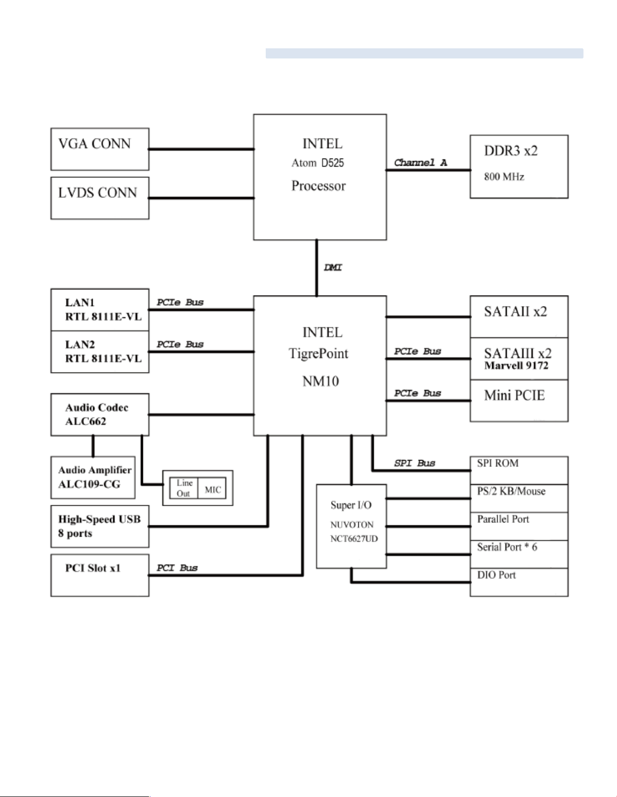
1-3 System Block Diagram
FES2217
Page 9
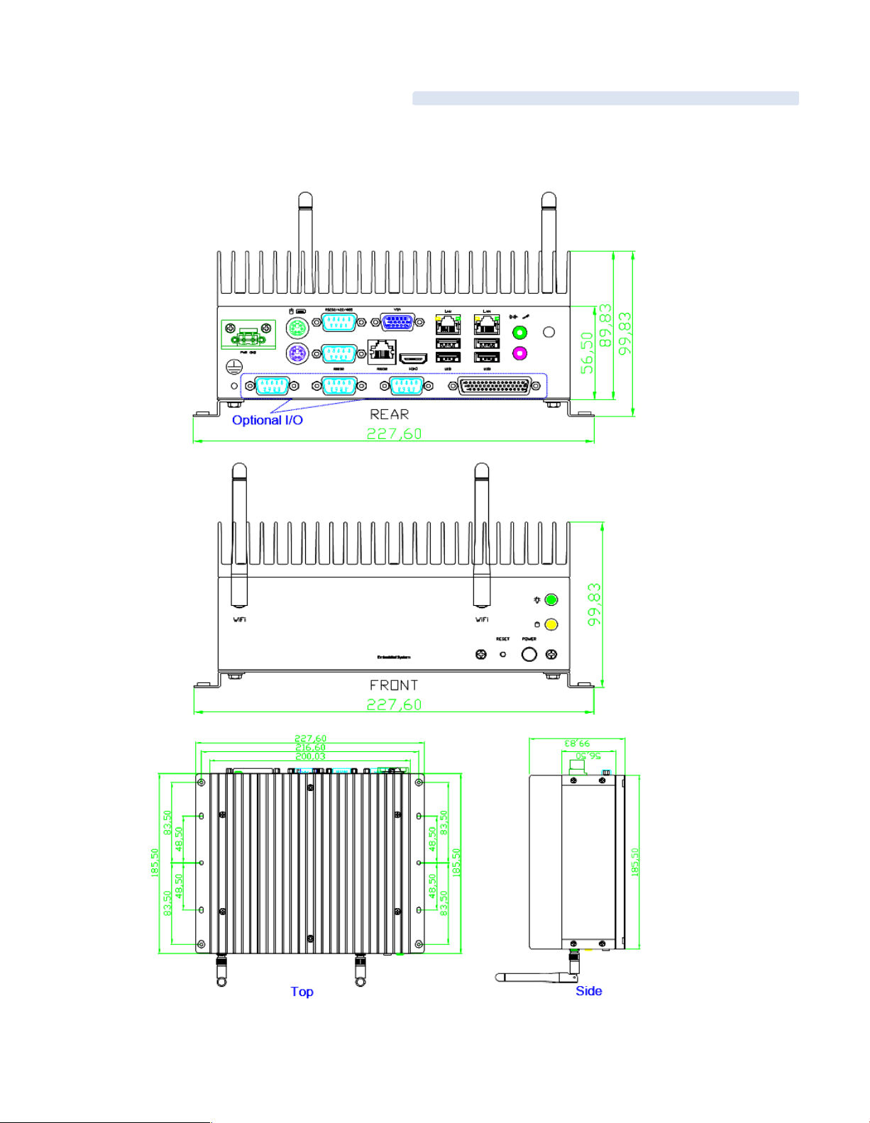
1-4 Mechanical Diagrams
FES 2217
Page 10
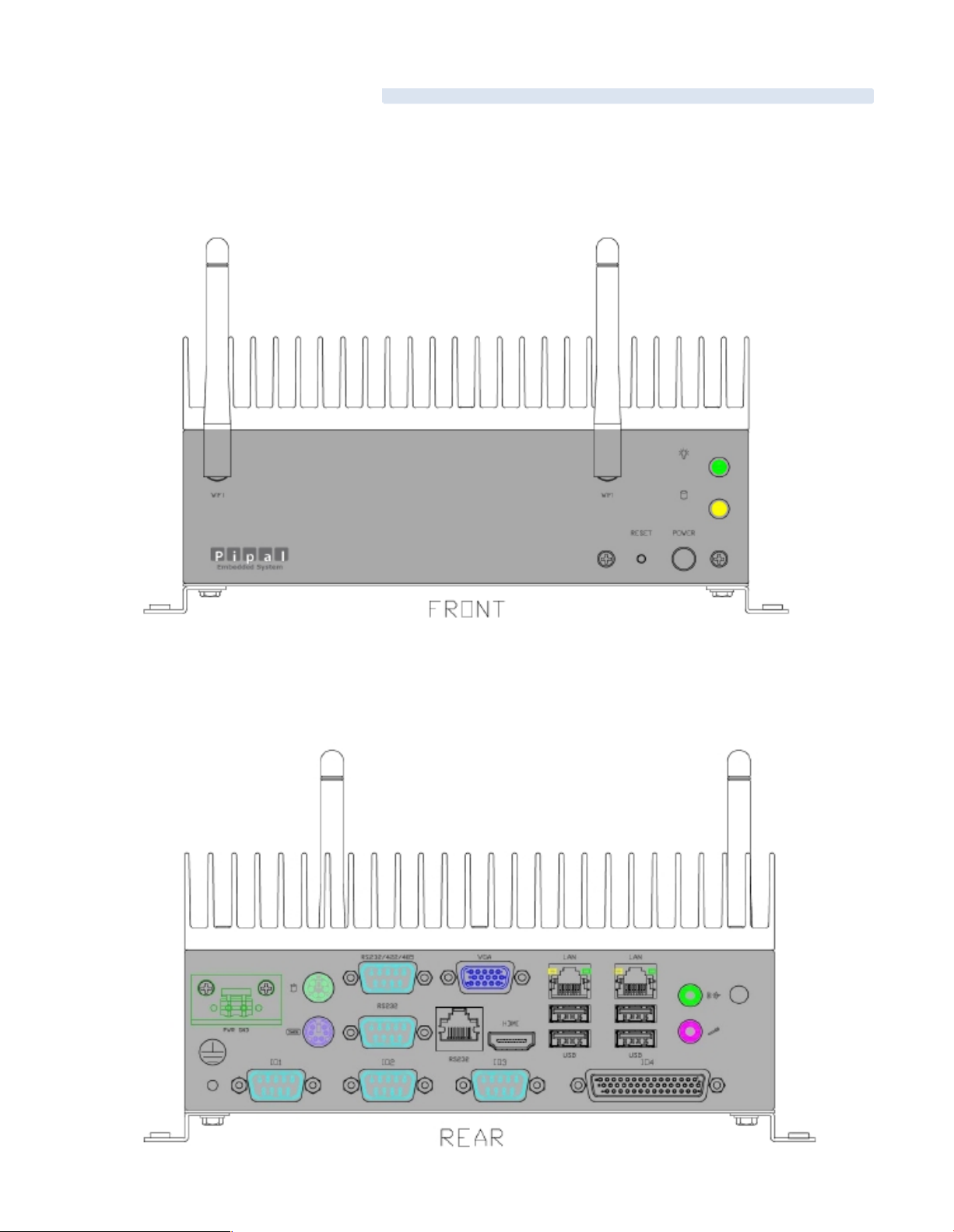
1-5 Front & Rear panel
Front Panel
Rear Panel
Page 11

2-1 Front panel Pin Definition
1. Power On/ Off Button
2. Power Reset Button
3. Power & HDD LED
2-2 Rear Panel Pin Definition
Chapter 2: Pin Definition & Jumper Settings
Page 12

2, 10, & 11: COM Port 1, 2, 3 (DB-9): RS-23 2/ 422/ 485
PIN
RS-232
RS-422
RS-485
1
DCD#
TX+
RTX+
2
RXD
RX+
Not Used
3
TXD
TX-
RTX-
4
DTR#
RX-
Not Used
5
GND
GND
GND
6
DSR#
Not Used
Not Used
7
RTS#
Not Used
Not Used
8
CTS#
Not Used
Not Used
9
RI#
Not Used
Not Used
3. VGA Port (VGA 1)
4 & 5: LAN 1 & 2 (RJ-45)
PIN
Definition
PIN
Definition
1
Lan_TX1+
2
Lan_TX1-
3
Lan_TX2+
4
Lan_TX3+
5
Lan_TX3-
6
Lan_TX2-
7
Lan_TX4+
8
Lan_TX4-
6: Line-Out Connector
PIN
Definition
PIN
Definition
1
LINE_OUT_Left
2
LINE_OUT_Right
3
AUDIO_AGND
4
AUD IO_AGND
5
LINE_IN_Left
6
LINE_IN_Right
7
AUDIO_AGND
8
AUD IO_AGND
9
Micro phone_IN1
10
Micro phone _IN2
8 & 9: USB Connector
PIN
Signal
PIN
Signal
15V5
5V
2D-6
D-
3D+7
D+
4
GND
8
GND
Page 13

2-3 Internal Pin Definition & Jumper Settings
2-3.1 Main Board Top V iew
Page 14

2-3.2 Main Board Pin Definition
Page 15
2-3.3Jumper Settings
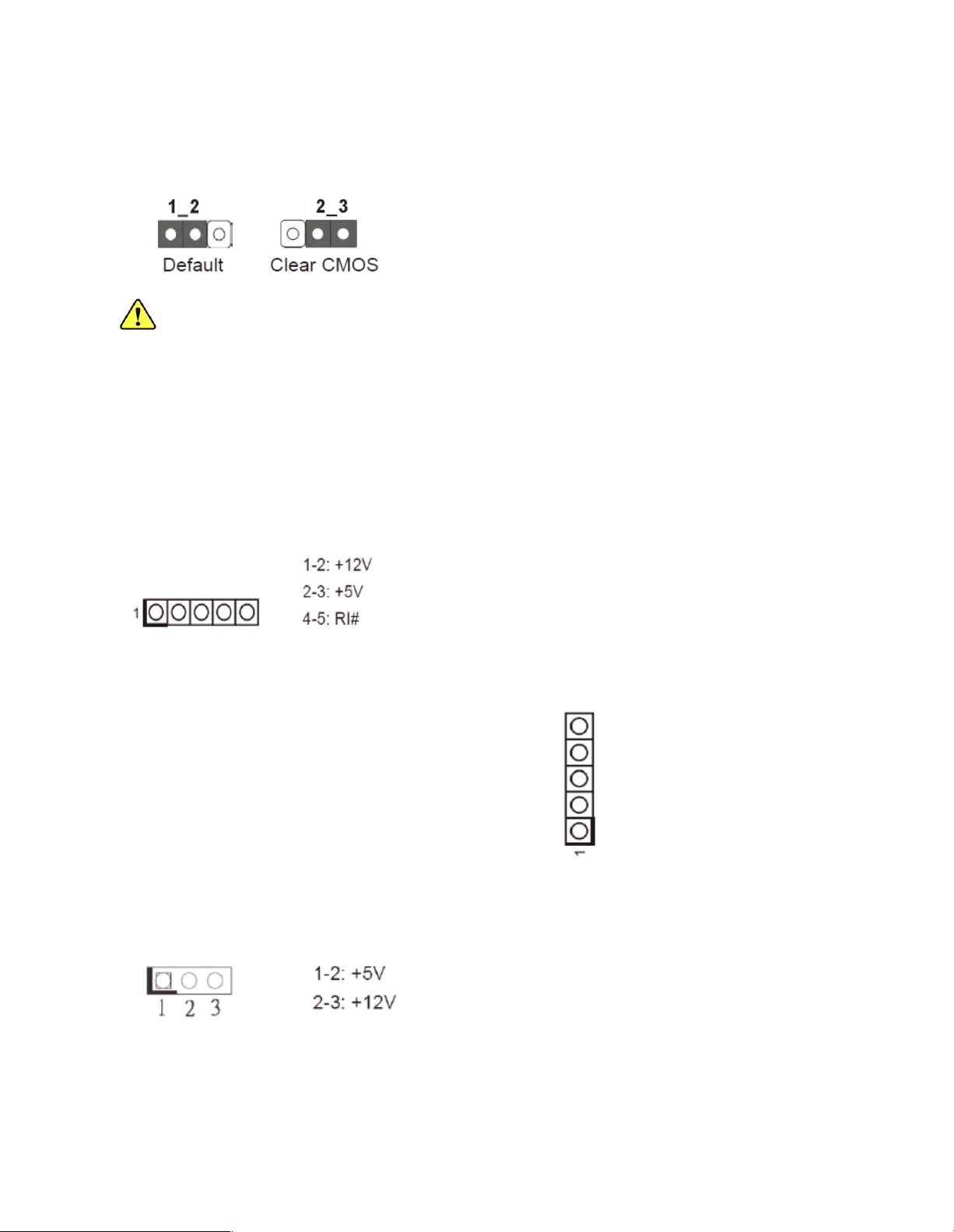
1. Clear CMONS Jumper (CLRCMOS1) [refer to P.14, No. 26]
It allows you to clear the data in CMONS. To clear and reset the system parameters to default
setup, please turn off the computer a nd unplug the power cord from the pow er supply. After
waiting for 15 seconds, use a jumper cap to short pin 2 and pin 3 on CLRCMOS1 for 5 seconds.
However, please do not clear the CMOS right after you update the BIOS. If you need to clear the
CMOS when you just finish updating the BIOS, you must boot up the system first, and the n shut it
down before you do the clear-CMOS action. Please be noted that the password, date, time, user
default profile and MAC address will be cleared only if the CMOS battery is remov ed.
2. COM Port Signal/ Power Setting Jumpers (5-pin SET _CM1) [refer to P.14, No.3]
(5-pin SET_CM2) [refer to P.14, N o.2 ]
(5-pin SET_CM3) [refer to P.14, N o.4 1]
(5-pin SET_CM4) [refer to P.14, N o.3 3]
(5-pin SET_CM5) [refer to P.14, N o.3 4]
(5-pin SET_CM6) [refer to P.14, N o.3 5]
3. Backlight Power Jumper (3-pin BKT_PWR1) [refer to P.14, No.7]
Page 16

4. Panel Power Jumper (3-pin PNL_PWR1) [refer to P.14, No.8]
5. ATX/ AX Mode Jumper (3-pin PWR_JP1) [refer to P.14 , No. 22]
6. Digital Input/ Output Power Setting (3-pin JGPIO_PWR1) [refer to P.14, No.36 ]
7. Serial ATA2 Connectors (SATAII_1) [refer to P.14, No. 16]
(SATAII_2) [refer to P.14, No. 19]
These two Serial ATA2 (SATA2) connectors support SATA data cables for internal storag e
devices. The current SATA 2 interface allows up to 3.0 Gb/s data transfer rate.
8. Serial ATA 3 Connectors (SATA III_1) [refer to P.14, No. 17]
(SATA III_2) [refer to P.14, No. 18]
These two Seria l ATA3 (SATA3) connectors support SATA data cables for internal storage
devices. The current SATA 3 interface allows up to 6.0 Gb/s data transfer rate.
Page 17

9. USB 2.0 Headers (9-pin USB4_5) [refer to P.14, No. 24]
Besides four default USB 2.0 ports on the I/O panel, there are three USB 2.0 headers on this
motherboard. The USB 2.0 headers can support four USB 2.0 ports.
(4-pin USB6) [refer to P.14, No. 25]
(4-pin USB7) [refer to P.14, No. 42]
10. Front Panel Audio Header (9-pin HD-AUDIO1) [refer to P. 14, N o. 32]
This is an interface for front panel aud io cable that allows convenient connection and control
of audio devices.
Page 18
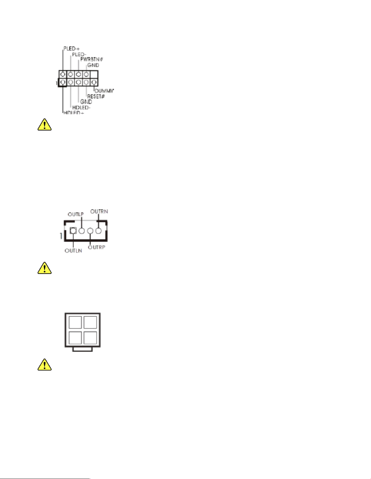
11. System Panel Header (9-pin PANEL1) [refer to P. 14, No. 2 1]
This header accommodates several system front panel functions.
- PWRBTN (Power Switch)
- RESET (Reset Switch)
- PLED (System Power LED)
- HDLED (Hard Drive Ac tivity L ED)
12. 3W Audio AMP Output Wafer Header (4-pin SPEAKER 1) [refer to P.14, No. 30]
Please connect the speaker to this header.
13. 4-Pin Power Connector (4-pin D C 12V1) [refer to P.14, N o. 4]
Please connect a DC 12V power supply to this connector.
Page 19

14. COM Port H eaders (10-pin COM4) [refer to P. 14, N o. 37]
(10-pin COM5) [refer to P. 14, No. 38]
(10-pin COM6) [refer to P. 14, No. 39]
These COM headers support serial port modules.
15. Print Port Header (25-pin LPT1) [refer to P.14, No. 40]
This is an interface for print port cable that allows convenient connection of printer devices.
16. LVDS Panel Connector (40-pin LVDS1) [refer to P.14, No. 9]
Page 20

17. SATA Power Connectors (4-pin JPWR1) [refer to P.14, No. 2 3]
(4-pin JPWR2) [refer to P.14, No. 20]
18. Digital I/O Header (10-pin JG PIO1) [refer to P.14, No. 29]
19. Backlight & AMP Volume Control Header (7-pin BLT_VOL1) [refer to P.14, No. 28]
20. Panel BackLight Inverter Connector (6-pin BLT_PWR1) [refer to P.14, No. 6]
Page 21

Chapter 3: UEFI Setup Utility
3-1 Introduction
This section explains how to use the UEFI SETUP UTILITY to configure yours system. The UEFI chip on the
motherboard stores the U EFI SETUP UTILITY. You may run the UEFI SETUP UTILITY when you start u p th e
computer. Please press <F2> or <Del ete> during the Power-On-Self-Test (POST) to enter the UEFI SE TUP
UTILITY, otherwise, POST will continue with its test routines.
If you wish to enter the UEFI SETUP UTILITY afte r POST, restart the system by pressing <Ctl> + < Alt> +
<Delete>, or by pressing the reset button on the system chassis. You may also restart by turning the system off
And then ba ck on.
3-1.1 UE FI M enu Bar
The top of the screen h as a menu bar with the following selections:
Main: For setting system time/date information
OC Tweaker: For over-clocking configurations
Advanced: For advanced system configurations
H/W Monitor: D isplays current hardware status
Boot: For configuring boot settings and boot priority
Security: For security settings
Exit: Exit the current screen or the UEFI SETUP U TILITY
Use <? > key or < ? > key to choose among the sele ctions on the menu bar, and use <?> key or <?>
key to move the cursor up or down to se lect items, then press <Enter> to get into the sub screen. You
can also navigate with a mouse.
3-1.2 Navigation Keys
Please check the following table for the descriptions of each navigation keys.
Page 22

3-2 Main Screen
Whe n you en ter the UEFI SETUP UTILITY, the Main screen will appear an d display the system overview.
Page 23

3-3 Advanced Screen
In this section, you may set the configurations for the following i tems: CPU Configuration, Chipset Configuration,
Storage Configuration, Super IO Configuration, ACPI Configu ration, U SB Configuration and Voltage Configuration.
Setting wrong values in this sectio may cuase the system to malfunction.
Instant Flash
Instant Flash is a UEFI flash utility embedded in Flash ROM. This convenient UEFI update tool allows you
to update system UEFI without entering operating systems first like M S-DOS or Windows®. Just launch
this tool and save the new UEFI file to your U DB flash drive, floppy disk or hard drive, then you can update
your U EFI only in a few clicks without preparing and additional floppy diskette or other com plicated flsh
utility. Please be noted that the USB flash drive or hard drive must use FAT32/16/12 file system. If you
execute Instant Flash utility, the utility will show the UEFI files and their respective information. Select the
proper U EFI file to update your UEFI, and reboot your system after U EFI update process completes.
Page 24

3-3.1 CPU Configur ation
Intel Hyper Threading Technology
To enable this feature, it requires a computer system with an Intel processor that supports HyperThreading technology and an operating system that includes optimization for this technology, such as
Microsoft® Windows®7. Set to [Enabled] if using Microsoft® Window s®7.
No-Execute Memory Protec tion
No-Execution (N X) Memory Protection Technology is an enhancement to the IA-32 Intel Architecture.
An IA-32 processor with “No Execute (NX) Memory Protection” can prevent data pages from being used by
malicious software to execute code.
Page 25

3-3.2 Chipset Configuration
Set Panel Type by
Use this to configure Set Panel Type.The Default value is [UEFI Setup].
Panel Type Selection
Use this to select panel type . The default va lue is [1366 x768/ 18-bit/ 1-ch/LED ].
ACPI H PET Table
Use this item to enable or disable ACPI HPET Table. The default value is [Enabled]. Please set this
option to [Enabled] if you plan to use this motherboard to submit W indows® certification.
Restore on AC/Power Loss
This allows you to set the power state after an unexpected AC/power loss. If [Power Off] is selected,
the AC/ power remains off when the power recovers. If [Power On] is sele cted, the AC/power resumes
and the system starts to boot up when the power recovers.
Onboard HD Audio
Select [Audio], [Enabled] or [Disabled] for the onboard HD Audio feature. If you select [Auto], the
onboard HD Audio will be disabled when PCI Sound Card is plugged.
Front Panel
Select [Auto] or [Disabled] for the onboard HD A udio Front Panel.
Onboard LAN 1
This allow you to enable or disable the “Onboard LAN 1” feature.
Onboard LAN 2
This allow you to enable or disable the “Onboard LAN 2” feature.
Page 26

3-3.3 S torage Configuration
Onboard SATAII Mode
This item is for SATAII_1 and SATAII_2 ports. Use this to select SATA mode. Configuration opt ions:
[IDE Mode], [AHCI M ode] and [Disabled]. The default value is [IDE M ode].
ACHI (Advanced Host Controller Interface) s upports NCQ and other new features that will improve
SATA disk performance but IDE mode does not have these advantage.
Hard Disk S.M.A.R.T
Use this item to enable or disable the S.M.A.R.T (Self-Monitoring, Analysis, and Reporting Technology)
feature. Configuration options: [Disabled] and [Enabled].
Marvell SATA 3 Operation Mode
This item is for SATAIII_1 and SATAIII_2 ports. Use this to select Marvell SATA3 operation mode. The
default value is [IDE M ode].
Marvell SATA 3 Bootable
Use this to ena ble to disable Onboard Marvell SATA 3 Option ROM. If Option ROM is disabled, UEFI
cannot use the SATA device to connect to Marvell SATA 3 controller as Boot device.
Page 27
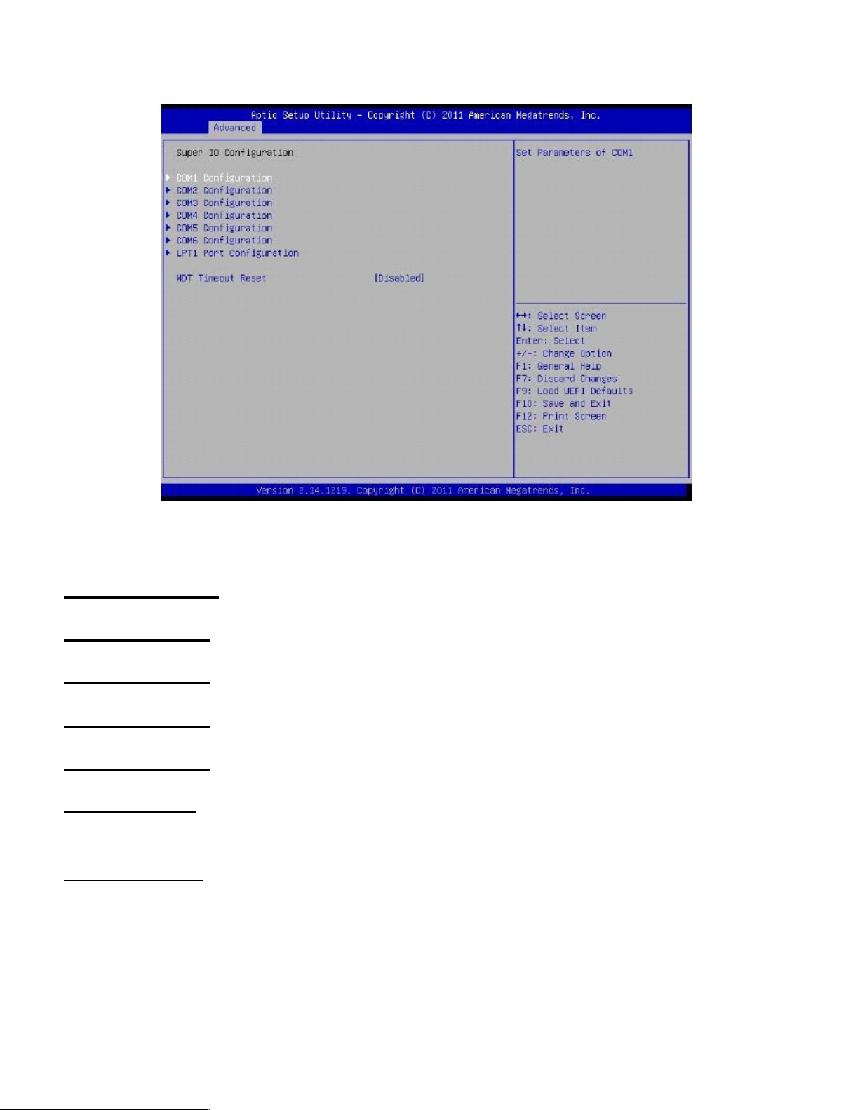
3-3.4 S uper IO Configuration
COM 1 Configuration
Use this to set parameters of COM1.
COM 2 Configuration
Use this to set parameters of COM2.
COM 3 Configuration
Use this to set parameters of COM3.
COM 4 Configuration
Use this to set parameters of COM4.
COM 5 Configuration
Use this to set parameters of COM5.
COM 6 Configuration
Use this to set parameters of COM6.
LPT1 Configuration
Use this to set parameters of the onboard parallel port.
WDT Timeout Reset
This allows users to enable/disable the Watch Dog Timer timeout to reset system. The default value
is [Disabled].
Page 28
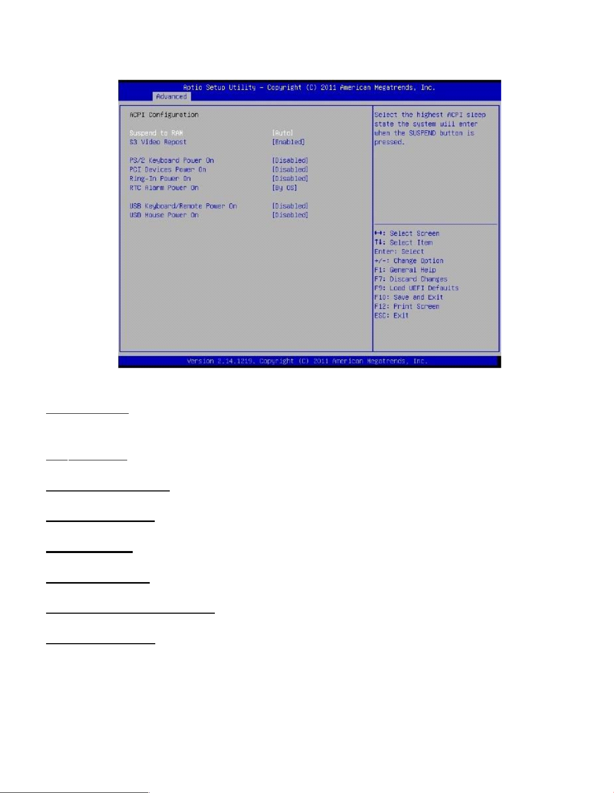
3-3.5 ACPI Configuration
Suspend to RAM
Use this item to select whether to auto-detect or disable the Suspend-to-RAM feature. Select [Auto]
will enable this fe ature if the OS supports it.
S3 Video Repost
Use this to enable/disable S3 Video Repost. The default value is [Enabled].
PS/2 Keyboard Power On
Use this item to enable or disable PS/2 keyboard to turn on the system from the power -soft-off mode .
PCI D evices Power On
Use this item to enable or disable PCI devices to turn on the system from the power-soft-off mode.
Ring-In Power On
Use this item to enable to disable Ring-In signals to turn on the system from the power-soft-off mode.
RTC Alarm Power On
Use this item to enable or disable RTC (Real Time Clock) to power on the system .
USB Keyboard/ Remote Power On
Use this item to enable or disable USB Keyboard/ Remote to power on the system.
USB Mouse Power On
Use this item to enable or disable USB Mouse to power on the system.
Page 29

3-3.6 USB Configuration
USB 2.0 Controller
Use this item to enable or disable the use of USB 2.0 controller.
Legacy U SB Support
Use this option to select legacy support for USB devices. There are four configuration options:
[Enabled], [Auto], [Disabled] and [UEFI Setup Only]. The default value is [Enabled]. Please refer to below
descriptions for the details of these f our options:
[Enabled]: Enables support for legacy USB.
[Auto]: enables legacy support if USB devices are connected.
[Disabled]: USB devices are not allow ed to use under legacy OS and UEFI setup when [Disabled] is
sele cted. If you have USB compatibility issue, it is recomm ended to select [Disabled] to enter OS.
[UEFI Setup Only]: USB devices are allowed to use only under UEFI setup and W indows/ Linus OS.
Page 30

3-4 Hardware Health Event Monitoring Screen
In this section, it allows you to monitor the status of the hardware on your system, including the
parameters of the CPU temperature, mothe rboard temperature, CPU fan speed, chassis fan speed, and the
critical voltage.
CPU_FAN 1 Setting
This allows you to set CPU-FAN 1’s spe ed. Configuration options: [Full On] and [Automatic Mode].
The default value is [Full On].
Page 31

3-5 Boot Screen
In this section, it will display the available devices on your system for you to configure the boot settings and
the boot priority.
Setup Prompt Timeout
This shows the number of seconds to wait for setup activation key.
65535 (0XFFFF) means indefinite wa iting.
Bootup Num-Lock
If this item is set to [On], it wi ll au tomatically activate the Numeric Lock function after boot-up.
Boot From Onboard LAN
Use this item to enable or disable the Boot From O nboard LAN fe ature.
Page 32

3-6 Security Screen
In this section, you may set, change or clear the sup ervisor/ user password for the system.
Page 33

3-7 Exit Screen
Save Changes and Exit
When you sele ct this optino, it will pop-out the following m essage, “Save configuration changes and
exit setup?” Select [OK] to save the changes and exit the UEFI SETUP UTILITY.
Discard Changes and Exit
When you sele ct this option, it will pop-out the following message, “Discard changes and exit setup? ”
Select [OK] to exit the UEFI SETUP UTILITY w ithout saving any changes.
Discard Changes
When you sele ct this option, it will pop-out the following message, “Discard changes?” Select [OK] to
discard all changes.
Load UEFI Defaults
Load UEFI default values for all the setup questions. F9 key can be used for this operation.
Launch EFI Shell from filesystem device
Attempts to Launch EFI Shell application (Shell64.efi) from one of the available filesystem devices.
 Loading...