

Page 1

APW 5240
24” Industrial Panel Mount Widescreen LCD
User Manual
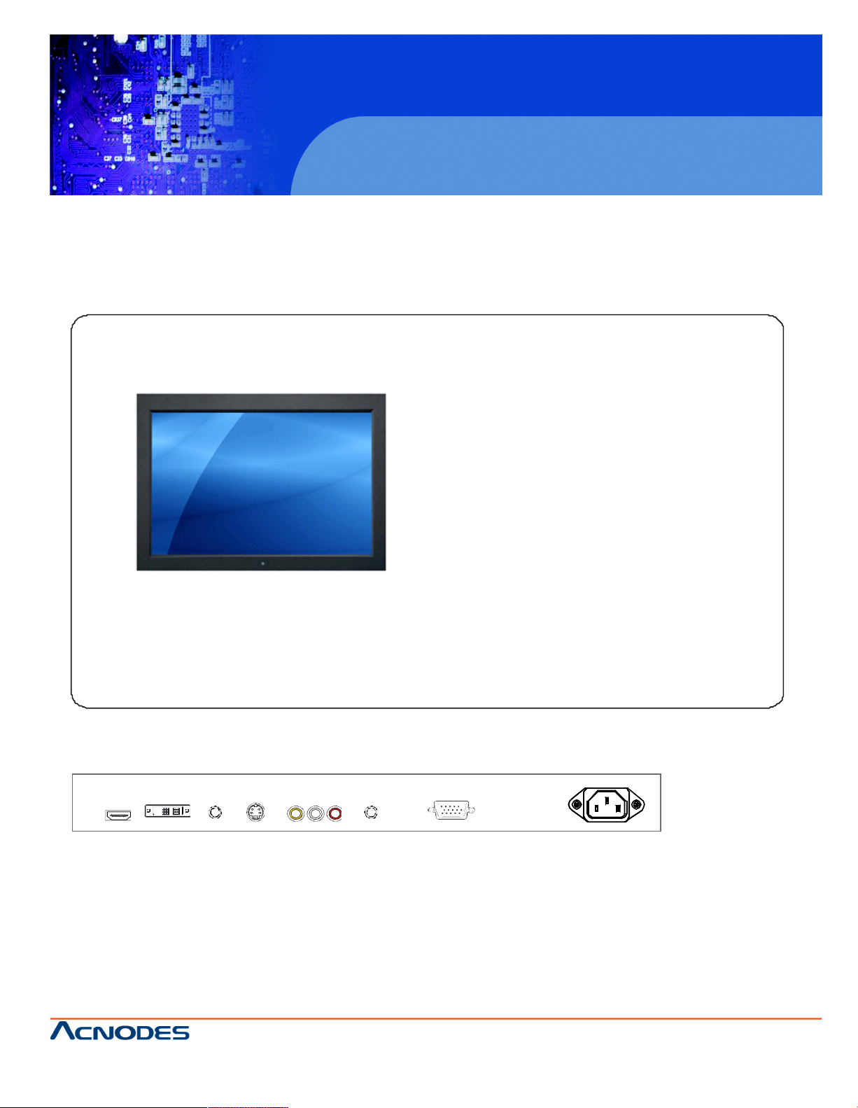
APW5240: 24” industrial panel mount widescreen LCD monitor
14628 Ce ntral Ave,
Chino , CA 91710
tel:909.597.7 588, fax:909.597.1939
© Copyright 2013 Acnodes, Inc.
All righ ts reserved. Product descripti on and product speci ficat ions
are subj ect to change w ith out n oti ce. F or lates t product inform ati on,
ple ase vis it Acnod es’ we b site at www.ac nodes.c om.
Page 2

APW 5240
L eg al Inf orm a tion
F irst English printing , O ctobe r 2 0 02
Inform a tio n in this d oc ument has be e n carefully che c ked for a ccura cy; h o weve r, n o g u aran te e is gi ven to the correc t ne ss
of the con te nt s . T he i n fo rmation i n th is do c um ent is su b ject to ch an g e with o ut n otice. W e a re not li ab le for a ny injury o r
lo s s that re sults from the use of th i s equipm ent.
Sa fet y I nstru ctions
Pl eas e re ad all of th es e in str uctio ns carefully be for e yo u us e th e d e vice. Save this m a nua l for futu re r e fere nc e.
¦ Unp lug equipm ent before clea nin g. D on’t u se liqu id o r s p ray d ete rgent; u se a mois t cloth .
¦ Ke ep e qu i pm ent a w ay fro m ex cessive h um i d ity a nd h e at. Prefe ra bl y, k ee p it in a n ai r -condition e d e n v ir on m e nt with
temperat ures n ot exceed ing 40º C e lsi us (104º F ah ren he it).
¦ When ins ta lling, place th e eq uip m e nt o n a stu rd y, level su rface to p revent it from a ccidenta lly fa lling an d causi n g d a m
age to oth er e q u ipm e nt or injur y to p erso n s nea rb y.
¦ When the equip me nt is in an open position, d o no t cove r, b lo ck o r in a ny wa y o bstruct th e g ap b e tw een it a n d th e
powe r s u p pl y. Proper a ir co n vection is nece ssary to k ee p it f rom ove rhea ting.
¦ A rra ng e th e e qu i pm ent ’s po w er cord in su c h a wa y t ha t ot he rs w on’ t tri p or fall o ver it.
¦ If you a re u sing a p o wer cord th at d id n ’t sh ip w ith the e qu ipment, en sure t h at it is rated for th e v o ltage and cur rent
la be le d o n th e eq u i pm e n t ’s ele ctric al ra ti ng s label. The volta ge rating on the co rd should b e high e r tha n th e on e list ed
on the equ ipment ’s rat ings l ab e l.
¦ Ob s erv e all preca utio n s and w a rnin gs at ta ched to the e q uipment.
¦ If you d o n’t intend on u sing t he eq ui p m e nt fo r a lon g tim e , d iscon n ec t it from th e po wer ou tlet to p re v en t be ing d a m
aged by tr ansien t ov e r -v oltage.
¦ Ke ep a l l liq uids a way fr om the equip m ent to mini m ize the risk of accidenta l sp ill ag e . L iqu id spi lled o n to th e pow er
su p pl y or o n o the r hard ware m a y cause d am a g e, fire or e lectric a l sh o ck.
¦ On l y qualif ied servi ce person ne l sh ou l d op e n th e c ha ssis. O pen in g it you rself could damage the e q uipm ent and inv a li
date its w arra n t y.
¦ If any p a rt of th e eq u ipm e nt b ecomes damaged or st op s functi o ning, have it c hecke d by q u alified servic e pe rso nn e l.
W hat the w arr an ty d oes not co ver
¦ A n y prod u c t, on wh ich the se ri al number h a s b ee n d ef ac e d , m o d ified or rem ove d.
¦ Dam a g e, d ete rioration or malfunction re s u lting from :
? Ac cide nt , m isuse, n eg l ect, fire, wa te r, lig h tn ing, or o th e r acts o f na tu re, un au th o rized pro d uc t m o difica tion, or
failure t o follow instructi o ns sup plied with the pro du ct.
? Repair or a tte m p te d rep a ir b y anyo ne not authorized by us .
? An y da m a g e o f th e product due to shi p m en t.
? Removal o r i ns tallation of the pro du ct.
? Cause s extern a l to the p rod uc t , such as e lectric p o we r fluc tu a tion o r f ai lure .
? Use o f sup p lies or pa rts not m ee tin g ou r s p e cificatio ns .
? Norm a l we ar an d te a r.
? An y ot he r c a u ses whic h do e s not re la te t o a product def ec t .
¦ Rem o val, i nstalla tion, and s et -u p s e rv ice c h a rges.
Re gulato ry N otic e s Fede r al Co mm unicati ons Com m is si on (FCC )
T his e q ui p m en t ha s b e en t ested a nd f ou n d to c o m p ly w ith th e limi ts for a C lass B digital d evic e , p u rsua n t t o Part 15 of the
F CC rules . These limits are de s igned to pro v ide re a son a ble prot ection agains t h armful in te rfe ren ce in a resi d en tial ins ta l la ti on .
An y changes or m o dificat ions m a d e to this equipm e nt may v o id the use r’s au th o rity to o p erate this e q uipm ent. Th i s
equip m en t ge n erate s, use s , a n d can ra d ia te radio f requency e n ergy a n d, if n o t instal led and use d i n acco rdance with the
in s tr uctions, m ay cause ha rmful i nt erfere n ce to ra di o communicat ions.
Ho we ver, t he re is no g u ar antee th a t interfe rence wil l not occ ur in a p art icular ins t allat io n . I f th is e qu ipm e n t do e s ca us e
harm fu l interfe rence to radio or te levis ion recep tio n, w h ich c an b e de ter min e d b y turn in g t he eq u ipm e nt o ff a nd o n , th e
use r is en courag e d t o try to co rrect th e interfe rence b y o n e or more o f th e fo llowing m easu res:
¦ Re -p os itio n or relocate the receiv ing anten n a.
¦ Increase the se pa ration be tw een the equipm ent a nd rec e ive r.
¦ Con ne ct the equipment int o an ou tl et o n a circuit d i fferen t from that t o wh ich the receiv er is connect ed .
24” Industrial Panel Mount Widescreen LCD
14628 Ce ntral Ave,
Chino , CA 91710
tel:909.597.7 588, fax:909.597.1939
© Copyright 2013 Acnodes, Inc.
All right s reser ved . Produc t descr ipt ion and product speci fi cat io ns
are subj ect to change w ith out n oti ce. F or lates t product inform ati on,
ple ase vis it Acnod es’ we b site at www.ac nodes.c om.
Page 3

Contents
< Part. 1 > APW 5240
1.1 Package Content
1.2 Structure Diagram & Dimension
1.3 Mounting Hardware & Installation
P.1
P.2 - 3
P.4 - 5
< Part. 2 > Product Specifications & LCD OSD
2.1 Product Specifications
2.2 On-screen Display Operation ( OSD )
2.3 Remote Controller ( RC-2 )
P.6 - 7
P.8 - 9
P.10
< Part. 3 >
Options
3.1 Option Table
3.2 3G / HD / SD-SDI Broadcast-grade input
3.3 MCS Multi-display control solution
3.4 24" Touchscreen : Resistive
3.5 MIL-type or lockable connector
3.6 TV ( Analog )
P.11
P.12
P.13
P.14
P.15
P.16
APW 5240
24” Industrial Panel Mount Widescreen LCD
14628 Ce ntral Ave,
Chino , CA 91710
tel:909.597.7 588, fax:909.597.1939
© Copyright 2013 Acnodes, Inc.
All righ ts reserved. Product descripti on and product speci ficat ions
are subj ect to change w ith out n oti ce. F or lates t product inform ati on,
ple ase vis it Acnod es’ we b site at www.ac nodes.c om.
Page 4

APW 5240
Before Installation
¦ It is very important to mount the equipment in a suitable cabinet or on a stable surface.
¦ Make sure the place has a good ventilation, is out of direct sunlight, away from sources of excessive
dust, dirt, heat, water, moisture and vibration.
Unpacking
The equipment comes with the standard parts shown in package content. Check and make sure they are
included and in good condition. If anything is missing, or damaged, contact the supplier immediatel y.
How To Clean Your LCD Monitor
Caution :
¦ To avoid the risk of electric shock, make sure your hands are dry before unplugging your monitor from or
plugging your monitor into an electrical outlet.
¦ When you clean your monitor, do not press down on the LCD screen. Pressing down on the screen can
scratch or damage your display. Pressure damage is not covered under warrant y.
¦ Use only cleansers made specifically for cleaning monitors and monitor screens. Cleansers not made to
clean monitors and monitor screens can scratch the LCD display or strip o ff the finish.
¦ Do not spray any kind of liquid directly onto the screen or case of your monito r. Spraying liquids directly
onto the screen or case can cause damage which is not covered under warrant y.
¦ Do not use paper towels or abrasive pads to clean your monito r. Using an abrasive pad or any wood based
paper product such as paper towels can scratch your LCD screen.
Cleaning Your Monitor
To clean your LCD safely, please follow these steps :
1
Disconnect the power cord.
2
Gently wipe the surface using a clean, dry microfiber cloth. Use as little pressure as possible.
Cleaning Tough Marks and Smudges
To remove tough marks and smudges, please follow these steps :
1
Disconnect the power cord.
2
Spray a small amount of non-abrasive cleanser on a microfiber cloth.
Caution : Do not spray or apply any liquids directly onto the monitor. Always apply the solution to your
microfiber cloth first, not directly on the parts you are cleaning.
3
Gently wipe the surface. Use as little pressure as possible.
4
Wait until your monitor is completely dry before plugging it in and powering it up.
24” Industrial Panel Mount Widescreen LCD
14628 Ce ntral Ave,
Chino , CA 91710
tel:909.597.7 588, fax:909.597.1939
© Copyright 2013 Acnodes, Inc.
All right s reser ved . Produc t descr ipt ion and product speci fi cat io ns
are subj ect to change w ith out n oti ce. F or lates t product inform ati on,
ple ase vis it Acnod es’ we b site at www.ac nodes.c om.
Page 5
< Part 1 >
< 1.1 > Package Content – APW 5240
APW 5240
24” Widescreen LCD display X 1
6ft VGA cable X 1
Power cord X 1
Remote controller X 1
Mounting hardware X 1 pack
- Mounting bracket x 4 pcs
- M4* 6mm screw x 8 pcs
- M4* 50mm screw x 8 pcs
Standard I/O
HDMI DVI-D
Audio
S-Video
R C A
Audio
VGA
Power
in out
APW 5240
24” Industrial Panel Mount Widescreen LCD
14628 Ce ntral Ave,
Chino , CA 91710
tel:909.597.7 588, fax:909.597.1939
© Copyright 2013 Acnodes, Inc.
All righ ts reserved. Product descripti on and product speci ficat ions
are subj ect to change w ith out n oti ce. F or lates t product inform ati on,
ple ase vis it Acnod es’ we b site at www.ac nodes.c om.
Page 6
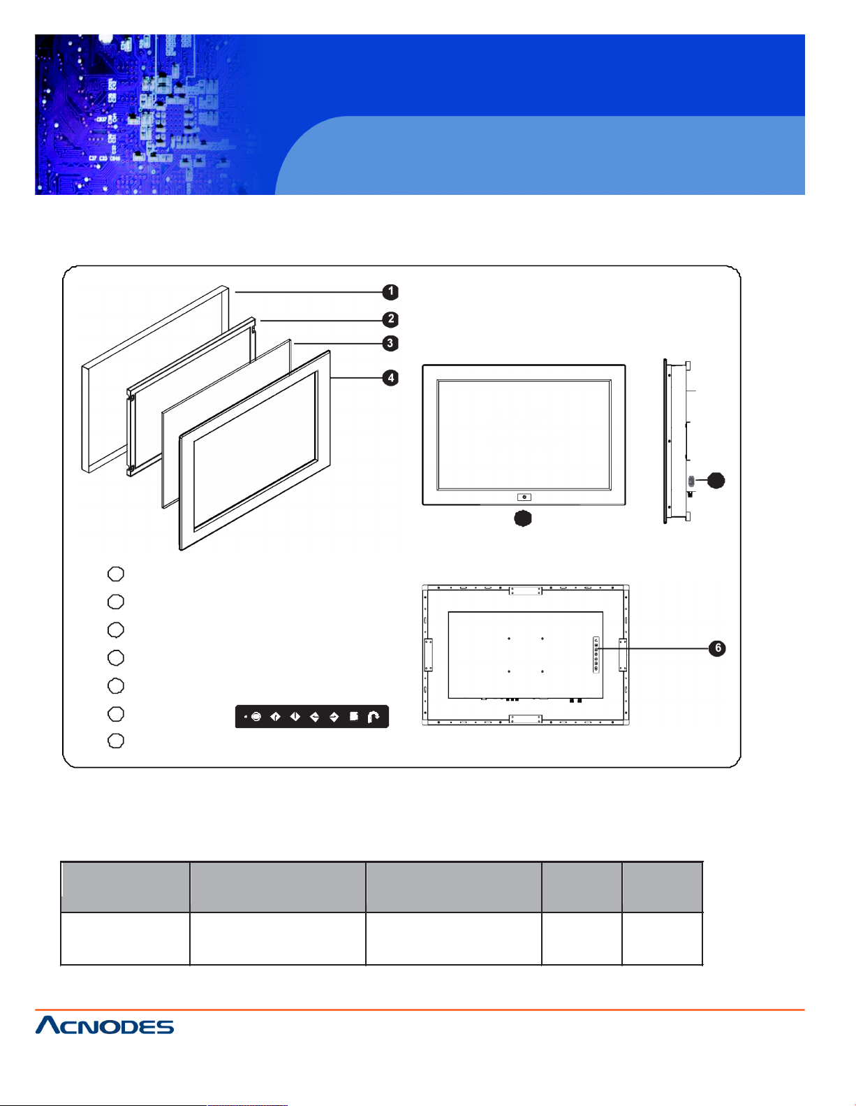
< 1.2 > Structure Diagram - APW 5240
1
2
3
Front view
4
AP-X24
NAP-X24
5
7
1 Rear case
2 LCD panel
3 Protective 3mm glass
4 6mm aluminum front bazel
5 Audio speaker, pair
6 LCD membrane
7
Remote sensor
Rear view
6
Model
Product Dimension
(W x D x H)
Packing Dimension
(W x D x H)
Net
Weight
Gross
Weight
APW5240
620 x 87 x 426 mm
24.4 x 3.4 x 16.8 inch
701 x 138 x 685 mm
27.6 x 5.4 x 27 inch
10 kg
22 lbs
14 kg
31 lbs
APW 5240
24” Industrial Panel Mount Widescreen LCD
14628 Ce ntral Ave,
Chino , CA 91710
tel:909.597.7 588, fax:909.597.1939
© Copyright 2013 Acnodes, Inc.
All right s reser ved . Produc t descr ipt ion and product speci fi cat io ns
are subj ect to change w ith out n oti ce. F or lates t product inform ati on,
ple ase vis it Acnod es’ we b site at www.ac nodes.c om.
Page 7

< 1.2 > Dimension - APW 5240
Front View Side View
AP-X24
NAP-X24
Rear View
UNIT : mm
1mm = 0.03937 inch
Bottom View
Page 8

< 1.3 > Panel Mount Installation – APW 5240
1
Mounting
bracket
x 4 pcs
2 M4*6mm screw
x 8 pcs
3
M4*50mm screw
x 8 pcs
Hardware set part no. UV-BK#2
Steps
¦ Install 4 mounting brackets with 8 x M4*6mm screws
¦ Adjust the LCD panel with 8 x M4*50mm screws and fix it on the surface.
APW 5240
24” Industrial Panel Mount Widescreen LCD
14628 Ce ntral Ave,
Chino , CA 91710
tel:909.597.7 588, fax:909.597.1939
© Copyright 2013 Acnodes, Inc.
All right s reser ved . Produc t descr ipt ion and product speci fi cat io ns
are subj ect to change w ith out n oti ce. F or lates t product inform ati on,
ple ase vis it Acnod es’ we b site at www.ac nodes.c om.
Page 9

APW 5240
< 1.3 > VESA mount Installation – APW 5240
M4 screw
VESA mount ( 100*100mm )
¦ Hardware and M4*4 pcs for VESA mount are not provided
24” Industrial Panel Mount Widescreen LCD
14628 Ce ntral Ave,
Chino , CA 91710
tel:909.597.7 588, fax:909.597.1939
© Copyright 2013 Acnodes, Inc.
All righ ts reserved. Product descripti on and product speci ficat ions
are subj ect to change w ith out n oti ce. F or lates t product inform ati on,
ple ase vis it Acnod es’ we b site at www.ac nodes.c om.
Page 10

< Part 2 >
< 2.1 > Product Specifications
Mechanical
Design
APW 5240
Front Panel
Black, RAL 9005
Rear Casing
Dark grey, RAL 7037
VESA Mounting
100 x 100mm
Other Mounting
Panel mount
Protection
3mm protective glass
LCD
Panel
Panel Size ( diagonal )
24.1-inch Widescreen TFT color LCD
Display pixel ( dots x lines )
1920 x 1200
Brightness ( typ. )
400
Contrast Ratio ( typ. )
1000:1
Color
1.07 b
Viewing Angle ( L/R/U/D )
89/89/89/89
Response Time ( ms )
13
Dot pitch ( mm )
0.27
Display Area ( mm )
518.40H x 324.0V
Surface treatment
Anti-glare, Hard-coating
Surface hardness
3H
Backlight Type
LED
MTBF ( hrs )
40,000
Video
Connectivity
Digital
HDMI
HDMI 1.1, CEA-861-D
DVI
DVI-D, TMDS single link
Analog
VGA
Analog 0.7Vp-p
Composite ( RCA )
NTSC & PAL
S-Video ( 4-pin )
NTSC & PAL
Plug & Play
DVI / VGA
VESA EDID structure 1.3
Synchronization
VGA
Separate, Composite & SOG
Audio
Connectivity
Audio Input
Connector
3.5mm st ereo jack
Impedance / Power level
30kΩ / 750mV
Audio Output
Connector
3.5mm stereo jack
Resistance / Power level
30kΩ / 2.8V
Speaker Output
Power
2 x 2W
*When the audio output is connected, speake r output is OFF
Power
Power Supply
Range
Auto-sensing 100 to 240VAC,
50 / 60Hz
Power Consumption
Screen display ON
125W or less
Power saving mode
9W or less
Power button OFF
2W or less
Page 11

Regulatory Safety Approval FCC & CE
Environmental
Conditions
Operating
Temperature
0 to 50°C degree
Humidity
20~90%, non-condensing
Storage
Temperature
-5 to 60°C degree
Humidity
5~90%, non-condensing
Shock
10G acceleration (11ms duration)
Vibration
5~500Hz 1G RMS random
Physical
Specification
Product ( W x D x H )
620 x 87 x 426 mm
24.4 x 3.4 x 16.8 inch
Packing ( W x D x H )
701 x 138 x 685 mm
27.6 x 5.4 x 27 inch
Net Weight
10 kgs / 22 lbs
Gross Weight
14 kgs / 31 lbs
Applicable
Format
DVI-D / VGA Input
PC Signal
1920 x 1200 x 60Hz
1920 x 1080 x 60Hz
1280 x 1024 x 60 / 75Hz
1280 x 960 x 60Hz
1280 x 768 x 60 / 75Hz
1152 x 864 x 75Hz
1024 x 768 x 60 / 70 / 75Hz
848 x 480 x 60Hz
800 x 600 x 60 / 72 / 75Hz
720 x 400 x 70Hz
640 x 480 x 60 / 72 / 75Hz
640 x 400 x 70Hz
640 x 350 x 70Hz
HDMI Input
PC Signal
Same as VGA
Video Signal
1080p : 60Hz
720p : 50 / 60Hz
480p : 60Hz
576p : 50Hz
Audio Signal
2ch Linear PCM ( 32 / 44.1 / 48 KHz )
Composite / S-Video
Input
NTSC
525 lines, 60 fields / sec
PAL
625 lines, 50 fields / sec
Page 12

< 2.2 > On-screen Display Operation ( OSD )
Power light
Green = On
Orange = Power saving
Membran e Switch Function
Power on / off LCD
Display the OSD menu
Scrolls through menu options and adjusts the displayed control
(To auto adjustment by p ressing the button for 5 seconds)
Exit the OSD screen
Toggle analog, digital & video connection (DVI-D and video options only)
1
Picture
Picture mode : Standard / Vivid / Soft / User mode to choose
Brightness : Adjust background black level of the screen image
Contrast : Adjust the difference between the image background
(black level) and the foreground (white level)
Hue: Adjust the screen hue value
Saturation : Adjust the saturation of the image color
Picture size : Adjust the image size
Color temp : Standard / Cool / Warm / User to choose
Noise reduce : Reduce the noise of the image
Sharpness : Adjust the image from weak to sharp
2
PC
Auto adjust : Automatically adjust sizes, centers and fine tunes the
video signal to eliminate waviness and distortion.
Clock : Adjust the clock value
Phase : Adjust the phase value
H. Position : Align the screen image left or right
V. Po sition : Align the screen image up or down
Page 13

< 2.2 > On-screen Display Operation ( OSD )
3
Audio
Audio mode : Movie / Voice / Normal / Music mode to choose
Volume : Adjust the volume of sou nd
Bass : Set the value of bass sound
Treble : Set the value of treble sound
Balance : Set the balance value of treble and bass sound
Analog TV audio : Set the value of analog TV audio sound
Mute : Turn off the surrounding sound
4
TV
Auto search : Automatically search
Manual search : Search the TV manual
Fine tune : Fine tun e the TV signal
Color system : Adjust the TV color
Sound system : Adjust the TV sound
Channel edit : Edit the channel
5
MISC
Language : Select the language in which the OSD menu is
displayed - English
Sleep timer : Set the off time
PIP mode : Adjust picture in picture setting
PIP position : Enter into PIP position
PIP source : Enter into the Sub source and sound source
System reset : Return the adjustment back to factory setting
Information : Select for Help
Page 14

r
< 2.3 > Remote Controller ( RC-2 )
1
8
2
INPUT MUTE
VOL
9
1 2 3
3
4 5 6
7 8 9
4
AUTO
0
-/--
CH
10
FRE EZE
11
12
5
MENU SELE CT A SPEC T
13
14
6
ENTER
SLEEP
15
7
BACK EXIT
16
PIP
17
20
SOURC E
21
SWAP
PIP
POSITION
PIP
AUDIO
18
19
1
INPUT Select the source
2
Switches on or off the TV
3 0 - 9
Only use in TV mode. Select channels. For chann el numbers 10
and above, enter the second digit within two seconds.
4 AUTO Auto adjust
5 MENU Display the menu on the screen or go to the previous menu
Go to the upper menu or select the previous value /
Go to the next menu or select the next value /
6
? / ? / ? / ? / ENTER Decrease th e setting value /
Increase the setting value or en ter to the select item setting
Enter to the select item settings or excude the setting
7
BACK Back to previous value
8
MUTE Turn on or off the speaker
9
Vol + / - Increase or decrease the speaker volume
10 CH + / - For TV model only, increase o r decrease the chan nel number
11
FREEZE Reserve for OE M model
12 - / -- For setting input single or double digits
13
ASPECT Adjust the scr een size
14 SELECT To select the existing ite m
15
SLEEP Select the sleeping time
16
EXIT Exit the menu or cancel
PIP functions
17 PIP Picture in picture
18
PIP AUDIO To set the audio of in PIP mode
19 POSITION To set the screen position in PIP mode
20
SOURCE PIP So urce
21 SWAP Swap screen in PIP mode
Page 15

APW 5240
< Part 3 > Options
24” Ultra H igh Res LCD Display
< 3.1 > Option Table
Options
APW
PMW
SDI ***
Touchscreen
MCS multi-display control ***
MIL-type / lockable connector
TV
***
The user can only select either SDI or MCS inputs.
24” Industrial Panel Mount Widescreen LCD
14628 Ce ntral Ave,
Chino , CA 91710
tel:909.597.7 588, fax:909.597.1939
© Copyright 2013 Acnodes, Inc.
All righ ts reserved. Product descripti on and product speci ficat ions
are subj ect to change w ith out n oti ce. F or lates t product inform ati on,
ple ase vis it Acnod es’ we b site at www.ac nodes.c om.
Page 16

< 3.2 > Options : 3G / HD / SD-SDI input
Acnodes’ SDI input is an ideal solution for the broadcastgrade video and high resolution CCTV market.
Designed for use with Full HD 1080p and ultra high resolution
1920 x 1200 LCD displays, Acnodes provides a SDI input
module without using additional space or power and it comes
standard with a 2-year warranty.
Power BNC S-Video
Audio
out - in - in
Video PC
HDMI
DVI-D VGA
SDI
out - in
INPUT
3G-SDI IN
BNC x 1 / 0.8Vp-p ( 75 ohm )
3G-SDI OUT
BNC x 1 / Active through, equalized & relocked
Standard Compliance
Video
SMPTE 425M / 274M / 296M / 125M
ITU-R BT.656
Audio
SMPTE 299M / 272M-C
Compatible Video Format
3G-SDI
1080p @60 / 50Hz, 4:2:2
1080p @30 / 25 / 24Hz, 4:4:4
1080i @60 / 50Hz, 4:4:4
720p @60 / 50Hz, 4:4:4
HD-SDI
1080p @30 / 25 / 24Hz, 4:2:2
1080i @60 / 50Hz, 4:2:2
720p @60 / 50Hz, 4:2:2
SD-SDI
480i @60Hz, 4:2:2
ITU-R BT.656
576i @50Hz, 4:2:2
Compatible Audio Format
3G-SDI
48kHz, 16 / 20 / 24 bit, 2 CH, Synchronized Video
HD-SDI
48kHz, 16 / 20 / 24 bit, 2 CH, Synchronized Video
SD-SDI
48kHz, 16 / 20 / 24 bit, 2 CH, Synchronized /
Asynchronized Video
Max. Transmission Distance
75 ohm coaxial cable
3G-SDI
150m at 2.97Gb/s
HD-SDI
250m at 1.485Gb/s
SD-SDI
480m at 270Mb/s
APW 5240
24” Industrial Panel Mount Widescreen LCD
14628 Ce ntral Ave,
Chino , CA 91710
tel:909.597.7 588, fax:909.597.1939
© Copyright 2013 Acnodes, Inc.
All right s reser ved . Produc t descr ipt ion and product speci fi cat io ns
are subj ect to change w ith out n oti ce. F or lates t product inform ati on,
ple ase vis it Acnod es’ we b site at www.ac nodes.c om.
Page 17

< 3.3 > Options : MCS
MCS
( Multi-display Control )
More control is always good. Especially when it is necessary and
easy. Acnodes provides MCS solution to control the O SD of
various LCD display up to 64 units.
The RS-232C is used for the communication between the PC and
the first display via a 15 feet serial cable while the CAN bus is
used for the various LCD displays cascade together via CAT 5/6
cable, and daisy chain up to 1,000 meters.
Designed for use with various LCD displays, Acnodes provides
a MCS input module without using additional space or power
and it comes standard with a 2-year warranty.
MCS
Power BNC S-Vi deo
Audio
out - in - in
Video PC
HDMI
DVI-D VGA
set out in Link
RS-232C
Set switch
For the 1st and last display,
push the set switch upward
15 feet serial cable
( over 15 feet, extender required )
For other daisy chain displays,
push the set switch downward
LINK OUT
IN OUT IN OUT IN OUT
Cat5 / 6 cable
max. 300 meters
Cat5 / 6 cable
max. 300 meters
Cat5 / 6 cable
max. 300 meters
RJ-45 jack
Daisy chain up to 1,000
meters and 64 displays
up to 64 displays
Page 18

< 3.4 > Options : Touchscreen & driver
24" USB Touchscreen Specification
Model
Technology
Touch Point
Method
Activation Force
Durability
Response Time
Optical Transmittance
Surface Hardness
Haze
Glass
Connector
Compatibility
TRB e-Resistive
5-Wire Resistive
Single
Stylus or Finger
= 50g / Stylus=R0.8
10 million touches
15 ms
80% ± 3%
3H
8% ± 3%
3.2 ±0.2 mm
USB Type A
Windows 7 / XP / Vista, Linux
¦ USB touchscreen package includes 1 x 6ft USB cable, quick reference guideline and CD disc
¦ For detailed information, please refer to the attached CD disc
¦ As the touchscreen unit is not made of toughened glass, please handle it carefully
USB Touchscreen
HDMI DVI-D Audi oinS-Video R C A Audio
out
VGA Power
APW 5240
24” Industrial Panel Mount Widescreen LCD
14628 Ce ntral Ave,
Chino , CA 91710
tel:909.597.7 588, fax:909.597.1939
© Copyright 2013 Acnodes, Inc.
All right s reser ved . Produc t descr ipt ion and product speci fi cat io ns
are subj ect to change w ith out n oti ce. F or lates t product inform ati on,
ple ase vis it Acnod es’ we b site at www.ac nodes.c om.
Page 19

APW 5240
Please follow the below steps to s etup the touch screen:-
Step 1. Run the bundled CD disc
Step 2. Double click the Setup.exe
Step 3. Follow the installation instruction to finish the setup
Step 4. After installation, run the TouchKit program & the “4 point calibration”
Please do the initial calibration
after the first setup
24” Industrial Panel Mount Widescreen LCD
14628 Ce ntral Ave,
Chino , CA 91710
tel:909.597.7 588, fax:909.597.1939
© Copyright 2013 Acnodes, Inc.
All righ ts reserved. Product descripti on and product speci ficat ions
are subj ect to change w ith out n oti ce. F or lates t product inform ati on,
ple ase vis it Acnod es’ we b site at www.ac nodes.c om.
Page 20

APW 5240
< 3.5 > Options : MIL-type or Lockable Connector
Input
Part no.
MIL Standard
MIL - type
Connector
DC Power ***
( Male )
MS3470W8-33P
MIL - DTL - 26482
VGA ***
( Male )
MS3470W14-15P
MIL - DTL - 26482
*** There are several additional MIL DC and VGA connector types with varying design
characteristics to meet c ost considerations and to provide users with the most
design flexibility possible. For more information, please contact us.
Input
Part no.
Standard
Lockable
Connector
DC Power
( Male )
YM-Ext-461CP001
D-type 3W3
USB
LUSB - A111 - 00
-
*** MIL - type or Lockable connectors above can be integrated with our LCD displays.
Sale service just for connectors not provided.
24” Industrial Panel Mount Widescreen LCD
14628 Ce ntral Ave,
Chino , CA 91710
tel:909.597.7 588, fax:909.597.1939
© Copyright 2013 Acnodes, Inc.
All right s reser ved . Produc t descr ipt ion and product speci fi cat io ns
are subj ect to change w ith out n oti ce. F or lates t product inform ati on,
ple ase vis it Acnod es’ we b site at www.ac nodes.c om.
 Loading...