

Page 1
Form 613120
Read and Save These Instructions
ASSEMBLY INSTRUCTIONS FOR MOTORIZING
WAG, WAA, WAGC & WAAC Single & Double Panel Backdraft Dampers
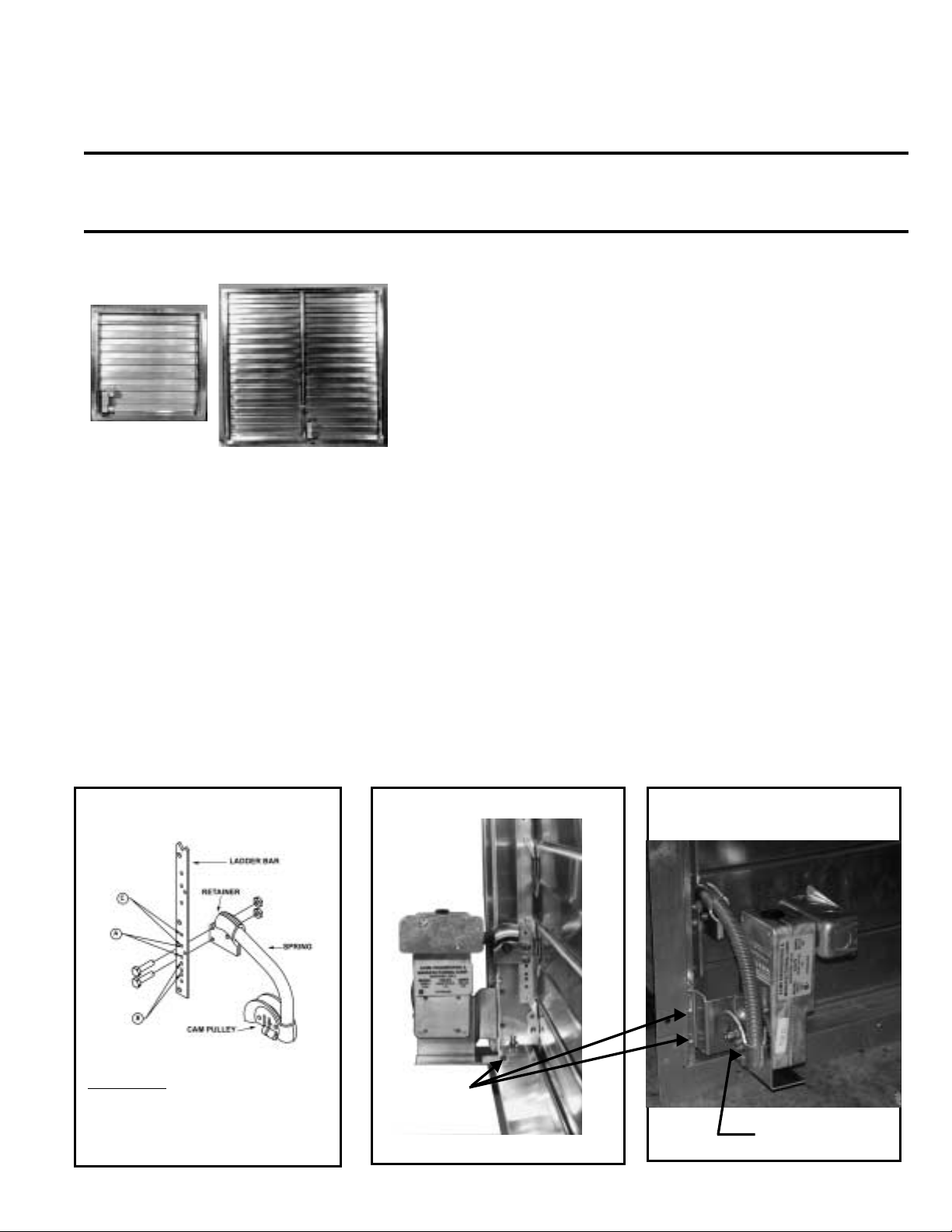
This CAM motor operation package consists of four major components;
motor with base, CAM assembly (with pull spring, CAM pulley and spring
retainer) and hardware. Follow steps in sequence for best results.
Make all electric connections using good wiring practices and in
accordance with National Electric Code and any local codes.
HINTS (A) On new installations, assembly of the motorizing kit would be
(B) DO NOT ATTACH THE CAM OPERATOR TO THE MOTOR
Single Panel Instructions
1. Refer to Chart 2 on page 5 for proper retainer hole location. Attach the pull spring retainer to the backdraft
damper ladder bar using two (2) bolts and lock nuts.
Opening the unit will give easy access to the ladder
bar.
2. Mount the motor and base using three (3) No. 8
screws (and three (3) speed nuts on aluminum
frames) by aligning the slots in the motor with the three
(3) holes in the frame. (Note: On some models the
backdraft damper frame is not pre-drilled. In this case,
use the motor base as a template to locate the proper
locations. For single panel units, the motor base
should fit in the lower left corner of the backdraft
damper as viewed from the inlet side. The motor base
Step 1 TOP VIEW
more easily done prior to installing the damper.
UNTIL THE CAM ASSEMBLY IS ATTACHED TO THE
BACKDRAFT DAMPER LADDER BAR AND THE MOTOR IS
ATTACHED TO THE BACKDRAFT DAMPER FRAME.
should be square to the backdraft damper. Self drilling
screws can be used to secure the motor base to the
backdraft damper frame. As an alternate to the self
drilling screws, .125" diameter holes can be pre-drilled
to use the #8 screws provided in the motor kit.
3. Attach the CAM pulley to the motor shaft. Position the
CAM assembly so that approximately 1/8" of the motor
shaft is showing through the CAM pulley, then tighten
the cam clamp bolt.
4. Check to see that all other bolts in the assembly are
tight.
IMPORTANT
ASSEMBLE IN THIS MANNER:
Bolt through ladder bar first, then
retainer, then lock nut.
Step 2
Step 3
Page 2
Backdraft Damper Double Panel Installation - WAGC & WAAC
Step 1
Refer to chart 1 for proper retainer hole location. Attach the pull
spring retainer to the backdraft damper ladder bar using two (2)
bolts and lock nuts. Opening the unit will give easy access to the
ladder bar.
CHART 1
MATCH RETAINER HOLE LOCATION TO BACKDRAFT
DAMPER MODEL SIZE BELOW
ABCC
4040 4141 4242
4343 4444 4545 4646
4747 4848 4949 5050
5151 5252 5353 5454
5555 5656 5757 5858
5959 6060 6161 6318
6363 6340 6565 6362
6767 6464 6969 6262
7171 6868 6666
7272 7070
IMPORTANT
ASSEMBLE IN THIS MANNER:
Bolt through the ladder bar first, then retainer, then lock
nuts.
Step 2
Mount the motor and base as shown using three (3) No. 8 screws (and three (3)
speed nuts onaluminum frames) by aligning the slots in the base with the three
(3) holes in the frame and center bar.
WAAC
WAAC With Light Shields
Step 3
Attach the CAM pulley to the
motor shaft. Position the CAM
assembly so that approximately
1/8" of the motor shaft is showing
through the CAM pulley then
tighten the Cam clamp bolt.
Page 2
Page 3

BACKDRAFT DAMPER INSTALLATION - WAGC, WAAC, WAA & WAG
C = Wide
D = High
MODEL
1212 12.00 12.00 9.75 10.32 1 1
1313 13.00 13.00 10.75 11.32 1 1
1414 14.00 14.00 11.75 12.32 1 1
1515 15.00 15.00 12.75 13.32 1 1
1616 16.00 16.00 13.75 14.32 1 1
1717 17.00 17.00 14.75 15.32 1 1
1818 18.00 18.00 15.75 16.32 1 1
1919 19.00 19.00 16.75 17.32 1 1
2020 20.00 20.00 17.75 18.32 1 1
2121 21.00 21.00 18.75 19.32 1 1
2222 22.00 22.00 19.75 20.32 1 1
2323 23.00 23.00 20.75 21.32 1 1
2424 24.00 24.00 21.75 22.32 1 1
2525 25.00 25.00 22.75 23.32 1 1
2626 26.00 26.00 23.75 24.32 1 1
2727 27.00 27.00 24.75 25.32 1 1
2828 28.00 28.00 25.75 26.32 1 1
2929 29.00 29.00 26.75 27.32 1 1
3030 30.00 30.00 27.75 28.32 1 1
3131 31.00 31.00 28.75 29.32 1 1
3232 32.00 32.00 29.75 30.32 1 1
3333 33.00 33.00 30.75 31.32 1 1
3434 34.00 34.00 31.75 32.32 1 1
3535 35.00 35.00 32.75 33.32 1 1
3636 36.00 36.00 33.75 34.32 1 1
3737 37.00 37.00 34.75 35.32 1 1
3838 38.00 38.00 35.75 36.32 1 1
3939 39.00 39.00 36.75 37.32 1 1
4040 40.00 40.00 37.75 38.32 2 1
4141 41.00 41.00 38.75 39.32 2 1
4242 42.00 42.00 39.75 40.32 2 1
4343 43.00 43.00 40.75 41.32 2 1
4444 44.00 44.00 41.75 42.32 2 1
4545 45.00 45.00 42.75 43.32 2 1
4646 46.00 46.00 43.75 44.32 2 1
4747 47.00 47.00 44.75 45.32 2 1
4848 48.00 48.00 45.75 46.32 2 1
4949 49.00 49.00 46.75 47.32 2 1
5050 50.00 50.00 47.75 48.32 2 1
5151 51.00 51.00 48.75 49.32 2 1
5252 52.00 52.00 49.75 50.32 2 1
5353 53.00 53.00 50.75 51.32 2 1
5454 54.00 54.00 51.75 52.32 2 1
5555 55.00 55.00 52.75 53.32 2 1
5656 56.00 56.00 53.75 54.32 2 1
5757 57.00 57.00 54.75 55.32 2 1
5858 58.00 58.00 55.75 56.32 2 1
5959 59.00 59.00 56.75 57.32 2 1
6060 60.00 60.00 57.75 58.32 2 1
6161 61.00 61.00 58.75 59.32 2 1
6262 62.00 62.00 59.75 60.32 2 1
6363 63.00 63.00 60.75 61.32 2 1
The framed opening can be calculated for backdraft damper sizes not shown. For units mounted outside the wall, subtract 3 inches from the width and height
dimension of thebackdraft damper. For units mounted through the wall, subtract 2.25 inchesfrom the width and subtract 1.68 inches from the height. Be sure the
bottom blade does not rub the framing.
A BCD
IN IN IN IN
Number of
Panels
Number of
Motors
Page 3
Page 4

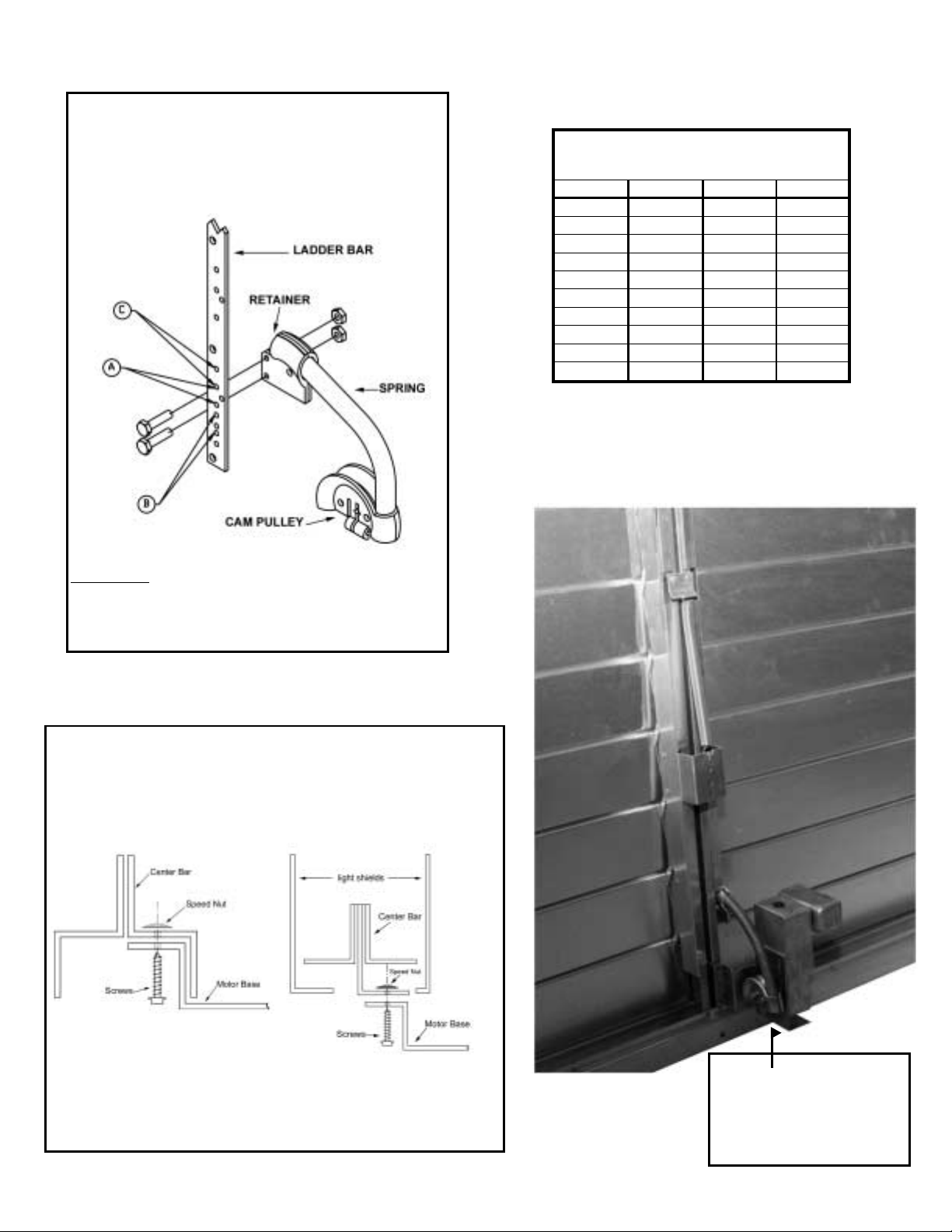
BACKDRAFT DAMPER DOUBLE PANEL INSTALLATION - WAG & WAA
Step 1
Refer to chart 2 for proper retainer hole location.
Attach the pull spring retainer to the backdraft
damper ladder bar using two (2) bolts and lock
nuts. Opening the backdraft damper will give
easy access to the ladder bar.
IMPORTANT
ASSEMBLE IN THIS MANNER:
Bolt through the ladder bar first, then retainer,
then lock nuts.
Step 4 (For Existing Installation)
Attach the panel connectinglink to
the two center ladder bars, at
holes provided, using four (4)
No. 8 x 5/8” bolts and lock nuts.
IMPORTANT
Assemble in this manner.
bolt through ladder bar
first, then panel link, then
lock nuts.
Step 2
Mount the motor and base as shown using three
(3) No. 8 screws (and three (3) speed nuts on
aluminum frames) by aligning the slots in the
base with the three (3) holes in the frame and
center bar.
Step 3
Attach the CAM pulley to the motor shaft.
Position the CAM assembly so that
approximately 1/8" of the motor shaft is
showing through the CAM pulley then tighten
the CAM clamp bolt.
NOTE: Return Spring is not required on this unit.
Page 4
Page 5

BACKDRAFT DAMPER - WAG & WAA
Preparing Backdraft Damper For Existing Installations
Mounting holes need to be provided to the motor base in the backdraft damper frame and center bar (double panel) and for the spring
retainer in the ladder bar.
1. USING THE MOTOR BASE AS A TEMPLATE.
A. On single panel units, drill (3) holes in the lower left hand corner of the backdraft damper frame:
B. On double panel units, drill (2) holes inthe centerbar onthe righthand leg and(1) holein thebackdraft damper
frame. Be sure to locate the motor base inside the channel of the center bar. (See step 2, Page 2)
2. Locate the backdraft damper size (outside dimensions) on the chart below and select the proper retainer hole lo
cations. Mark the ladder bar and drill (2) 11/16” holes.
3. Follow assembly instructions on page 1 (single panel) or page 2 (double panel) to complete the installation.
-
SINGLE PANEL
CHART 2
MATCH RETAINER HOLE LOCATION TO
BACKDRAFT DAMPER MODEL SIZE BELOW
AB C C
2 9/32” 1 1/4” 2 15/16 2 15/16
1212 1313 1414
1515 1616 1717 1818
1919 2020 2121 2222
2323 2424 2525 2626
2727 2828 2929 3030
3131 3232 3333 3434
3535 3636 3737 3838
3939 4040 4141 4242
4343 4444 4545 4646
4747 4848 4949 5050
5151 5252 5353 5454
5555 5656 5757 5858
5959 6060 6161 6318
6363 6340 6565 6362
6767 6464 6969 6262
7171 6868 6666
7272 7070
Sizes 12-39 are single panel units and the
remaining sizes are double panel units.
DOUBLE PANEL
Page 5
Page 6
ELECTRICAL CONNECTIONS
Make all electrical connections using good wiring practices
and in accordance with National Electric Code and any local
code.
When using this motor in a moist environment, incorporate a
drip loop in the wiring and/or conduit to prevent water from
tracking into the junction box.
When wiring is complete, caulk the wire passage from the
junction box into the motor. This will extend the life of the
motor.
WARNING
To prevent excessive gaps or binding between the
backdraft damper frame and the blades, the following
must be observed.
1. Backdraft Damper mounting frame surface must be
flat and parallel to the mounting surface of the unit.
2. Backdraft Damper sides, top and bottom must be
straight and parallel when mounted to the framed
mounting surface.
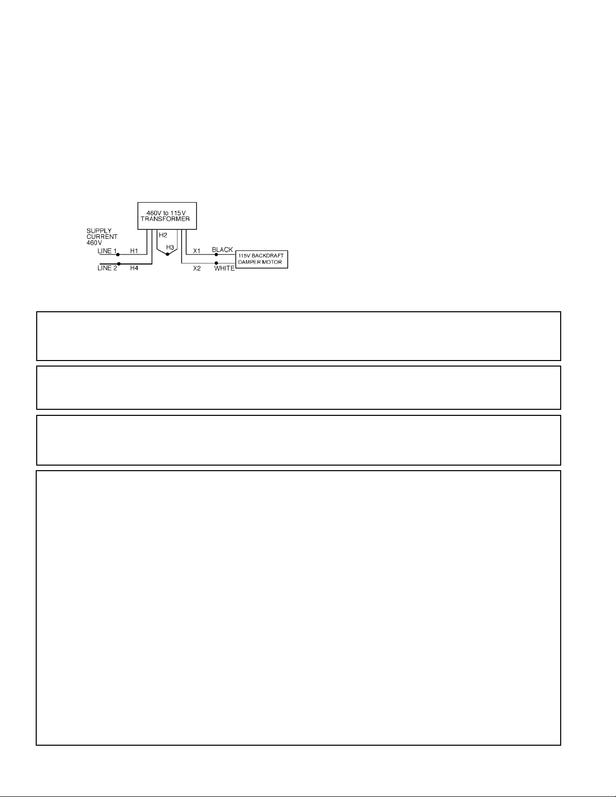
NOTE: If this motorizing kit is to be used in an application
requiring 460 volt single phase, a 115 volt backdraft
damper motor and a 460 volt to 15 volt transformer will
be supplied and must be wired as shown.
These instructions cover the usual installation, operation and maintenance methods for which the product(s) was designed. They do not purport to cover all details or
variations in the product(s) norto provide for everypossible contingency that might bemet in connection withthe installation, operation and maintenance.For any depar
tures from these instructions, or should particular problems arise which are not covered sufficiently for the purchaser’s purpose, the matter should be referred to the
Company.
The Company has made a diligent effort to illustrate and describe the products in this literature accurately; however such illustrations and descriptions are for the sole
purpose of identification and do not express or imply a warranty that the products are merchantable or fit for a particular purpose, or that the products will necessarily
conform to the illustrations or descriptions or dimensions.
The Companyproducts are designed and manufactured to provide reliable performance, but they are not guaranteed to be 100% freeof defects.Even reliableproducts
will experience occasional failures and this possibilityshould be recognized by the User.If theseproducts are used in a lifesupport ventilation support system where fail
ure could result in loss or injury, the user should provide adequate back-up ventilation, supplementarynatural ventilationor failurealarm system or acknowledge willing
ness to accept the risk of such loss or injury.
WARRANTY AND DISCLAIMER. The Company
extends this limited warranty to the original buyer
and warrants that products manufactured by the
Company shall be free from original defects in
workmanship and materials for two years fromdate
of shipment, provided same have been properly
stored, installed, serviced, maintained and oper
ated. This warranty shall not apply to products
which have been altered or repaired without the
Company’s express authorization, or altered or re
paired in any way so as in the Company’sjudgment
to affect its performance or reliability, nor which
have been improperly installed or subjected to mis
use, negligence or accident, or incorrectly used in
combination with other substances. The Buyer as
sumes all risks and liability for the results of use of
the products. Warranties on purchased parts such
as electric motors, pumps and controls are limited
to the terms of warranty extended by our supplier.
LIMITATION OF REMEDY AND DAMAGES. All
claims underthis warranty must be made in writing
and delivered to Box 978, Muskogee, Oklahoma
74402 within 15 days after discovery of the defect
and prior to the expiration of two years from the
date of shipment by the Company of the product
claimed defective, and Buyer shall be barred from
any remedy if Buyer fails to make such claim within
such period.
Within 30 days after receipt of a timely claim, the
Company shall have the option either to inspect the
product while in Buyer’s possession or to request
Buyer to return the product to the Company at
Buyer’s expense for inspection by the Company.
The Company shall replace, or at its option repair,
free of charge, any product it determines to be de
fective, and it shall ship the repaired or replacement
product to Buyer F.O.B., point of shipment pro
vided, however, if circumstances are such as in the
-
Company’s judgement to prohibit repair or replace
ment to remedy the warranted defects, the Buyer’s
sole and exclusive remedy shall be a refund to the
-
Buyer of any part of the invoice price, paid to the
Company for the defective product or part.
The Company is not responsible for the cost of re
moval ofthe defectiveproduct orpart damages due
to removal, or any expenses incurred in shipping
the product or part to or from the Company’s plant,
or the installation of the repaired or replaced prod
uct or part.
Implied warranties, when applicable, shall com
mence upon the same dateas the express warranty
provided above, and shall except for warranties of
title, extend only the duration of the express war
ranty. Some states do not allow limitations on how
long an implied warranty lasts, so the above limita
tion may not apply to you. The only remedy pro
vided to you under an applicable implied warranty
and the express warranty shall be the remedy pro
vided under the express warranty. Subject to the
terms and conditions contained therein, the Com
pany shall not be liable for incidental and conse
quential losses and damages under the express
warranty, any applicable implied warranty, or
claims for negligence, except to the extent that this
NOTICE
DISCLAIMER
WARNING
LIMITED WARRANTY
limitation is found to be unenforceable under ap
plicable state law. Some states do not allow the
-
exclusion or limitation of incidental or conse
quential damages, so the above limitation or ex
-
clusion maynot applyto you.This warranty gives
you specific legal rights, and you may also have
-
other rights which vary from state to state.
No employee, agent, dealer, or other person is
authorized to give any warranties on behalf of the
Company or to assume for the Company any
other liability in connection with any of its prod
-
ucts except in writing and signed by an officer of
the Company.
TECHNICAL ADVICE AND RECOMMENDA
TIONS, DISCLAIMER. Notwithstanding any
past practice or dealings or any custom of the
trade, sales shall not include the furnishing of
-
technical advice or assistance or system design.
Any such assistance shall be at the Company’s
sole option and may be subject to additional
-
charge.
The Company assumes no obligation or liability
on account of any recommendations, opinions or
advice as to the choice, installation or use of
products. Any such recommendations, opinions
or advice are given and shall be accepted atyour
own risk and shall not constitute any warranty or
guarantee of such products ortheir performance.
GENERAL. In no event shallany claim for conse
quential damages be made by either party. The
Company will comply with all applicable Federal,
State and local laws.
Page 6 December 2000 Form 613120
-
-
-
-
-
-
-
-
-
 Loading...