

Page 1

FORM 613095
Read and Save These Instructions
INSTALLATION & MAINTENANCE INSTRUCTIONS
Models XB, XD, USB and USD
RECEIVING AND INSPECTION
humidity indicators at several points and maintain the
atmosphere at 40% relative humidity, or lower.
Immediately upon receipt of a shipment, carefully inspect for
damage and shortage. Turn the impeller by hand to see that it
turns freely and does not bind. If any damage and/or shortage
is detected or suspected, the carrier must be asked to
conduct an inspection. The consignee’s representative should
not accept a shipment without a notation on the delivery
receipt indicating items not delivered or the apparent extent of
damage.
When a shipment is opened and damage is found which was
not evident externally (concealed damage), it is mandatory
that the consignee request an immediate inspection by the
carrier. Report any damage to the carrier within 15 days.
Failure to report damage within the above time limit will result
in rejection of a claim.
HANDLING
When handling fans and their accessories, always use
equipment and methods that will not cause damage. Fans
should be lifted using slings and padding or spreaders to
avoid damage.
CAUTION! Always make sure that all lifting and handling
equipment and techniques conform to current safety
standards.
Avoid lifting fans in a way that will bend or distort fan parts.
Never pass slings or timbers through the orifices of fan.
CAUTION! Do not lift by the fan hood. Fans with special
coatings or paints must be protected in handling to prevent
damage.
STORAGE
Fans are protected against damage during shipment. If they
cannot be installed and put into operation immediately upon
receipt certain precautions are necessary to prevent
deterioration during storage. Responsibility for integrity of
fans and accessories during storage must be assumed by the
user. The manufacturer will not be responsible for damage
during storage. These suggestions are provided solely as a
convenience to the user, who shall make his own decision as
to whether to use any or all of them.
INDOOR: The ideal storage environment for fans and
accessories is indoors, above grade, in a low humidity
atmosphere which is sealed to prevent the entry of blowing
dust, rain, or snow. Temperatures should be evenly
maintained at between 70°F and 105°F (wide temperature
swings may cause condensation and "sweating" of metal
parts). Windows should be covered to prevent temperature
variations caused by sunlight. Provide thermometers and
It may be necessary to use trays of renewable desiccant or
portable dehumidifier to remove moisture from the air in the
storage enclosure.
Thermostatically controlled portable heaters (vented to
outdoors) may be required to maintain even temperatures
inside the enclosure.
CAUTION! Provide fire extinguishers, or fire alarms, or
emergency response communication to protect building and
equipment against fire damage. Be sure that building and
storage practices meet all local, state and federal fire and
safety codes.
The following fans or accessories must be stored indoors, in
a clean dry atmosphere:
a. Propeller wall fans not in wall housings.
b. Any fan protected by a cardboard carton.
c. Motors dismounted from fans.
d. Spare wheels or propellers.
e. Belts, sheaves, bushings and other parts when not
mounted on fan.
f. Boxes, bags or cartons of hardware.
g. Curbs
h. Dampers
Remove any accumulations of dirt, water, ice or snow and
wipe dry before moving indoor storage. Allow cold parts to
reach room temperature to avoid “sweating” of metal parts.
Open boxes or cartons. Remove any accumulated moisture;
if necessary use portable electric heaters to dry parts and
packages. Leave coverings loose to permit air circulation and
to permit periodic inspection.
Rotate wheels or propellers by hand to distribute bearing
grease over the entire bearing surfaces.
Store at least 3 ½” off the floor on wooden blocks covered
with moisture proof paper or polyethylene sheathing. Provide
aisles between parts and along all walls, to permit air
circulation and space for inspection.
OUTDOOR: Fans designed for outdoor use may be stored
outdoors, if absolutely necessary. The storage area should
be reasonably level and drained or ditched to prevent
accumulation of water. Fencing and lighting for security are
desirable. Roads or aisles for portable cranes and hauling
equipment are needed. Consider the use of drift fencing to
minimize accumulation of blowing snow or dirt.
The following fans may be stored outdoors, if dry indoor
storage space is not available:
a. Fans intended for outdoor use that are crated in wood.
b. Wall fans installed in wall housings.
Page 2
All fans must be supported on wooden blocks or timbers
above water or normal snow levels. Provide enough blocking
to prevent settling into soft ground. Fans should be set in
place using the directional arrow markings on the crate as a
guide.
Locate pieces far enough apart to permit air circulation,
sunlight, and space for periodic inspection. Place all parts on
their supports so that rain water will run off, or to minimize
water accumulation. Do not cover parts with plastic film or
tarps - these cause condensation of moisture from the air
passing through heating and cooling cycles.
Fan wheels and propellers should be blocked to prevent
spinning caused by strong winds.
INSPECTION AND MAINTENANCE DURING STORAGE
Inspect fans and accessories at least once per month, while
in storage. Log results of inspection and maintenance
performed. A typical log entry should include the following:
a. Date
b. Inspector’s Name
c. Name of Fan
d. Location
e. Condition of Paint or Coating
f. Is moisture present?
g. Is dirt accumulated?
h. Corrective steps taken?
If moisture or dirt accumulations are found on parts, the
source should be located and eliminated. Fans should be
rotated at each inspection by hand ten to fifteen revolutions to
redistribute the motor and bearing lubricant.
If paint deterioration begins, consideration should be given to
touch-up or repainting. Fans with special coatings may
require special techniques for touch-up or repair.
Machined parts coated with rust preventive should be
restored to good condition promptly if signs of rust occur. The
most critical items are pulleys, shafts and bearing locking
collars. At the first sign of rusting on any of the above parts,
remove the original rust preventive coating with petroleum
solvent and clean lint-free cloths. Polish any remaining rust
from surfaces with crocus cloth or fine emery paper and oil.
Do not destroy the continuity of the surfaces. Wipe clean
with lint-free cloths and recoat surfaces evenly and thoroughly
with Tectly 506 (Ashland Oil Company) or equal. For hard to
reach internal surfaces or for occasional use, consider using
Tectly 511M Rust Preventive or WD40 or equal.
2. WARNING! Do not use in hazardous environments where
the fan’s electrical system could provide ignition to
combustible or flammable materials, unless the unit is
specifically built for hazardous environments.
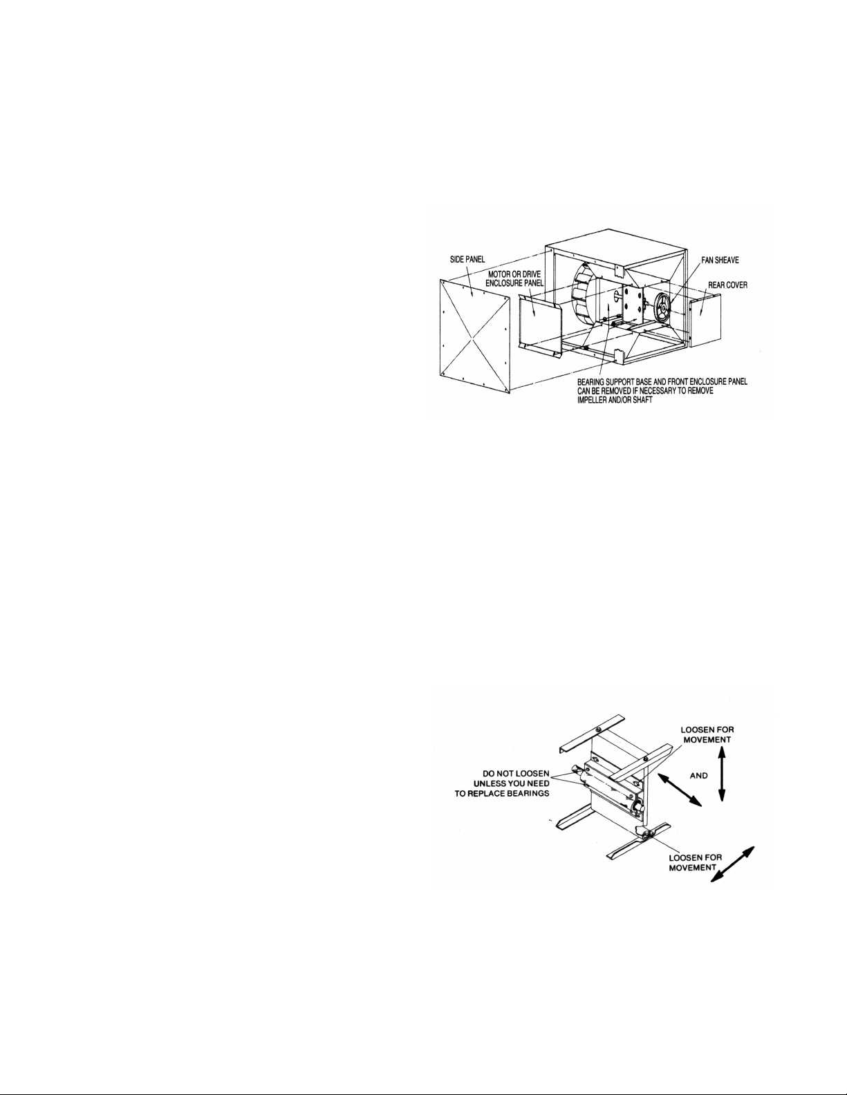
3. Impeller Adjustment: Turn centrifugal impeller by hand to
make sure it rotates freely. If impeller hits orifice, remove
side panel (both sides are removable) and motor or drive
enclosure panel as in shown Figure1.
Figure 1
Adjustment is made as follows:
4.
Direct Driven Units
Loosen bolts holding the motor to the mounting frame.
This will allow free movement of the impeller in all
directions for adjustment. Do not loosen the set screws in
the impeller hub since this will only allow movement in or
out on the motor shaft. Tighten all bolts before operating
the unit.
Belt Driven Unit
The bearing support base and the bearing lower housing
are slotted for adjustment. Loosen the bolts indicated in
Figure 2 and center the impeller over the orifice. Tighten
all bolts before operating the unit.
REMOVING FROM STORAGE
As fans are removed from storage to be installed in their final
location, they should be protected and maintained in similar
fashion, until the fan equipment goes into operation.
INSTALLATION
1. These units are not air tight and should not be used where
escape of contaminated air would cause problems.
CAUTION! This unit has rotating parts and safety
precautions should be exercised during installation,
operation and maintenance.
Page 2
Figure 2
Belt drive units are shipped without the sheaves mounted.
5.
Remove the sheaves from the drive package and install
on the fan. The rear cover is removable if required.
6. Check the pulley alignment and belt tension. Adjust the
belt tension using motor base jack screws. Belt should
depress its width when pressed firmly inward at midway
point between the pulleys. Replace all panels and tighten
corresponding bolts.
Page 3

7. If unit is to be equipped with isolators and/or support
brackets they should be attached at this time using the
mounting instructions (Form 613101) included with them.
8. Securely support the unit and attach the duct work.
9. Units used outdoors should be installed to provide
maximum weather protection. Direct driven units should
be positioned so that the breather tube to the motor
compartment will not let moisture enter. Belt driven units
should include a motor cover to protect the motor and belt
enclosure opening from moisture.
10. CAUTION! Before proceeding, make sure electrical
service to the fan is locked in the “OFF” position.
11. All wiring should be in accordance with local ordinances
and the National Electric Code.
12. WARNING! Check the voltage at the fan to see if it
corresponds with the motor nameplate. High or low
voltage can seriously damage the motor. Extra care
should be taken when wiring two speed motors since
improper connections will damage the motor and void the
motor warranty. On belt driven units, leave enough slack
in wiring to allow for motor movement when adjusting belt
tension.
13. Apply power momentarily and compare the rotation of the
impeller with the directional arrow on fan. WARNING!
Operation in the wrong direction will deliver air but will
overload the motor to the extent of blowing fuses and
seriously damaging the motor. In the case of three phase
motors, the direction can be changed by interchanging
any two of the three motor leads. In the case of single
phase motors, the reversing instructions will appear on the
wiring diagram in the motor wiring compartment.
14. CAUTION! Guards must be installed when the fan is
within reach of personnel or within eight (8) feet (2.5m) of
working level or when deemed advisable for safety.
MAINTENANCE
1. Under normal usage, no spare parts are recommended for
one year of operation. Recommended spare parts are
shown on Pages 6 and 7.
2. CAUTION! Before proceeding, make sure electrical
service to the fan is locked in the “OFF” position.
WINDMILLING: Even when the power supply is locked
out, fans may cause injury or damage if the impeller is
subject to “windmilling” which is the turning of the impeller
and drive components due to a draft in the system. To
guard against this hazard, the impeller should be secured
to physically restrict rotational movement.
3. Acme Duplex Split pillow block bearings are prelubricated
and do not require relubrication. Units with pillow block
bearings have grease fittings and, under normal operating
conditions, will need no relubrication for 3 to 5 years. If
relubrication is required, use a grease conforming to NLGI
No. 2. CAUTION! Lubricating bearings with a high
pressure gun can blow bearing seals and overfill the
bearing with grease. This condition can result in excessive
churning and overheating. For normal operating conditions
it is standard practice to fill only 30% of the bearing void
with grease. Do not over lubricate.
4. Motor bearings are prelubricated. Consult information
printed on the motor for lubrication instructions.
5. On belt driven units, check belt tension after the first 48
hours of operation and thereafter annually. Belt should
depress its width when pressed firmly inward at midway
point between the pulleys. Too much tension will damage
the bearings. The belt should be tight enough to prevent
slippage. When replacing a worn belt, replace the motor
pulley if “shoulder” is worn in groove. WARNING! Do not
replace the motor pulley with a larger diameter pulley. Do
not replace the fan pulley with one smaller in diameter.
The pulley ratios are set so that the motor will not be
overloaded. Do not operate at higher speeds than that
cataloged for this equipment.
6. If it should become necessary to remove the impeller, first
remove the motor and impeller or shaft, bearing and
impeller assembly.(See Figure 1) On model sizes 120,
137 and 161 there is a sleeve which fits inside the impeller
hub. To remove the impeller from the shaft, completely
remove the two socket head cap screws that go through
the sleeve. The impeller will then slide off the sleeve and
the set screws attaching the sleeve can be loosened
allowing its removal. The impellers on larger size units are
attached with a roll pin. Remove the roll pin by driving it
out with a drift pin.
7. On belt driven units: If impeller shaft bearings need
replacement, replace with bearing comparable to the
original equipment. If Acme Duplex Split pillow block
bearings are used, install new bearings into neoprene
rings, check correct position of impellers with orifice,
position bearings in the die-formed recess and tighten the
set screws. Replace the die-formed bearing cap and
tighten the four bolts.
NOTE: If locking collar type bearing is used, collar must
first be positioned against the inner race on the bearing
nearest the impeller and turned in the direction of impeller
rotation with a drift pin and hammer until it locks. Locking
collars must be on the inboard (facing) sides of the
bearings. Secure the bearing to the shaft with set screws.
Lock and secure the other bearing to the shaft in the same
manner.
NOTE: If pillow block type bearings are used, slide
bearings onto shaft to desired location and bolt bearing
block securely to support base. Slide shaft back and forth
in secured bearing (do not drive with hammer) and rotate
to make certain it turns freely. Check correct position of
propeller with inlet orifice. Then secure bearings to shaft
by tightening set screws.
Page 3
Page 4

SET SCREW TIGHTENING SCHEDULE
1. Before initial operation of the fan, tighten set screws
according to the procedure outlined below.
2. After 500 operating hours or three months, whichever
comes first, tighten set screws to the full recommended
torque.
PROCEDURE FOR TIGHTENING SET SCREWS IN
BEARINGS AND HUBS
One Set Screw Application
Using a torque wrench, tighten the set screw to the torque
recommended in Table 1.
3. At least once a year, tighten set screws to the full
recommended torque.
Table 1. Recommended Tightening
Torque for Set Screws
Set Screw Diameter Torque (in-lbs)
#10 35
1/4 80
5/16 126
3/8 240
7/16 384
1/2 744
9/16 1080
5/8 1500
3/4 2580
7/8 3600
1 5400
Two Set Screw Application
1. Using a torque wrench, tighten one set screw to half of the
torque recommended in Table 1.
2. Tighten the second set screw to the full recommended
torque.
3. Tighten the first set screw to the full recommended torque.
VARIABLE FREQUENCY
DRIVES AND MOTORS
There are occasions when a Variable Frequency Drive (VFD)
will cause poor motor performance and possible damage. To
avoid these problems, the Company recommends the
following:
1. Select compatible motor and VFD inverter; if possible, the
motor and the inverter should be from the same
manufacturer or at least the inverter selected should be
recommended by the motor manufacturer.
2. A motor shaft grounding system should be used to prevent
motor bearing damage from eddy currents.
NOTE: The Company will not honor motor warranty
claims if the customer fails to follow these recommendations.
Wiring Diagram for EC Motors
When XD fans are used with EC Motors and the optional remote speed control, the following wiring diagram should be
observed. A 120/24 VAC transformer will be added to the fan assembly for the purpose of powering the logic circuits in both
the motor and the remote speed control. The remote speed control will output a DC signal that varies from 0 to 10V. This
signal will vary the motor speed. All 120V connections will be made in the supplied junction box. Wire to the remote speed
control is to be supplied by others and must meet all applicable codes. The remote speed control location is limited by a
maximum wire length of 100 feet. Up to 6 fans can be operated from one remote control. Only one transformer should be
used. The 0-10 VDC (red) wires should be connected together, the common (white) wires should be connected together, and
the 24 VAC (black) should be connected together.
To use the remote variable speed control the speed control on the motor (if present) should be set full clockwise.
Page 4
Page 5

BELT DRIVE CENTRIFUGAL INLINE FAN RPM SELECTION TABLE
Model
Size
Power
HP 0
1
2
Fan RPM vs. Number of Turns from Full Closed
11
1
2
22
1
2
33
1
2
44
1
2
5
090E1 .25 2177 2118 2058 1999 1939 1880 1821 1761 1702 1642 1583
090E2 .25 2492 2428 2363 2299 2234 2170 2105 2041 1976 1912 1847
090F .33 2717 2637 2558 2478 2398 2319 2239 2159 2079 2000 1920
090G .50 3196 3110 3023 2937 2851 2765 2678 2592 2506 2419 2333
120E1 .25 1375 1317 1259 1201 1143 1084 1026 968 910 —— ——
120E2 .25 1570 1520 1470 1420 1370 1320 1270 1220 1170 1120 1070
120F .33 1725 1667 1608 1550 1491 1433 1374 1316 1257 1199 1140
120G .50 2060 1994 1928 1862 1796 1730 1664 1598 1532 1466 1400
120H .75 2335 2261 2186 2112 2037 1963 1888 1814 1739 1665 1590
120J 1.00 2570 2507 2443 2380 2316 2253 2189 2126 2062 1999 1935
137F .33 1365 1322 1278 1235 1191 1148 1104 1061 1017 974 930
137G .50 1605 1551 1496 1442 1387 1333 1278 1224 1169 1115 1060
137H .75 1830 1780 1729 1679 1628 1578 1527 1477 1426 1376 1325
137J 1.00 2060 1994 1928 1862 1796 1730 1664 1598 1532 1466 1400
137K 1.50 2310 2247 2183 2120 2056 1993 1929 1866 1802 1739 1675
137L 2.00 2490 2437 2383 2330 2276 2223 2169 2116 2062 2009 1955
161F .33 1055 1019 983 947 911 875 839 803 767 731 695
161G .50 1210 1172 1133 1095 1056 1018 979 941 902 864 825
161H .75 1365 1322 1278 1235 1191 1148 1104 1061 1017 974 930
161J 1.00 1570 1520 1470 1420 1370 1320 1270 1220 1170 1120 1070
161K 1.50 1710 1672 1634 1596 1558 1520 1482 1444 1406 1368 1330
161L 2.00 1865 1819 1773 1727 1681 1635 1589 1543 1497 1451 1405
161M 3.00 2210 2163 2115 2068 2020 1973 1925 1878 1830 1783 1735
200H .75 985 954 922 891 859 828 796 765 733 702 670
200J 1.00 1055 1023 990 958 925 893 860 828 795 763 730
200K 1.50 1250 1211 1172 1133 1094 1055 1016 977 938 899 860
200L 2.00 1410 1371 1332 1293 1254 1215 1176 1137 1098 1059 1020
200M 3.00 1525 1492 1459 1426 1393 1360 1327 1294 1261 1228 1195
200N 5.00 1885 1854 1822 1791 1759 1728 1696 1665 1633 1602 1570
245H .75 645 625 604 584 563 543 522 502 481 461 440
245J 1.00 735 712 688 665 641 618 594 571 547 524 500
245K 1.50 855 829 802 776 749 723 696 670 643 617 590
245L 2.00 965 935 905 875 845 815 785 755 725 695 665
245M 3.00 1100 1076 1052 1028 1004 980 956 932 908 884 860
245N 5.00 1295 1271 1246 1222 1197 1173 1148 1124 1099 1075 1050
300J 1.00 520 504 487 471 454 438 421 405 388 372 355
300K 1.50 595 577 558 540 521 503 484 466 447 429 410
300L 2.00 670 652 633 615 596 578 559 541 522 504 485
300M 3.00 775 759 742 726 709 693 676 660 643 627 610
300N 5.00 875 859 842 826 809 793 776 760 743 727 710
300P 7.50 1010 992 973 955 936 918 899 881 862 844 825
300R 10.00 1135 1114 1093 1072 1051 1030 1009 988 967 946 925
365K 1.50 450 436 422 408 394 380 366 352 338 324 310
365L 2.00 505 491 477 463 449 435 421 407 393 379 365
365M 3.00 555 543 531 519 507 495 483 471 459 447 435
365N 5.00 675 663 650 638 625 613 600 588 575 563 550
365P 7.50 760 746 732 718 704 690 676 662 648 634 620
365R 10.00 815 803 790 778 766 754 741 729 717 705 692
425K 1.50 380 369 359 348 338 328 318 307 296 285 255
425L 2.00 415 403 391 379 368 356 345 333 322 310 300
425M 3.00 475 463 451 439 427 415 403 391 379 367 355
425N 5.00 565 553 541 529 517 505 493 481 469 457 445
425P 7.50 645 633 621 609 597 585 573 561 549 537 525
425R 10.00 690 675 660 646 631 617 602 588 573 559 545
Actual speeds may vary as much as ±5%. Based on motor RPM of 1725.
Page 5
Page 6

Belt Drive
17
18
19
20
21
22
23
24
25
26
27
28
1
2
3
4
5
6
7
9
10
11
12
13
14
15
16
8
No. Description Qty. No. Description Qty.
1 Motor Cover 1 15 Shaft and Bearing Assembly* 1
2 Disconnect Switch 1 16 Bearing Compartment Bottom 1
3 Motor Base 1 17 Bottom Panel 1
4 Motor Base Rails 2 18 Motor Compartment Back 1
5 Motor Rail Supports 2 19 Outlet Frame 1
6 Motor Support Brackets 2 20 Fan Sheave* 1
7 Impeller* 1 21 Bearing Base 1
8 Bearing Compartment Top 1 22 Rain Shield 1
9 Inlet Orifice 1 23 Bearing Compartment Top 1
10 Bearing Compartment Front 1 24 Belt Tube 1
11 Side Panels 4 25 Top Panel 1
12 Access Panels 2 26 Belt* 1
13 Bearing Compartment Side 2 27 Motor Sheave* 1
14 Bearing Cap 1 28 Motor* 1
*Recommended spare parts.
PARTS LIST LEGEND
Page 6
Page 7

Direct Drive
1
2
3
4
5
6
7
8
9
10
11
12
13
14
15
16
17
No. Description Qty. No. Description Qty.
1 Motor Base 1 10 Motor Compartment Front 1
2 Motor* 1 11 Access Panels 2
3 Breather Tube 1 12 Side Panels 4
4 Wiring Post 1 13 Motor Compartment Side 2
5 Disconnect Switch 1 14 Bottom Panel 1
6 Top Panel 1 15 Motor Compartment Bottom 1
7 Motor Compartment Top 1 16 Outlet Frame 1
8 Impeller* 1 17 Motor Compartment Back 1
9 Inlet Orifice 1
*Recommended spare parts.
PARTS LIST LEGEND
Page 7
Page 8

ACCEPTANCE All orders and sales are subject to
written approval and acceptance by an executive offi
cer of the Company at Muskogee, Oklahoma, and are
not binding on the Company until so approved.
DELIVERY All shipping and delivery dates are esti
mated only. No delays in delivery will subject the
Company to any costs, damages or fees for late deliv
ery. Delivery of the products herein specified shall be
made F.O.B. point of shipment, unless otherwise
stated. The Company shall not be liable for delay due
to causes beyond its reasonable control, such as Acts
of God, acts of the purchaser, acts of civil or military
authorities, priorities, fires, strikes, floods, epidemics,
war, riots, delays in transportation, car shortages, and
inability, due to reasons beyond its reasonable control,
to obtain necessary labor, material, or manufacturing
facilities. In the event of such a delay, the date of deliv
ery shall be extended for a period equal to the time lost
by reason of the delay.
TERMS OF PAYMENT If, in the judgment of the Com
pany, the financial condition of the purchaser at any
time does not justify continuation of manufacture or
shipment on the terms of payment specified, the Com
pany may require full or partial payment in advance.
Pro rata payments shall become due as shipments are
made. Each shipment or delivery shall constitute a
separate sale, and the default of any shipment or deliv
ery shall constitute a separate sale, and the default of
any shipment or delivery shall not vitiate the contract
as to other shipments or deliveries.
SALES AND SIMILAR TAXES The Company’s prices
do not include sales, use, excise, or similar taxes.
Consequently, in addition to the price specified herein,
the amount of any present or future sales, use, excise,
or other similar tax applicable to the sale of the product
herein shall be paid by the Purchaser, or in lieu thereof
TERMS AND CONDITIONS OF SALE
the Purchaser shall provide the Company with a tax
exemption certificate acceptable to the taxing authori
ties.
CANCELLATION Any contract resulting from the Pur
chaser’s order may be canceled by the Purchaser only
by negotiations and upon payments of reasonable can
cellation charges which will take into account expenses
already incurred and commitments made by the Com
pany.
DESIGN CHANGES The Company reserves the right
to make changes in design, improvements and addi
tions in and to its products any time without imposing
any liability or obligations to itself to apply or install the
same in any product manufactured by it.
TITLE The title and right of possession of the products
-
sold herein shall remain with the Company and such
products shall remain personal property until all
payments herein (including deferred payments whether
evidenced by notes or otherwise) shall have been
made in full in cash and the Purchaser agrees to do all
acts necessary to perfect and maintain such right and
title in the Company.
PRICE ADJUSTMENTS Prices are subject to change
upon notice by the Company. Prices on existing or
ders are subject to surcharges in the event of cost in
creases of metals and transportation. All complete
-
component accessory material manufactured by others
and furnished with the Company’s products such as
motors, drives, vibration equipment, controls or other
completely assembled component structures, are sub
ject to adjustment to the price at time of shipment re
gardless of the date of original order entry.
SAFETY ACCESSORIES The Company manufactures
products designed to serve multiple applications and
offers a wide range of safety equipment, including
guards and other devices, as may be required to meet
customer specifications. Without exception, the Com
pany recommends that all orders include applicable
safety devices. Products ordered without applicable
safety devices is clearly the responsibility of the Pur
chaser. Further, the Purchaser warrants that it has de
termined and acquired any and all safety devices re
quired for products sold by the Company. Weather
covers and guards for motor and V-belt drives, cou
plings, shafts and bearings, along with inlet and outlet
screens, are optional accessories noted in the price
list.
GOVERNING LAW The rights, obligations and reme
dies of Purchaser and the Company, the interpretation
of these terms and conditions and the sale of products
by the Company shall be governed by Oklahoma law,
without regard to any principles of conflict of laws.
ARBITRATION Any dispute arising under or in con
nection with these terms and conditions or the sale of
products shall be settled by binding arbitration admin
istered by the American Arbitration Association under
its Commercial Arbitration Rules, and judgment on the
award rendered by the arbitrator may be entered in
any court having jurisdiction thereof. The dispute shall
-
be resolved by one neutral arbitrator who shall have no
-
affiliation with either Purchaser or the Company and
shall be selected by the American Arbitration Associa
tion office in Dallas, Texas. The arbitration proceed
ings shall be held in Muskogee, Oklahoma.
APPLICABLE DOCUMENTS The agreement be
tween the Company and the Purchaser relating to the
products includes these terms and conditions of sale,
any applicable installation and maintenance instruc
tions provided by the Company and any terms appear
ing on the Company’s quotation, sales order acknowl
edgment and invoice.
-
-
-
-
-
-
-
-
-
-
-
-
-
-
WARNING The Company products are designed and manufactured to provide reliable performance but they are not guaranteed to be 100% free of defects. Even reliable prod
ucts will experience occasional failures and this possibility should be recognized by the Purchaser and all End Users. If these products are used in a life support ventilation sys
tem where failure could result in loss or injury, the Purchaser and all End Users should provide adequate back-up ventilation, supplementary natural ventilation or failure alarm
system, or acknowledge willingness to accept the risk of such loss or injury.
WARNING DO NOT use in HAZARDOUS ENVIRONMENTS where fan’s electrical system could provide ignition to combustible or flammable materials unless unit is specifically built for hazardous environments. Comply with all local and national safety codes including the National Electrical Code (NEC) and National Fire Protection Act (NFPA).
CAUTION Guards must be installed when fan is within reach of personnel or within eight (8) feet (2.5 m) of working level or when deemed advisable for safety.
DISCLAIMER The Company has made a diligent effort to illustrate and describe the products accurately in all Company literature; however such illustrations and descriptions
are for the sole purpose of identification and do not express or imply any warranty.
LIMITED WARRANTY
WARRANTY AND DISCLAIMER: the Company ex-
tends this limited warranty to the original purchaser
and warrants that products supplied by the Company,
shall be free from original defects in workmanship and
materials for two years from date of shipment (except
for the warranty periods noted for products listed be
low), provided same have been properly handled,
stored, installed, serviced, maintained and operated.
This warranty shall not apply to products which have
been altered or repaired without the Company’s ex
press authorization, or altered or repaired in any way
so as, in the Company’s judgment, to affect its perfor
mance or reliability, nor which have been improperly
installed or subjected to misuse, negligence, or acci
dent, or incorrectly used in combination with other sub
stances. The Purchaser assumes all risks and liability
for results of use of all products.
Evaporative cooling pads are warranted to be free of
defects in materials and workmanship for a period of
two years from date of shipment provided same have
been properly handled, stored, installed, serviced,
maintained and operated; and further, not subjected to
excessive heat, corrosive agents or chemicals, or me
chanical abuse that may cause tearing, crushing or un
due deterioration, nor used on a system or in a manner
other than that for which it was designed as explained
in the product literature.
The following products are warranted to be free of de
fects in materials and workmanship for the periods
shown from date of shipment: the Company’s exclu
sive duplex split pillow block bearings and shaft five
years, belts one year, Polyethylene tubing 90 days,
AIR40 Heater warranty one year, AIR40 Emitter war
ranty three years and DDP fan lifetime warranty on its
propeller, cone, and housing.
LIMITATION OF REMEDY AND DAMAGES: All
claims under this warranty must be made in writing and
delivered to P. O. Box 978, Muskogee, Oklahoma,
74402, within 15 days after discovery of the defect and
prior to the expiration of two years from the date of
shipment by the Company of the product claimed de
fective, and Purchaser shall be barred from any
remedy if Purchaser fails to make such claim within
such period.
Within 30 days after receipt of a timely claim, the Com
pany shall have the option either to inspect the product
while in Purchaser's possession or to request Pur
chaser to return the product to the Company at Pur
chaser's expense for inspection by the Company. The
Company shall replace, or at its option repair, free of
charge, any product it determines to be defective, and
it shall ship the repaired or replacement product to
Purchaser F.O.B. point of shipment; provided, how
-
ever, if circumstances are such as in the Company’s
judgment to prohibit repair or replacement to remedy
the warranted defects, the Purchaser's sole and exclu
sive remedy shall be a refund to the Purchaser of any
-
part of the invoice price, paid to the Company, for the
defective product or part.
The Company is not responsible for the cost of re
-
moval of the defective product or part, damages due to
-
removal, or any expenses incurred in shipping the
product or part to or from the Company’s plant, or the
installation of the repaired or replaced product or part.
The warranties set forth above do not apply to any
components, accessories, parts or attachments manu
factured by other manufacturers; such being subject to
the manufacturer’s warranty, if any. To the extent not
prohibited by the manufacturer’s warranty, the Com
-
pany shall pass through to Purchaser such manufac
-
turer’s warranty.
THE COMPANY’S WARRANTY IS IN LIEU OF ALL
OTHER WARRANTIES, EXPRESS OR IMPLIED,
ARISING BY LAW OR OTHERWISE, INCLUDING
WITHOUT LIMITATION THE IMPLIED WARRANTIES
OF MERCHANTABILITY AND FITNESS FOR A PAR
TICULAR PURPOSE, WHICH ARE HEREBY EX
PRESSLY DISCLAIMED AND WAIVED. THIS WAR
RANTY CONSTITUTES THE COMPANY’S SOLE
AND EXCLUSIVE WARRANTY FOR DEFECTIVE
GOODS AND PURCHASER’S SOLE AND EXCLU
SIVE REMEDY FOR DEFECTIVE PRODUCTS.
No employee, agent, dealer, or other person is autho
rized to give any warranties on behalf of the Company
or to assume for the Company any other liability in
connection with any of its products except in writing
and signed by an officer of the Company.
-
REPLACEMENT PARTS If replacement parts are or
dered, purchaser warrants that the original compo
nents in which these replacement parts will be placed
-
are in satisfactory working condition, and when said re
placement parts are installed, the resultant installation
-
will operate in a safe manner, at speeds and tempera
-
tures for which the original product was purchased.
TECHNICAL ADVICE AND RECOMMENDATIONS,
DISCLAIMER: Notwithstanding any past practice or
dealings or any custom of the trade, sales shall not in
clude the furnishing of technical advice or assistance
-
or system design. Any such assistance shall be at the
Company’s sole option and may be subject to addi
tional charge.
The Company assumes no obligation or liability on ac
count of any recommendations, opinions or advice as
to the choice, installation or use of products. Any such
recommendations, opinions or advice are given and
shall be accepted at Purchaser's and End User's risk
and shall not constitute any warranty or guarantee of
such products or their performance.
LIMITATION OF LIABILITY The cumulative liability of
the Company to the Purchaser and any other persons
for all claims in any way relating to or arising out of the
products, including, but not limited to, any cause of ac
tion sounding in contract, tort, or strict liability, shall not
exceed the total amount of the purchase price paid for
those products which are the subject of any such
claim. This limitation of liability is intended to apply
without regard to whether other provisions of this
agreement have been breached or have proven inef
fective even if the Company has been advised of the
possibility of such claims or demands. In no event
shall the Company be liable to the Purchaser or any
other person for any loss of profits or any incidental,
special, exemplary, or consequential damages for any
claims or demands brought by the Purchaser or such
other persons.
INDEMNITY The Company’s maximum liability to Pur
chaser and to any end user is as set forth above. The
Company makes no warranty to anyone for any prod
ucts not manufactured by the Company and shall have
no liability for any use or installation of any products
(whether manufactured by the Company or other man
ufacturers) not specifically authorized by this sale.
Purchaser acknowledges various warnings by the
Company regarding the products and its installation
-
and use. If the Company incurs any claims, lawsuits,
-
settlements, or expenses (including attorney fees) for
any loss, injury, death or property damage including,
-
but not limited to, claims arising out of the Purchaser’s
or any end user’s installation or use of the products,
-
the Purchaser shall indemnify and hold the Company
harmless.
-
-
-
-
-
-
-
-
-
-
November 2012 613095
 Loading...