

Page 1
FORM 613097
Read and Save These Instructions
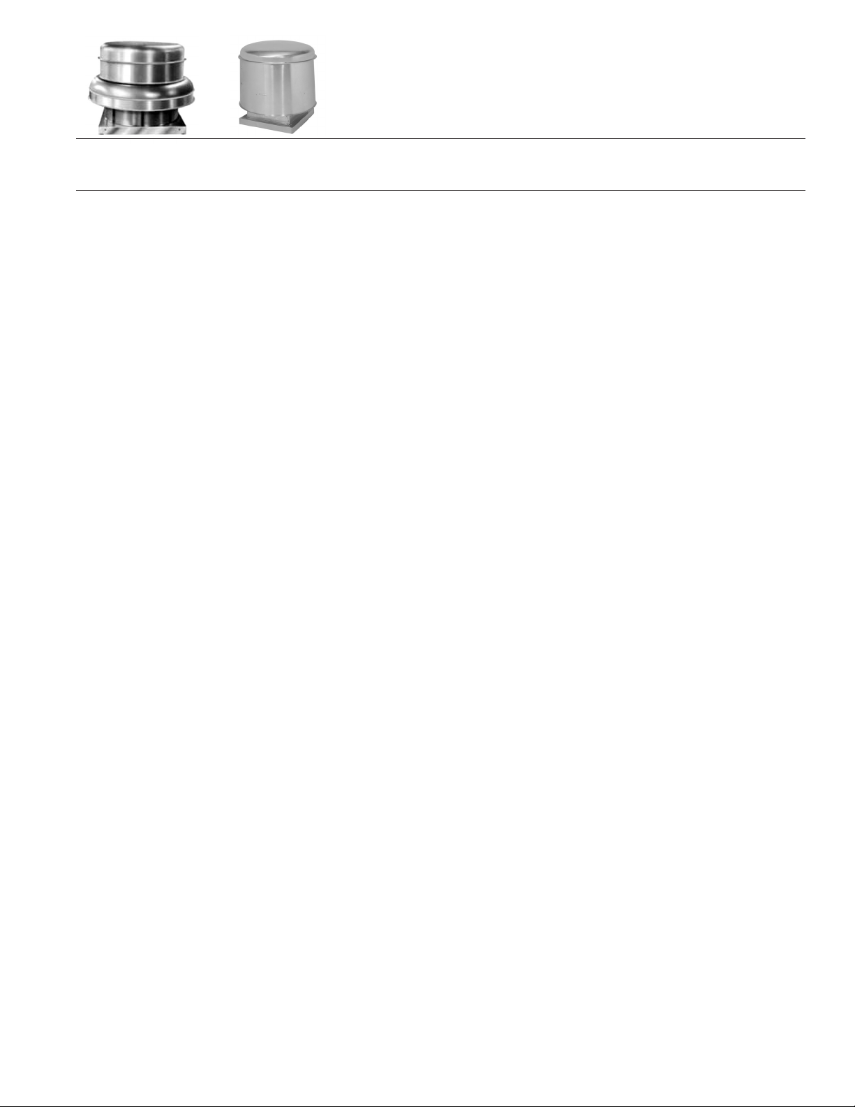
INSTALLATION & MAINTENANCE INSTRUCTIONS
Models PV (including PVH hurricane option) and USPV
For the PV Model with hurricane construction that complies
with Florida Building Code including High Velocity Hurricane
Zones (HVHZ) see the ADDITIONAL INSTALLATION AND
MAINTENANCE INSTRUCTIONS on page 4.
RECEIVING AND INSPECTION
Immediately upon receipt of a shipment, carefully inspect for
damage and shortage. Turn the impeller by hand to see that it
turns freely and does not bind. If any damage and/or shortage
is detected or suspected, the carrier must be asked to
conduct an inspection. The consignee’s representative should
not accept a shipment without a notation on the delivery
receipt indicating items not delivered or the apparent extent of
damage.
When a shipment is opened and damage is found which was
not evident externally (concealed damage), it is mandatory
that the consignee request an immediate inspection by the
carrier. Report any damage to the carrier within 15 days.
Failure to report damage within the above time limit will result
in rejection of a claim.
HANDLING
When handling fans and their accessories, always use
equipment and methods that will not cause damage. Fans
should be lifted using slings and padding or spreaders to
avoid damage.
CAUTION! Always make sure that all lifting and handling
equipment and techniques conform to current safety
standards.
Avoid lifting fans in a way that will bend or distort fan parts.
Never pass slings or timbers through the fan orifice.
CAUTION! Do not lift by the fan hood. Fans with special
coatings or paints must be protected in handling to prevent
damage.
STORAGE
Fans are protected against damage during shipment. If they
cannot be installed and put into operation immediately upon
receipt certain precautions are necessary to prevent
deterioration during storage. Responsibility for integrity of
fans and accessories during storage must be assumed by the
user. The manufacturer will not be responsible for damage
during storage. These suggestions are provided solely as a
convenience to the user, who shall make his own decision as
to whether to use any or all of them.
INDOOR: The ideal storage environment for fans and
accessories is indoors, above grade, in a low humidity
atmosphere which is sealed to prevent the entry of blowing
dust, rain, or snow. Temperatures should be evenly
maintained between 70°F and 105°F (wide temperature
swings may cause condensation and "sweating" of metal
parts). Windows should be covered to prevent temperature
variations caused by sunlight. Provide thermometers and
humidity indicators at several points and maintain the
atmosphere at 40% relative humidity, or lower.
It may be necessary to use trays of renewable desiccant or
portable dehumidifier to remove moisture from the air in the
storage enclosure.
Thermostatically controlled portable heaters (vented to
outdoors) may be required to maintain even temperatures
inside the enclosure.
CAUTION! Provide fire extinguishers, or fire alarms, or
emergency response communication to protect building and
equipment against fire damage. Be sure that building and
storage practices meet all local, state and federal fire and
safety codes.
The following fans or accessories must be stored indoors, in a
clean dry atmosphere:
a. Propeller wall fans not in wall housings.
b. Any fan protected by a cardboard carton.
c. Motors dismounted from fans.
d. Spare wheels or propellers.
e. Belts, sheaves, bushings and other parts when not
mounted on fan.
f. Boxes, bags or cartons of hardware.
g. Curbs
h. Dampers
Remove any accumulations of dirt, water, ice or snow and
wipe dry before moving to indoor storage. Allow cold parts to
reach room temperature to avoid “sweating” of metal parts.
Open boxes or cartons. Remove any accumulated moisture;
if necessary use portable electric heaters to dry parts and
packages. Leave coverings loose to permit air circulation and
to permit periodic inspection.
Rotate wheels or propellers by hand to distribute bearing
grease over the entire bearing surfaces.
Store at least 3 ½” off the floor on wooden blocks covered
with moisture proof paper or polyethylene sheathing. Provide
aisles between parts and along all walls, to permit air
circulation and space for inspection.
OUTDOOR: Fans designed for outdoor use may be stored
outdoors, if absolutely necessary. The storage area should
be reasonably level and drained or ditched to prevent
accumulation of water. Fencing and lighting for security are
desirable. Roads or aisles for portable cranes and hauling
equipment are needed. Consider the use of drift fencing to
minimize accumulation of blowing snow or dirt.
The following fans may be stored outdoors, if dry indoor
storage space is not available:
a. Fans intended for outdoor use that are crated in wood.
b. Wall fans installed in wall housings.
All fans must be supported on wooden blocks or timbers
above water or normal snow levels. Provide enough blocking
to prevent settling into soft ground. Fans should be set in
place using the directional arrow markings on the crate as a
guide.
Locate pieces far enough apart to permit air circulation,
sunlight, and space for periodic inspection. Place all parts on
their supports so that rain water will run off, or to minimize
water accumulation. Do not cover parts with plastic film or
tarps-these cause condensation of moisture from the air
passing through heating and cooling cycles.
Fan wheels and propellers should be blocked to prevent
spinning caused by strong winds.
INSPECTION AND MAINTENANCE
DURING STORAGE
Inspect fans and accessories at least once per month, while in
storage. Log results of inspection and maintenance per
formed. A typical log entry should include the following:
a. Date
b. Inspector’s Name
c. Name of Fan
-
Page 2

d. Location
e. Condition of Paint or Coating
f. Is moisture present?
g. Is dirt accumulated?
h. Corrective steps taken?
If moisture or dirt accumulations are found on parts, the
source should be located and eliminated. Fans should be
rotated at each inspection by hand ten to fifteen revolutions to
redistribute the motor and bearing lubricant.
If paint deterioration begins, consideration should be given to
touch-up or repainting. Fans with special coatings may
require special techniques for touch-up or repair.
Machined parts coated with rust preventive should be
restored to good condition promptly if signs of rust occur. The
most critical items are pulleys, shafts and bearing locking
collars. At the first sign of rusting on any of the above parts,
remove the original rust preventive coating with petroleum
solvent and clean lint-free cloths. Polish any remaining rust
from surfaces with crocus cloth or fine emery paper and oil.
Do not destroy the continuity of the surfaces. Wipe clean
with lint-free cloths and recoat surfaces evenly and thoroughly
with Tectly 506 (Ashland Oil Company) or equal. For hard to
reach internal surfaces or for occasional use, consider using
Tectly 511M Rust Preventive or WD40 or equal.
REMOVING FROM STORAGE
As fans are removed from storage to be installed in their final
location, they should be protected and maintained in similar
fashion, until the fan equipment goes into operation.
INSTALLATION
For the PV Model with hurricane construction that complies
with Florida Building Code including High Velocity Hurricane
Zones (HVHZ) see the ADDITIONAL INSTALLATION AND
MAINTENANCE INSTRUCTIONS on page 4.
1.
CAUTION! This unit has rotating parts and safety
precautions should be exercised during installation,
operation and maintenance.
2.
WARNING! Do not use in hazardous environments
where fan’s electrical system could provide ignition to
combustible or flammable materials, unless unit is
specifically built for hazardous environments.
3.
WARNING! If gases, other than clean air, are to be
exhausted using the fan, then the user bears the
responsibility of determining that the fan is appropriate
and safe for the application.
4. If the fan manufacturers prefab curb is used, a flange is
provided for mounting the damper. Damper should be
installed before setting exhauster.
5. If damper box is being used, assemble box and mount in
curb before setting exhauster. Damper may be installed
at this time if desired. Damper should be fastened to the
bottom of the damper box, curb flanges or nailing strips
in curb.
6. Remove motor compartment cover and mount motor
onto drive base. (Larger motors are shipped not
mounted because of the possibility of shipping damage.)
Refer to Figure 3 for sizes 75-240 and Figure 2 for
Hurricane model). The motor is mounted directly to the
slots on the drive base using the four motor mount bolts
with their nuts. For sizes 75-135, motors with 1
(38mm) shaft length use upper set of slots on the drive
base. For motors with shaft longer than 1
lower set of slots on the drive base. Belt tensioning is
1
" (38mm) use
2
1
brought about by sliding the motor away from the fan
pulley and then tightening the motor mount bolts and
nuts.
Belt should depress its width when pressed firmly inward
at midway point between the pulleys. Connect the wiring
and conduit, if used, from the disconnect switch to the
motor.
For fan sizes 260 through 300, refer to Figure 4, for size
365 refer to Figure 5 and for size 425 through 543 refer
to Figure 6. Motor adjustment rails are provided. Most
motors for these sizes are shipped separately. The motor
is to be bolted to the motor adjustment rails using the
motor mount bolts, nuts and washers. Install belt(s) and
check for tension. Belt tensioning is accomplished by
loosening the motor adjustment rail bolts and nuts, and
also the belt jack locknut. The two (2) belt jack bolts are
then turned clockwise to tighten the belt. After proper belt
tension is reached, the motor adjustment rail bolts and
nuts and belt jack locknuts must be tightened. The proper
belt tension is described above. The electrical wiring
connections can now be made and the flexible steel
conduit (where used) may be connected to the motor.
7. Turn impeller by hand to make sure it rotates freely. If
impeller hits orifice, adjust as follows:
For fans with duplex split pillow block bearings,
3-dimensional adjustment is provided. Horizontal
movement for adjustment is allowed by four (4) bolts in
the separator pan. Loosen the four nuts in the outer
edge (one in each quadrant) of the separator pan for
adjustment in all horizontal positions, re-tighten the four
nuts. Vertical movement for adjustment is allowed by two
(2) slots in the motor base bearing housing at the top and
bottom. The set screws can be loosened and the shaft
can be raised or lowered. Then the set screws must be
re-tightened following the set screw tightening procedure
in Table 1.
Fans with unitary pillow block bearings have the same
adjustment capability and is accomplished in the same
manner as described above with one exception. The
vertical adjustment is carried out by loosening the
bearing set screws and carefully sliding the fan shaft to a
new location. Tighten all bearing set screws (see Table 1
for torque recommendations) into the fan shaft when
complete.
WARNING! Do not damage the orifice when adjusting
the wheel.
8.
CAUTION! Guards must be installed when fan is within
reach of personnel or within eight (8) feet (2.5m) of
working level or when deemed advisable for safety.
9.
CAUTION! Before proceeding, make sure electrical
service to fan is locked in “OFF” position.
10. All wiring should be in accordance with local ordinances
and the National Electric Code.
11.
WARNING! Check voltage at the fan to see if it
corresponds with the motor nameplate. High or low
voltage can seriously damage the motor. Extra care
should be taken when wiring two speed motors since
improper connections will damage motor and void motor
warranty. Leave enough slack in wiring to allow for motor
movement when adjusting belt tension.
12. Apply power momentarily and compare the rotation of the
impeller with the directional arrow on fan. Wheel rotation
is clockwise as viewed from drive side. WARNING!
Operation in the wrong direction will deliver air but will
"
2
overload the motor to the extent of blowing fuses, and
seriously damaging the motor. In the case of three phase
motors, the direction can be changed by interchanging
any two of the three motor leads. In the case of single
phase motors, the reversing instructions will appear on
the wiring diagram in the motor wiring compartment.
13. Using a minimum of eight (8) lag bolts - two (2) on each
side near corners, securely fasten fan to curb. Fasten
all bolts securely. The fan should rest on the curb as
level as possible.
Page 2
Page 3
MAINTENANCE
For the PV Model with hurricane construction that complies
with Florida Building Code including High Velocity Hurricane
Zones (HVHZ) see the ADDITIONAL INSTALLATION AND
MAINTENANCE INSTRUCTIONS on page 4.
1. Under normal usage, no spare parts are recommended
for one year of operation. Recommended spare parts are
shown on pages 5 through 9.
CAUTION! Before proceeding, make sure electrical
service to fan is locked in “OFF” position.
WINDMILLING: Even when the power supply is locked
out, fans may cause injury or damage if the impeller is
subject to “windmilling” which is the turning of the
impeller and drive components due to a draft in the
system. To guard against this hazard, the impeller
should be secured to physically restrict rotational
movement.
2. Impeller shaft bearings on units with duplex split pillow
block housing are permanently lubricated and do not
require relubrication. Units with unitary pillow block
bearing have grease fittings and, under normal operation
will need no relubrication for 3 to 5 years. If relubrication
is required, use a grease conforming to NLGI No. 2.
CAUTION! Lubricating bearings with a high pressure gun
can blow bearing seals and overfill the bearing with
grease. This condition can result in excessive churning
and overheating. For normal operating conditions it is a
standard practice to fill only 30% of the bearing void with
grease. Do not over lubricate.
3. Motor bearings are prelubricated. Consult information
printed on motor for lubrication instructions.
4. Check belt tension after first 48 hours of operation and
thereafter annually. Belt should depress its width when
pressed firmly inward at midway point between the
pulleys. Too much tension will damage bearings. Belt
should be tight enough to prevent slippage. When
replacing worn belt, replace motor pulley if “shoulder” is
worn in groove.
WARNING! Do not replace the motor pulley with a larger
diameter pulley. Do not replace the fan pulley with one
smaller in diameter. The pulley ratios are set so that the
motor will not be overloaded. Do not operate at speeds
higher than that cataloged for this equipment.
5. If impeller shaft bearings need replacement, replace with
bearings comparable to the original equipment. If duplex
split pillow block bearings are used, install new bearings
into neoprene rings, check correct position of impeller
with orifice, position bearings in die-formed recess and
tighten set screws. (Minimum/maximum torque settings
shown in Table 1.) Replace die-formed bearing cap and
tighten four bolts.
NOTE: If locking collar type bearing is used, collar must
first be positioned against inner race on the bearing
nearest the impeller and turned in the direction of
impeller rotation with drift pin and hammer until it locks.
Locking collars must be on the inboard (facing) sides of
the bearings. Secure the bearing to the shaft with torque
set screw. Lock and secure the other bearing to the shaft
in the same manner.
NOTE: If pillow block type bearings are used, slide bear
ings onto shaft to desired location and bolt bearing block
securely to support base. Slide shaft back and forth in
secured bearing (do not drive with hammer) and rotate to
make certain it turns freely. Check correct position of im
peller with inlet orifice. Then secure bearings to shaft by
tightening set screws.
SET SCREW TIGHTENING SCHEDULE
1. Before initial operation of the fan, tighten set screws
according to the procedure outlined below.
2. After 500 operating hours or three months, whichever
comes first, tighten set screws to the full recommended
torque.
3. At least once a year, tighten set screws to the full
recommended torque.
PROCEDURE FOR TIGHTENING SET SCREWS IN
BEARINGS AND HUBS
One Set Screw Application
Using a torque wrench, tighten the set screw to the torque
recommended in Table 1.
Two Set Screw Application
1. Using a torque wrench, tighten one set screw to half of
the torque recommended in Table 1.
2. Tighten the second set screw to the full recommended
torque.
3. Tighten the first set screw to the full recommended
torque.
Table 1. Recommended Tightening Torque
for Set Screws
Set Screw Diameter Torque (in-lbs)
#10 35
1/4 80
5/16 126
3/8 240
7/16 384
1/2 744
9/16 1080
5/8 1500
3/4 2580
7/8 3600
1 5400
VARIABLE FREQUENCY
DRIVES AND MOTORS
There are occasions when a Variable Frequency Drive (VFD)
will cause poor motor performance and possible damage. To
avoid these problems, the Company recommends the
following:
1. Select compatible motor and VFD inverter; if possible,
the motor and the inverter should be from the same
manufacturer or at least the inverter selected should be
recommended by the motor manufacturer.
2. A motor shaft grounding system should be used to
-
prevent motor bearing damage from eddy currents.
NOTE: The Company will not honor motor warranty
claims if the customer fails to follow these recommenda
-
tions.
-
Page 3
Page 4

ADDITIONAL INSTALLATION AND MAINTENANCE INSTRUCTIONS
for the PV Model with hurricane construction that complies with Florida Building Code
including High Velocity Hurricane Zones (HVHZ)
This product has been issued by Miami-Dade County, Florida
an NOA No. 12-0706.08 with expiration date of May 5, 2016.
The full document can be found on Miami-Dade County,
Florida website www.miamidade.gov/building.
marked on its label by a statement “Miami-Dade County
Product Control Approved”.
This product shall be available for inspection at the job site at
the request of the Building Official.
This product may be installed on a wooden, metal or concrete
deck following the requirements shown in Figure 1. The
matching curb of Model CH for this particular use must be
used.
This product is
It is the installers responsibility to follow the installation
instructions including a check that all fasteners in the
outer shell of the product have been checked and
tightened.
If the fan has to be replaced, the curb for attachment of
the fan to the deck must also be replaced. The matching
curb of Model CH for this particular use must be used.
NOTE: Hurricane curbs have a tighter fit than standard
curbs.
Note: Curb mounting hardware provided by others.
Figure 1 - Installation of the product complying with Florida Building Code including High Velocity Hurricane
Zones (HVHZ) on a wooden, metal or concrete deck
Page 4
Page 5

Model with Hurricane Construction PV Sizes 75 through 240
Figure 2
PARTS LIST LEGEND
No. Description Qty No. Description Qty
0 Bag of Hardware (not shown) 1 12 Wheel* 1
1 Hood Top 1 13 Curb Cap 1
2 Hood Fastener ** 14 Separator Pan 1
3 Windband 1 15 Windband Bracket 2
4 Windband Reinforcement 1 16 Bearing Cap 1
5 Drive Belt* ** 17 Fan Sheave* 1
6 Motor Base 1 99 Shaft and Bearing Assembly 1
7 Motor Sheave* 1
8 Motor* 1
9 Disconnect Device 1
10 Conduit 1
11 Bird Screen **
* Recommended Spare Parts
**Quantities may vary depending on model size - please consult the factory
Page 5
Page 6

EXPLODED VIEW OF SIZES 75 THROUGH 240
Figure 3
PARTS LIST LEGEND
No. Description Qty No. Description Qty
0 Bag of Hardware (not shown) 1 12 Curb Base and Orifice 1
1 Hood Top 1 13 Wheel* 1
2 Hood Fastener ** 14 Pan Separator 1
3 Windband 1 15 Bearing Cap 1
4 Motor Base 1 16 Fan Sheave* 1
5 Drive Belt* ** 99 Shaft and Bearing Assembly 1
6 Motor Sheave* 1
7 Motor* 1
8 Windband Bracket 2
9 Disconnect Device 1
10 Bird Screen 2
11 Conduit 1
* Recommended Spare Parts
**Quantities may vary depending on model size - please consult the factory
Page 6
Page 7

EXPLODED VIEW OF SIZES 260 THROUGH 300
Figure 4
PARTS LIST LEGEND
No. Description Qty No. Description Qty
0 Bag of Hardware (not shown) 1 12 Curb Base and Orifice 1
1 Hood Top 1 13 Lower Hood Supports 8
2 Hood Top Side 1 14 Conduit 1
3 Motor Support Strut 2 15 Disconnect Device 1
4 Bearing Support Strut 1 16 Hood Support Bracket 8
5 HZ Support Strut 1 17 Motor Rails 1
6 Drive Belt* ** 18 Motor* 1
7 Motor Base 1 19 Motor Sheave* 1
8 Lower Hood Upper Part 1 20 Bearing Cap 2
9 Lower Hood Lower Part 1 21 Fan Sheave* 1
10 Wheel* 1 99 Shaft and Bearing Assembly 1
11 Bird Screen 2
* Recommended Spare Parts
**Quantities may vary depending on model size - please consult the factory
Page 7
Page 8

EXPLODED VIEW OF SIZE 365
Figure 5
PARTS LIST LEGEND
No. Description Qty No. Description Qty
0 Bag of Hardware (not shown) 1 12 Curb Base and Orifice 1
1 Hood Top 1 13 Lower Hood Supports 8
2 Hood Top Side 1 14 Conduit 1
3 Motor Support Strut 2 15 Disconnect Device 1
4 Bearing Support Strut 1 16 Hood Support Bracket 8
5 HZ Support Strut 1 17 Motor Rail 1
6 Drive Belt* ** 18 Motor* 1
7 Motor Base 1 19 Motor Sheave* 1
8 Bearing Cap 2 20 Fan Sheave* 1
9 Lower Hood Assembly 1 99 Shaft and Bearing Assembly 1
10 Wheel* 1
11 Bird Screen 2
* Recommended Spare Parts
**Quantities may vary depending on model size - please consult the factory
Page 8
Page 9

EXPLODED VIEW OF SIZES 425 THROUGH 543
Figure 6
PARTS LIST LEGEND
No. Description Qty No. Description Qty
0 Bag of Hardware (not shown) 1 12 Curb Base and Orifice 1
1 Hood Top Assembly 1 13 Lower Hood Supports 8
2 Drive Belt* ** 14 Conduit 1
3 Motor Support Strut 2 15 Disconnect Device 1
4 Bearing Support Strut 1 16 Hood Support Bracket 8
5 HZ Support Strut 1 17 Motor Rail 1
6 Fan Sheave* 1 18 Motor* 1
7 Motor Base 1 19 Motor Sheave* 1
8 Bearing Cap 2 99 Shaft and Bearing Assembly 1
9 Lower Hood Assembly 1
10 Wheel* 1
11 Bird Screen 3
* Recommended Spare Parts
**Quantities may vary depending on model size - please consult the factory
Page 9
Page 10

TERMS AND CONDITIONS OF SALE
ACCEPTANCE All orders and sales are subject to
written approval and acceptance by an executive offi
cer of Acme Engineering & Manufacturing Corporation
at Muskogee, Oklahoma, (the "Company") and are not
binding on the Company until so approved.
DELIVERY All shipping and delivery dates are esti
mated only. No delays in delivery will subject the
Company to any costs, damages or fees for late deliv
ery. Delivery of the products herein specified shall be
made F.O.B. point of shipment, unless otherwise
stated. The Company shall not be liable for delay due
to causes beyond its reasonable control, such as Acts
of God, acts of the purchaser, acts of civil or military
authorities, priorities, fires, strikes, floods, epidemics,
war, riots, delays in transportation, car shortages, and
inability, due to reasons beyond its reasonable control,
to obtain necessary labor, material, or manufacturing
facilities. In the event of such a delay, the date of deliv
ery shall be extended for a period equal to the time lost
by reason of the delay.
TERMS OF PAYMENT If, in the judgment of the Com
pany, the financial condition of the purchaser at any
time does not justify continuation of manufacture or
shipment on the terms of payment specified, the Com
pany may require full or partial payment in advance.
Pro rata payments shall become due as shipments are
made. Each shipment or delivery shall constitute a
separate sale, and the default of any shipment or deliv
ery shall constitute a separate sale, and the default of
any shipment or delivery shall not vitiate the contract
as to other shipments or deliveries.
SALES AND SIMILAR TAXES The Company’s prices
do not include sales, use, excise, or similar taxes.
Consequently, in addition to the price specified herein,
the amount of any present or future sales, use, excise,
or other similar tax applicable to the sale of the product
herein shall be paid by the Purchaser, or in lieu thereof
WARNING Acme products are designed and manufactured to provide reliable performance but they are not guaranteed to be 100% free of defects. Even reliable products will
experience occasional failures and this possibility should be recognized by the Purchaser and all End Users. If these products are used in a life support ventilation system
where failure could result in loss or injury, the Purchaser and all End Users should provide adequate back-up ventilation, supplementary natural ventilation or failure alarm sys
tem, or acknowledge willingness to accept the risk of such loss or injury.
WARNING DO NOT use in HAZARDOUS ENVIRONMENTS where fan’s electrical system could provide ignition to combustible or flammable materials unless unit is specifi
cally built for hazardous environments. Comply with all local and national safety codes including the National Electrical Code (NEC) and National Fire Protection Act (NFPA).
CAUTION Guards must be installed when fan is within reach of personnel or within eight (8) feet (2.5 m) of working level or when deemed advisable for safety.
DISCLAIMER The Company has made a diligent effort to illustrate and describe the products accurately in all Company literature; however such illustrations and descriptions
are for the sole purpose of identification and do not express or imply any warranty.
the Purchaser shall provide the Company with a tax
-
exemption certificate acceptable to the taxing authori
ties.
CANCELLATION Any contract resulting from the Pur
chaser’s order may be canceled by the Purchaser only
-
by negotiations and upon payments of reasonable can
cellation charges which will take into account expenses
-
already incurred and commitments made by the Com
pany.
DESIGN CHANGES The Company reserves the right
to make changes in design, improvements and addi
tions in and to its products any time without imposing
any liability or obligations to itself to apply or install the
same in any product manufactured by it.
TITLE The title and right of possession of the products
sold herein shall remain with the Company and such
products shall remain personal property until all
payments herein (including deferred payments whether
evidenced by notes or otherwise) shall have been
made in full in cash and the Purchaser agrees to do all
acts necessary to perfect and maintain such right and
title in the Company.
PRICE ADJUSTMENTS Prices are subject to change
upon notice by the Company. Prices on existing or
ders are subject to surcharges in the event of cost in
creases of metals and transportation. All complete
component accessory material manufactured by others
and furnished with the Company’s products such as
motors, drives, vibration equipment, controls or other
completely assembled component structures, are sub
ject to adjustment to the price at time of shipment re
gardless of the date of original order entry.
SAFETY ACCESSORIES The Company manufactures
products designed to serve multiple applications and
offers a wide range of safety equipment, including
guards and other devices, as may be required to meet
customer specifications. Without exception, the Com
pany recommends that all orders include applicable
safety devices. Products ordered without applicable
safety devices is clearly the responsibility of the Pur
chaser. Further, the Purchaser warrants that it has de
termined and acquired any and all safety devices re
quired for products sold by the Company. Weather
covers and guards for motor and V-belt drives, cou
plings, shafts and bearings, along with inlet and outlet
screens, are optional accessories noted in the price
list.
GOVERNING LAW The rights, obligations and reme
dies of Purchaser and the Company, the interpretation
of these terms and conditions and the sale of products
by the Company shall be governed by Oklahoma law,
without regard to any principles of conflict of laws.
ARBITRATION Any dispute arising under or in con
nection with these terms and conditions or the sale of
products shall be settled by binding arbitration admin
istered by the American Arbitration Association under
its Commercial Arbitration Rules, and judgment on the
award rendered by the arbitrator may be entered in
any court having jurisdiction thereof. The dispute shall
-
be resolved by one neutral arbitrator who shall have no
-
affiliation with either Purchaser or the Company and
shall be selected by the American Arbitration Associa
tion office in Dallas, Texas. The arbitration proceed
ings shall be held in Muskogee, Oklahoma.
APPLICABLE DOCUMENTS The agreement be
tween the Company and the Purchaser relating to the
products includes these terms and conditions of sale,
any applicable installation and maintenance instruc
tions provided by the Company and any terms appear
ing on the Company’s quotation, sales order acknowl
edgment and invoice.
LIMITED WARRANTY
WARRANTY AND DISCLAIMER: the Company ex-
tends this limited warranty to the original purchaser
and warrants that products supplied by the Company,
shall be free from original defects in workmanship and
materials for two years from date of shipment (except
for the warranty periods noted for products listed be
low), provided same have been properly handled,
stored, installed, serviced, maintained and operated.
This warranty shall not apply to products which have
been altered or repaired without the Company’s ex
press authorization, or altered or repaired in any way
so as, in the Company’s judgment, to affect its perfor
mance or reliability, nor which have been improperly
installed or subjected to misuse, negligence, or acci
dent, or incorrectly used in combination with other sub
stances. The Purchaser assumes all risks and liability
for results of use of all products.
Evaporative cooling pads are warranted to be free of
defects in materials and workmanship for a period of
two years from date of shipment provided same have
been properly handled, stored, installed, serviced,
maintained and operated; and further, not subjected to
excessive heat, corrosive agents or chemicals, or me
chanical abuse that may cause tearing, crushing or un
due deterioration, nor used on a system or in a manner
other than that for which it was designed as explained
in the product literature.
The following products are warranted to be free of de
fects in materials and workmanship for the periods
shown from date of shipment: Acme’s exclusive du
plex split pillow block bearings and shaft five years,
belts one year, Polyethylene tubing 90 days, AIR40
Heater warranty one year, AIR40 Emitter warranty
three years and DDP fan lifetime warranty on its pro
peller, cone, and housing.
LIMITATION OF REMEDY AND DAMAGES: All
claims under this warranty must be made in writing and
delivered to P. O. Box 978, Muskogee, Oklahoma,
74402, within 15 days after discovery of the defect and
prior to the expiration of two years from the date of
shipment by the Company of the product claimed de
fective, and Purchaser shall be barred from any
ACME ENGINEERING AND
MANUFACTURING CORPORATION
P.O. Box 978
Muskogee, Oklahoma 74402
Telephone 918/682-7791
Fax 918/682-0134
www.acmefan.com
Member Air Movement and Control Association International, Inc. July 2013 613097
remedy if Purchaser fails to make such claim within
such period.
Within 30 days after receipt of a timely claim, the Company shall have the option either to inspect the product
while in Purchaser's possession or to request Pur
chaser to return the product to the Company at Pur
chaser's expense for inspection by the Company. The
Company shall replace, or at its option repair, free of
charge, any product it determines to be defective, and
it shall ship the repaired or replacement product to
Purchaser F.O.B. point of shipment; provided, how
ever, if circumstances are such as in the Company’s
judgment to prohibit repair or replacement to remedy
the warranted defects, the Purchaser's sole and exclu
sive remedy shall be a refund to the Purchaser of any
part of the invoice price, paid to the Company, for the
defective product or part.
The Company is not responsible for the cost of re
moval of the defective product or part, damages due to
removal, or any expenses incurred in shipping the
product or part to or from the Company’s plant, or the
installation of the repaired or replaced product or part.
-
The warranties set forth above do not apply to any
components, accessories, parts or attachments manu
factured by other manufacturers; such being subject to
the manufacturer’s warranty, if any. To the extent not
prohibited by the manufacturer’s warranty, the Com
pany shall pass through to Purchaser such manufac
turer’s warranty.
THE COMPANY’S WARRANTY IS IN LIEU OF ALL
OTHER WARRANTIES, EXPRESS OR IMPLIED,
ARISING BY LAW OR OTHERWISE, INCLUDING
WITHOUT LIMITATION THE IMPLIED WARRANTIES
OF MERCHANTABILITY AND FITNESS FOR A PAR
TICULAR PURPOSE, WHICH ARE HEREBY EX
PRESSLY DISCLAIMED AND WAIVED. THIS WAR
RANTY CONSTITUTES THE COMPANY’S SOLE
AND EXCLUSIVE WARRANTY FOR DEFECTIVE
GOODS AND PURCHASER’S SOLE AND EXCLU
SIVE REMEDY FOR DEFECTIVE PRODUCTS.
-
No employee, agent, dealer, or other person is
authorized to give any warranties on behalf of the
Company or to assume for the Company any
other liability in connection with any of its products
except in writing and signed by an officer of the
Company.
REPLACEMENT PARTS If replacement parts are
ordered, purchaser warrants that the original com
ponents in which these replacement parts will be
placed are in satisfactory working condition, and
when said replacement parts are installed, the resultant installation will operate in a safe manner, at
speeds and temperatures for which the original product was purchased.
-
TECHNICAL ADVICE AND RECOMMENDATIONS,
-
DISCLAIMER: Notwithstanding any past practice or
dealings or any custom of the trade, sales shall not in
clude the furnishing of technical advice or assistance
or system design. Any such assistance shall be at the
Company’s sole option and may be subject to addi
-
tional charge.
The Company assumes no obligation or liability on ac
-
count of any recommendations, opinions or advice as
to the choice, installation or use of products. Any such
recommendations, opinions or advice are given and
shall be accepted at Purchaser's and End User's risk
and shall not constitute any warranty or guarantee of
such products or their performance.
LIMITATION OF LIABILITY The cumulative liability of
the Company to the Purchaser and any other persons
for all claims in any way relating to or arising out of the
products, including, but not limited to, any cause of ac
tion sounding in contract, tort, or strict liability, shall not
exceed the total amount of the purchase price paid for
those products which are the subject of any such
claim. This limitation of liability is intended to apply
without regard to whether other provisions of this
agreement have been breached or have proven inef
fective even if the Company has been advised of the
possibility of such claims or demands. In no event
shall the Company be liable to the Purchaser or any
other person for any loss of profits or any incidental,
special, exemplary, or consequential damages for any
claims or demands brought by the Purchaser or such
other persons.
-
INDEMNITY The Company’s maximum liability to Pur
chaser and to any end user is as set forth above. The
Company makes no warranty to anyone for any prod
ucts not manufactured by the Company and shall have
no liability for any use or installation of any products
(whether manufactured by the Company or other man
ufacturers) not specifically authorized by this sale.
Purchaser acknowledges various warnings by the
Company regarding the products and its installation
and use. If the Company incurs any claims, lawsuits,
settlements, or expenses (including attorney fees) for
any loss, injury, death or property damage including,
but not limited to, claims arising out of the Purchaser’s
-
or any end user’s installation or use of the products,
the Purchaser shall indemnify and hold the Company
harmless.
-
-
-
-
-
-
-
-
-
-
-
-
-
-
-
-
-
-
-
-
-
-
-
-
 Loading...