

Page 1
Page 2
CONSTRUCTION FEATURES
Models FN and FQ direct drive propeller fans are offered for commercial and industrial applications having
low noise and high pressure requirements.
FQ FANS
These fans are designed to operate more quietly than
conventional propeller fans and are recommended for
ventilating applications desiring less fan noise. FQ fans are
available in 10 sizes, 9" through 36" with a maximum capacity
of 17,800 CFM.
Fan panels are constructed of steel and range from 18 to 16
gauge.
Aluminum blade thickness is from .050 to .125.
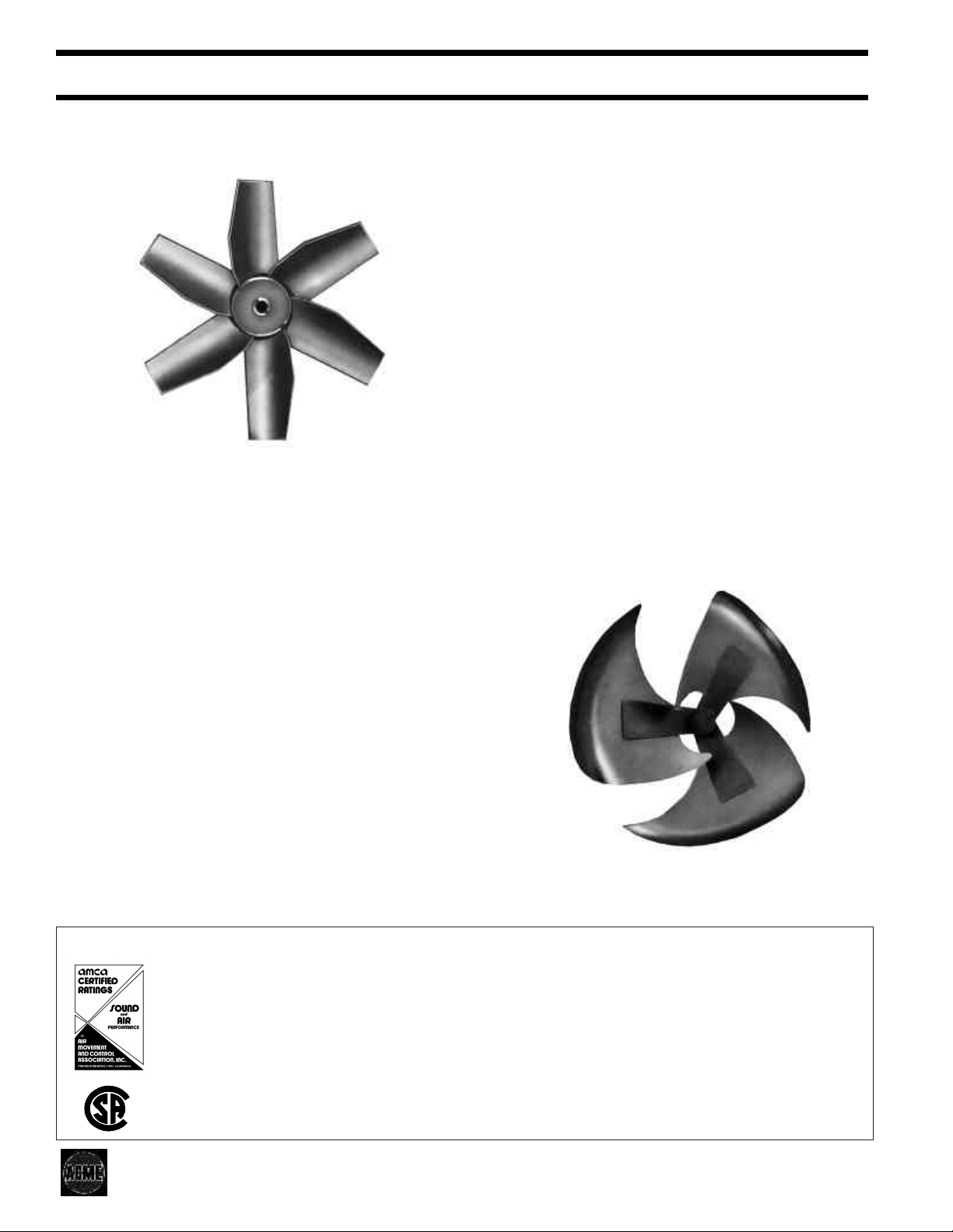
ADVANCED PROPELLER DESIGN
These propellers feature an advanced teardrop shape blade
designed for exceptionally low noise level performance.
Aluminum blades are fastened to a formed steel hub with
heavy duty oversize rivets. Propeller is precision balanced for
smooth operation.
FN FANS
FN fans are designed to operate up to 1" static pressure with
capacities to 22,400 CFM. Available in 9 sizes, 14" through
48”, these heavy duty fans are designed for industrial type
applications where extra strength and durability are desired.
Fan panels are constructed of steel and range from 18 to 14
gauge.
Aluminum blade thickness is from .080” to .125”.
The swept-back teardrop blade shape with its aerodynamic
leading edge propels the air through the streamlined orifice
with a minimum of air turbulence.
FQ not available with steel propeller.
HIGH PRESSURE PROPELLERS
For increased pressure requirements, FN propellers,
depending on size and horsepower, have four or six tapered
circular-arc airfoil blades. Standard construction is all welded
heavy duty aluminum that is precision balanced.
Non-overloading design prevents motor overload when
operated within cataloged static pressure ranges. Optional
steel prop is available for all FN fans, except size 48".
LICENSED RATINGS FOR SOUND AND AIR
Acme Engineering & Manufacturing Corp. certifies that the FQ and FN Propeller Fans shown herein are licensed to bear the
AMCA Seal. The ratings shown are based on tests and procedures performed in accordance with AMCA Publication 211 and
AMCA Publication 311 and comply with the requirements of the AMCA Certified Ratings Program.
The sound ratings shown are loudness values in fan sones at 5 feet in a hemispherical free field calculated per AMCA Standard
301. Values shown are for installation Type A: Free Inlet fan sone levels.
Most Acme FQ and FN fans are listed by the Canadian Standards Association Testing Laboratory as approved.
Page 2
Page 3
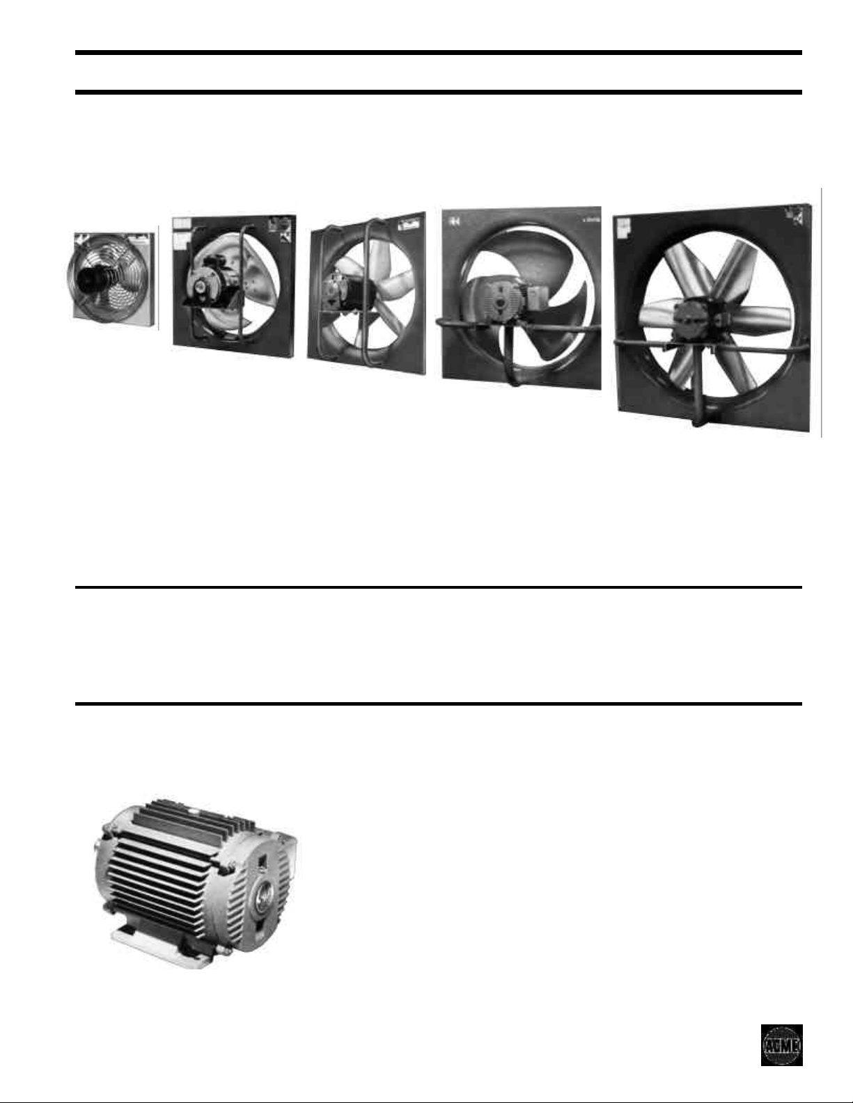
CONSTRUCTION FEATURES
FAN PANEL - Construction of heavy
gauge steel. Wide flange on all four
sides provides extra strength and rigidity
to reduce the possibility of vibration and
for a more secure installation. Standard
finish is acrylic epoxy.
FQ09 AND 10
FQ12 THRU 18
EXHAUST MODELS FQ09 and 10
utilize the rugged motor side wire guard
as the motor support means thereby
making this guard standard equipment.
Front (propeller side) guard is optional.
FQ09 and FQ10 are not available in
reverse flow (supply).
STREAMLINED ORIFICE - Die formed
for uniformity, the deep streamlined
orifice provides for high efficiency airflow
throughout the propeller.
FN14 THRU 18
FQ21 THRU 36
EXHAUST MODELS FQ12 to 36 have
the motor mounted on an all welded
steel plate and formed pipe frame
assembly for extra strength and rigidity.
Front and back guards are optional on
these sizes. FQ1210 and FQ129 are
not available in reverse flow (supply).
EASY TO INSTALL - Prepunched holes
in flange saves on installation time and
cost.
MOUNT IN ANY POSITION - All motors
are equipped with all-angle thrust ball
bearings.
FN21 THRU 48
EXHAUST MODELS FN14 to 48 have
the motor mounted on an all welded
steel plate and formed pipe frame
assembly for extra strength and rigidity.
Front and back guards are optional on
all sizes.
Supply fans are available in all models
except FQ09, 10, 1210 and 129. The
airflow capacity is the same as for
exhaust type fans as shown on page 4.
REVERSE FLOW (SUPPLY) FANS
Only circular basket type guards are
available with these fans.
When supply type fans are used with
motorized wall dampers, it is
recommended to use WAGC and
RESERVE MOTOR POWER - Fans are
designed with conservative motor
loadings and efficient motor cooling to
obtain longer motor life under
continuous duty operation.
All motors are totally enclosed type with
lubricated sealed ball bearings. All
single phase motors have automatic
resetting thermal overloads for low
voltage protection.
Models FQ09, 10, 1210 & 129 use two
speed tapped winding, single phase,
shaded pole type ball bearing motors
only.
WAGCH center pivot dampers. A
time delay is recommended in the fan
motor’s starter control circuit to
allow the damper to fully open before
the fan is activated.
All other models have split phase,
capacitor start, capacitor run, or
permanent split capacitor single phase
motors. Some are available in two
speed types.
Explosion resistant and three phase
single speed motors are also available
for some models. Consult your Acme
Representative for more details plus
availability of motors.
Single phase motors are resilient
mounted in circular neoprene vibration
isolators integral with the motor base.
Page 3
Page 4

PERFORMANCE DATA
FAN
MODEL
FQ098LO
FQ098HI
FQ108LO
FQ108HI
FQ1210LO
FQ1210HI
FQ129LO
FQ129HI
FQ12D4
FQ14C6
FQ14F4
FN14D4
FN14E4
FQ16C6
FQ16F4
FQ16H4
FN16F4
FQ18E6
FQ18G6
FQ18H4
FN18G4
FQ21G6
FQ21K4
FN21J4
FN21K4
FQ24F8
FQ24H6
FN24J6
FN24J4
FN24L4
FQ30H8
FQ30K8
FQ30M6
FN30L6
FN30M6
FQ36K8
FQ36L8
FN36K8
FN36L6
FN36M6
FN42K8
FN42L8
FN42M8
FN48K8
FN48L8
FN48M8
TIP
RPM
SPEED
Ft/Min
1500
3435
1650
3780
1500
3925
1650
4320
3030
980
3280
1060
4180
1350
4795
1550
5445
1760
1160
4150
1760
6295
1760
6450
1760
6450
1160
4800
1760
7280
7280
1760
1760 7370 1/3 17 3200 3030 2980 2740 2480 2170 1500 1350 .393 36
1160
5505
1160
5505
8350
1760
1760 8290 1/2 21 4170 4000 3960 3760 3520 3250 2950 2520 2040 .571 33
1160
6325
1760
9595
1760
9670
1760
9670
860
5430
1160
7325
1160
7280
1760
11050
11050
1760
860
6700
6700
860
9035
1160
1160
9110
1160
9110
860
8020
860
8020
8100
860
10930
1160
10930
1160
860
9456
860
9456
9456
860
860
10800
860
10800
10800
860
SONES
HP
1/28
1/28
1/28
1/2866
1/28
1/28
1/8
1/8
1/6
1/8
1/3
1/6
1/4
1/6
1/3
3/4
1/4
1/2
3/4
1/2
1 1/21324
1 1/23030
1/3
3/4
1 1/2
1 1/2
1 1/2
1 1/2
1 1/2
1
1
1
2
3/4
3
2
3
2
2
3
2
3
2
3
@
.100”SP
10
14141880
16
17
12
17
10145550
23
39
40
18
14
21
303112450
212214450
27
43
43
32
33
43
36
39
41
CFM vs. STATIC PRESSURE
.000” .100” .125” .250” .375” .500” .625” .750” .875” 1.000” Lbs.
8
455
355
500
620
685
870
4
940
4
1200
5
1380
6
1565
8
7141625
2460
2160
2180
8
2580
3710
3210
9
4030
4870
5250
6750
6330
8150
7140
8150
6420
9590
8860
11600
15100
16040
17800
13160
14280
17740
17560
19400
22320
17120
19340
22400
10970
14660
12100
15500
13800
17000
12650
13920
17360
16700
18600
21650
15900
18200
21600
385 b 70
410
530
505
600
580
565
645
685
750
1030
1075
1280
1475
1440
2380
1780
2050
2020
2490
3600
2960
3720
4720
5020
6570
6150
7930
5110
6820
7760
6220
9400
8310
1245
1450
1375
2350
1750
2020
1960
2460
3570
2890
3640
4670
4950
6530
6100
7880
4990
6750
7660
6190
9360
8150
10800
14570
12000
15420
13620
16800
12520
13820
17270
16340
18220
21450
15530
17930
21440
1035
1090
1295
2170 1940
1600
1430
1850
1640
1620
2150
2320
3240
3430
2500
2730
3300
4220
4450
4550
4080
6300
6050
5860
5600
7590
7250
4200
5660 4850
6260
6350
7080
5700
5950
8870
9110
6380
7330
9000
9950
13330
13980
11500
10900
14750
14000
12580
11570
15800
14700
10950
11800
12700
13300
16200
16780
14970
16980
19000 16250
20460
12400
13950
15060
16550
18940
20360
1300 965 760
1850
2770
3010
3960
5780 5490 5160 4700
5320
6880
5450
8590
12610 11900 11130
10300
13150
13300
9900
12050
15600
10640
13360
17170
3700
5020
6440
5170
8210
9580
12050
8500
11400
15000
9025
11630
15260
3350
4690
4290 3800
5840
4870
4530
7950
7600
8720 7750
6600
5250
10700
10000
14300
6000
7420
8240
9900
11285
13110
4180
7200
4000
4300
6840
10090
MAX
BHP
b120
.027
.034
.069
.105
.158
.100
.353
.208
.300
.148
.390
.685
.253
.470
.870
.610
1.5108391
1.089
1.7126882
.389
.882
.980
1.070
2.100
.830
1.370
3.060
1.96
3.03
1.640
2.420
1.66
2.26
3.14
1.80
2.26
3.45
1.71
2.19
3.01
FAN
SHIP WT.
15
15
17
17
27
27
27
27
29
32
35
32
35
37
40
40
40
48
48
93
93
121
85
99
132
168
174
175
213
197
203
199
204
244
212
222
230
223
233
241
DAMPER
MODEL
WAG
WAG
WAG
WAG
WAG
WAG
WAG
WAG
WAG
WAGH
WAG
WAG
WAG
WAG
WAGH
WAG
WAG
WAGH
WAGH
WAG
WAGH
WAGH
WAGH
WAGH
WAG
WAGH
WAGH
WAGH
WAGH
WAG
WAGH
WAGH
WAGH
WAGH
WAGH
WAGH
WAG
WAGH
WAGH
WAG
WAGH
WAGH
WAG
WAG
WAGH
Performance shown is for Installation Type A: Free Inlet, Free Outlet.
The sound ratings shown are loudness values in fan sones at 5 ft
(1.5m) in a hemispherical free field calculated per AMCA Standard
301. Values shown are for Installation Type A: Free Inlet fan sone
levels.
Performance ratings do not include the effects of appurtenances in
the airstream; FQ12 through FQ48. Performance ratings include the
effect of a back guard (motor side) on models FQ09 and FQ10.
Model numbers shown are for Exhaust Fans with standard direction
of airflow (motor on intake side of propeller). For Supply Fans with
direction of airflow reversed (motor on discharge side of propeller)
add letter “R” to the model number; example: FN-R14.
Reverse flow (supply) not available for models FQ09, 10, 1210, and
129.
The brake horsepower (BHP) capability of a fan motor is dependent on the
degree of cooling the motor receives from the moving airstream over the
motor. The motor loading beyond the motor nameplate rating on Acme
built fans does not overheat the motor and is within NEMA recommended
limits. It is therefore not detrimental to the motor and is economically
desirable.
See Page 7 for damper model numbers and sizes.
b Watts
Page 4
Page 5

DIMENSIONAL DATA
EXHAUST FANS
FAN
MODEL
FQ09 12.00
FQ10 14.00
FQ12 16.00
FQ14 18.00
FN14 18.00
FQ16 21.00
FN16 21.00
FQ18 23.00
FN18 23.00
FQ21 26.50
FN21 26.50
FQ24 30.00
FN24 30.00
FQ30 37.50
FN30 37.50
FQ36 45.00
FN36 45.00
FN42 60.00
FN48 64.00
A B Max. C D E* F
In. In. In. In. In. In. Ga. In.
5.75
7.00
13.25
15.00
13.67
15.50
14.76
19.00
13.82
17.50
17.71
20.00
17.78
26.25
20.13
24.75
21.38
18.62
21.00
1.50 1.50
3.00 1.50
4.00 1.50
4.50 1.50
3.75 1.50
5.00 1.50
4.00 1.50
5.50 1.50
4.50 1.50
6.00 1.75
5.00 1.75
6.50 1.75
6.00 1.75
7.50 1.75
8.00 1.75
8.00 1.75
9.00 1.75
6.37 3.06
7.50 3.06
8.00
10.00
10.00
10.00
10.00
8.00
8.00
9.00
9.00
10.00
10.00
8.00
8.00
10.00
10.00
12.00
12.00
15.00
16.00
Metal Gauges
Orifice Blades
2.00 18 .050
2.00 18 .050
3.00 18 .063
4.00 18 .080
4.00 18 .080
2.50 18 .080
2.50 18 .080
2.50 18 .080
2.50 18 .080
3.25 16 .080
3.25 16 .080
3.00 16 .080
3.00 16 .125
3.75 16 .125
3.75 16 .125
4.50 16 .125
4.50 16 .125
7.50 14 .125
8.00 14 .125
SUPPLY FANS
FAN
MODEL
FQ-R12 16.00 14.75 2.50 1.50
FQ-R14 18.00 16.75 3.25 1.50
FN-R14 18.00 13.50 1.50 1.50
FQ-R16 21.00 20.00 4.50 1.50
FN-R16 21.00 17.00 1.50 1.50
FQ-R18 23.00 21.75 4.00 1.50
FN-R18 23.00 19.00 1.50 1.50
FQ-R21 26.50 22.00 2.75 1.75
FN-R21 26.50 22.00 1.75 1.75
FQ-R24 30.00 21.00 1.50 1.75
FN-R24 30.00 25.00 1.75 1.75
FQ-R30 37.50 27.09 4.50 1.75
FN-R30 37.50 25.50 1.75 1.75
FQ-R36 45.00 25.25 5.00 1.75
FN-R36 45.00 30.00 1.75 1.75
FN-R42 60.00 30.50 2.00 3.06
FN-R48 64.00 32.25 2.50 3.06
A B Max. C D E* F
In. In. In. In. In. In. Ga. In.
10.00
10.00
10.00
8.00
8.00
9.00
9.00
10.00
10.00
8.00
8.00
10.00
10.00
12.00
12.00
15.00
16.00
*The number of holes varies depending on fan size.
FQ09 thru FN14 - 2 Holes, FQ16 thru FN21 - 3 Holes,
FQ24 thru FN48 - 4 Holes.
Typical drawings for dimensional purposes only, which are correct
within limits suitable for normal installation requirements and do not
necessarily show actual construction.
Metal Gauges
Orifice Blades
3.00 18 .063
4.00 18 .080
4.00 18 .080
2.50 18 .080
2.50 18 .080
2.50 18 .080
2.50 18 .080
3.25 16 .080
3.25 16 .080
3.00 16 .080
3.00 16 .125
3.75 16 .125
3.75 16 .125
4.50 16 .125
4.50 16 .125
7.50 14 .125
8.00 14 .125
Page 5
Page 6

SAFETY GUARDS
OPTIONAL ACCESSORIES
CIRCULAR TYPE
(SIZE 09 THRU 18)
Attractive circular type safety guards are
available for exhaust type fans through
size 18. They are constructed of heavy
gauge concentric wire rings welded to a
frame and finished with electroplated
zinc to produce attractive sturdy guards
that comply with OSHA standards.
The motor side circular guards for FQ09
and FQ10 are integral with the motor
mounting frame and are standard
equipment.
The circular type wire guards are
available for the motor and propeller
sides as optional equipment for exhaust
fan sizes 12 through 18.
COATINGS
Aluminum and galvanized components
remain unpainted as a standard finish,
but when required, are processed
through the finishing system to apply
decorative or special coatings. A high
turbulence oven is used to produce a
baked on finish for most special
coatings. Decorative coatings are not
baked on.
DECORATIVE COATINGS
Acme offers 16 popular colors for
decorative finishes utilizing an industrial
grade enamel applied to the exterior of
fan. Special colors are available upon
request. See your Acme Representative
for complete color selections.
SQUARE TYPE
(SIZE 21 THRU 48)
Extruded aluminum frame guards Model
BA for back (motor side) and Model FA
for front (propeller side) are available for
fan sizes 21 through 48. Constructed of
½” x 1” mesh heavy gauge welded
galvanized wire and are open on all
sides for maximum airflow. Guards are
shipped knocked down, easily
assembled with connecting clips which
bolt to fan frame and are easily removed
for servicing the fan.
The openings for these guards comply
with OSHA standards.
Optional guards are also available for
reverse flow (supply type) fans from
sizes 12 through 48.
SPECIAL COATINGS
Products receiving special coatings have
components painted before assembly.
Fasteners are not painted.
• ACRYLIC EPOXY
This product provides a more durable
surface.
• CARBOLINE SANITILE
(Eisenheiss)
This air dry synthetic polyester forms a
black coating that offers greater
resistance to most organic and inorganic
acids.
CAUTION! Guards must be installed
when a fan is within reach of personnel or
within seven (7) feet of working level or
when deemed advisable for safety.
• HERESITE (Air Dry)
A phenolic coating with greater
resistance to most organic and inorganic
acids.
• INSULMASTIC
A black asphalt based mastic that
provides some condensation control,
sound deadening and corrosion
resistance.
NOTE: For any coating selected the user
assumes the responsibility for the
corrosive agent, its concentration,
temperature, moisture content and the
ultimate effect on the coating and
equipment.
Page 6
Page 7

OPTIONAL ACCESSORIES
DAMPER (Model WAG or WAGC)
Constructed of rigid galvanized steel frame with double tie
rods on the blades. Blades are industrial grade aluminum
reinforced with steel rods. Nylon bearings are used to
resist corrosion and prevent damper sticking making for
quieter operation.
HEAVY DUTY DAMPER
(Model WAGH or WAGCH)
Heavy duty dampers are recommended when the air
velocity exceeds 1500 FPM and up to 2500 FPM. Heavy
duty dampers are similar in construction to standard duty
dampers except each blade has a formed reinforcement
member providing extra strength and rigidity.
CENTER PIVOT
DAMPER
(Model WAGC or
WAGCH)
When a supply type
fan is used, a
motorized center
pivot type damper,
model WAGC-MT or
WAGCH-MT should
be substituted for the
WAG or WAGH. For
2 HP units and
larger, it is
recommended that a
time delay switch be
utilized. For center
pivot damper add “C”
to damper model
number.
AUTOMATIC DAMPERS
Wt.
Lbs.
Damper
11 x 11 14 x 14
13 x 13 16 x 16
15 x 15 18 x 18
18 x 18 21 x 21
20 x 20 23 x 23
23 x 23 26 x 26
27 x 27 30 x 30
34 x 34 37 x 37
42 x 42 45 x 45
57 x 57 60 x 60
57 x 57 60 x 60
FAN
MODEL
FQ09
FQ10
FQ1210 - 12 WAG1616 9 WAGH1616 10
FN/FQ14
FN/FQ16
FN/FQ18
FN/FQ21
FN/FQ24 WAG3030 17 WAGH3030 19
FN/FQ30
FN/FQ36
FN42
FN48 WAG6060 54 WAGH6060 61
Models 1212 through 3737 are single panel; 4545 through 6060 are double panel.
Maximum velocity for WAG style is 1500 FPM. Maximum velocity for WAGH style is 2500 FPM.
Use WAGC-MT or WAGCH-MT for supply (reverse) installations.
Standard Duty Heavy Duty
Model
WAG1212 6 WAGH1212 7
WAG1414 8 WAGH1414 9
WAG1818 10 WAGH1818 11
WAG2121 11 WAGH2121 12
WAG2323 12 WAGH2323 13
WAG2626 14 WAGH2626 15
WAG3737 24 WAGH3737 26
WAG4545 30 WAGH4545 33
WAG6060 54 WAGH6060 61
Wt.
Lbs.
Model
Overall
Size
In. In.
9 x 9 12 x 12
Size
WARNING! Supply type fans utilizing a motorized wall damper should
have a time relay in the fan motor’s starter control circuit to allow the
damper to fully open before the fan is activated.
Automatic, Motorized or Manual Operated.
Automatic dampers open with the airflow of the fan and are spring
closed. Not available with supply (reverse) type fans.
Motorized dampers use a stall type motor and are spring closed.
For motorized damper add “MT” to damper model number.
Manual dampers open with a pull chain and are spring closed. For
manual damper add “ML” to damper model number.
WALL COLLAR (Model WC)
For sizes 09 through 21 exhaust or
supply type. Designed for damper
to be installed flush with wall
surface. Damper is optional.
Constructed of galvanized steel.
(Shipped Knocked Down)
WALL COLLAR
Dimensions
FAN MODEL
FQ09 WC9FQ 12.25 10.00 15.25 10.00 2.63 18
FQ10 WC10FQ 14.25 10.00 17.25 12.00 2.63 20
FQ12 WC12FQ
FN/FQ14 WC14FQ
FN/FQ16 WC16FQ
FN/FQ16 WC18FQ
FN/FQ21 WC21FQ 26.75 13.00 29.25 24.00 2.88 35
Wall Collar
Model
A B C D E Weight
In. In. In. In. In. Lbs.
16.25 12.00 19.25 14.00 2.63 22
18.25 12.00 21.25 16.00 2.63 25
21.25 12.00 24.25 19.00 2.63 27
23.25 13.00 26.25 21.00 2.63 31
SOLID STATE SPEED
CONTROLLER Solid
state controllers are
available for selected
fans equipped with 115
volt, 60 Hz single
phase shaded pole and
smaller size permanent
split capacitor motors.
They provide a variable
speed control with
fewer parts to wear out
and eliminate the need for 2-speed
motors. Easily installed in a standard
wall box, they require a simple 2-wire
connection, but are equipped with a
third wire that maintains a constant
voltage to the damper motor in the
event a motorized wall damper is used
with the fan. Contact your Acme
Representative for 50 Hz requirements.
Page 7
Page 8

CENTRIFUGAL
VENTILATION FANS
DUCT FANS
PROPELLER AND
INLINE CENTRIFUGAL
CEILING, INLINE AND
CABINET FANS
CENTRIFUGAL &
PROPELLER ROOF
EXHAUST FANS
CENTRIFUGAL &
PROPELLER ROOF
SUPPLY FANS
CENTRIFUGAL AIR
HANDLING FANS
CENTRIFUGAL AND
PROPELLER UPBLAST
ROOF EXHAUSTERS
CENTRIFUGAL AND
PROPELLER
WALL FANS
CENTRIFUGAL
INDUSTRIAL
PROCESS FANS
MAKE-UP AIR SYSTEMS
CENTRIFUGAL
HEAVY DUTY
INDUSTRIAL FANS
EXHAUST &
SUPPLY VENTS
LIMITED WARRANTY Acme Engineering
and Manufacturing Corporation warrants the
products manufactured by Acme to be free
from original defects in workmanship and ma
terial for two years subject to the terms and
conditions of its published limited warranty.
Warranties on purchased products are sub
ject to the vendor’s warranty. Refer to current
Form MS149 for complete limited warranty
terms and conditions.
WARNING Acme products are designed and
manufactured to provide reliable perfor
mance but they are not guaranteed to be
100% free of defects. Even reliable products
ACME ENGINEERING &
MANUFACTURING CORP.
P.O. Box 978, Muskogee, Oklahoma 74402
Telephone: 918-682-7791 Fax: 918-682-0134
www.acmefan.com e-mail: acmefan@acmefan.com
will experience occasional failures and this
possibility should be recognized by the User.
If these products are used in a life support
-
ventilation systemwhere failure could resultin
loss or injury, the User should provide ade
quate back-up ventilation, supplementary
-
natural ventilation or failure alarm system, or
acknowledge willingness to accept the risk of
such loss or injury.
WARNING DO NOT use in HAZARDOUS
ENVIRONMENTS where fan’s electrical sys
-
tem could provide ignition to combustible or
flammable materials unless unit is specifically
built for hazardous environments.
CAUTION Guards must be installed when fan
is within reach of personnel or within seven (7)
feet (2.134 m) of working level or when
deemed advisable for safety.
DISCLAIMER The Company has made a dili
gent effort to illustrate and describe the prod
ucts in this literature accurately; however, such
illustrations and descriptions are for the sole
purpose of identification, and do not express or
imply a warranty that the products are mer
chantable, or fit for a particular purpose, or that
the products will necessarily conform to the il
lustrations or descriptions or dimension.
Member Air Movement and Control Association
September 2001 Form C4Q
-
-
-
-
 Loading...