

Page 1

ACME ENGINEERING &
MANUFACTURING CORP.
P.O. Box 978
Muskogee, OK 74402
Telephone 918/682-7791
Fax 918/682-0134
INSTALLATION & MAINTENANCE INSTRUCTIONS
CENTRI MASTER®FORWARD CURVE BLOWER
MODELS FCE, FCD, FCF, FCA, FCH, FCJ
RECEIVING AND INSPECTION
Immediately upon receipt of a shipment, carefully inspect for
damage and shortage. Turn the impeller by hand to see that
it turns freely and does not bind. If any damage and/or
shortage is detected or suspected, the carrier must be asked
to conduct an inspection. The consignee’s representative
should not accept a shipment without a notation on the
delivery receipt indicating items not delivered or the apparent
extent of damage.
When a shipment is opened and damage is found which was
not evident externally (concealed damage), it is mandatory
that the consignee request an immediate inspection by the
carrier. Report any damage to the carrier within 15 days.
Failure to report damage within the above time limit will
result in rejection of a claim.
HANDLING
When handling fans and their accessories, always use
equipment and methods that will not cause damage. Fans
should be lifted using slings and padding or spreaders to
avoid damage.
CAUTION! Always make sure that all lifting and handling
equipment and techniques conform to current safety
standards.
Avoid lifting fans in a way that will bend or distort fan parts.
Never pass slings or timbers through the fan orifice.
CAUTION! Do not lift by the fan hood. Fans with special
coatings or paints must be protected in handling to prevent
damage.
FORM 610032
CAUTION! Provide fire extinguishers, or fire alarms, or
emergency response communication to protect building and
equipment against fire damage. Be sure that building and
storage practices meet all local, state and federal fire and
safety codes.
The following fans or accessories must be stored indoors, in
a clean dry atmosphere:
a. Propeller wall fans not in wall housings.
b. Any fan protected by a cardboard carton.
c. Motors dismounted from fans.
d. Spare wheels or propellers.
e. Belts, sheaves, bushings and other parts when not
mounted on fan.
f. Boxes, bags or cartons of hardware.
g. Curbs
h. Dampers
Remove any accumulations of dirt, water, ice or snow and
wipe dry before moving to indoor storage. Allow cold parts
to reach room temperature to avoid “sweating” of metal
parts. Open boxes or cartons. Remove any accumulated
moisture; if necessary use portable electric heaters to dry
parts and packages. Leave coverings loose to permit air
circulation and to permit periodic inspection.
Rotate wheels or propellers by hand to distribute bearing
grease over the entire bearing surfaces.
Store at least 3 ½” off the floor on wooden blocks covered
with moisture proof paper or polyethylene sheathing.
Provide aisles between parts and along all walls, to permit
air circulation and space for inspection.
STORAGE
Fans are protected against damage during shipment. If they
cannot be installed and put into operation immediately upon
receipt certain precautions are necessary to prevent
deterioration during storage. Responsibility for integrity of
fans and accessories during storage must be assumed by
the user. The manufacturer will not be responsible for
damage during storage. These suggestions are provided
solely as a convenience to the user, who shall make his own
decision as to whether to use any or all of them.
INDOOR: The ideal storage environment for fans and
accessories is indoors, above grade, in a low humidity
atmosphere which is sealed to prevent the entry of blowing
dust, rain, or snow. Temperatures should be evenly
maintained between 70°F and 105°F (wide temperature
swings may cause condensation and "sweating" of metal
parts). Windows should be covered to prevent temperature
variations caused by sunlight. Provide thermometers and
humidity indicators at several points and maintain the
atmosphere at 40% relative humidity, or lower.
It may be necessary to use trays of renewable desiccant or
portable dehumidifier to remove moisture from the air in the
storage enclosure.
Thermostatically controlled portable heaters (vented to
outdoors) may be required to maintain even temperatures
inside the enclosure.
OUTDOOR: Fans designed for outdoor use may be stored
outdoors, if absolutely necessary. The storage area should
be reasonably level and drained or ditched to prevent
accumulation of water. Fencing and lighting for security are
desirable. Roads or aisles for portable cranes and hauling
equipment are needed. Consider the use of drift fencing to
minimize accumulation of blowing snow or dirt.
The following fans may be stored outdoors, if dry indoor
storage space is not available:
a. Fans intended for outdoor use that are crated in wood.
b. Wall fans installed in wall housings.
All fans must be supported on wooden blocks or timbers
above water or normal snow levels. Provide enough
blocking to prevent settling into soft ground. Fans should be
set in place using the directional arrow markings on the crate
as a guide.
Locate pieces far enough apart to permit air circulation,
sunlight, and space for periodic inspection. Place all parts
on their supports so that rain water will run off, or to minimize
water accumulation. Do not cover parts with plastic film or
tarps-these cause condensation of moisture from the air
passing through heating and cooling cycles.
Fan wheels and propellers should be blocked to prevent
spinning caused by strong winds.
Page 2
INSPECTION AND MAINTENANCE
DURING STORAGE
Inspect fans and accessories at least once per month, while
in storage. Log results of inspection and maintenance
performed. A typical log entry should include the following:
a. Date
b. Inspector’s Name
c. Name of Fan
d. Location
e. Condition of Paint or Coating
f. Is moisture present?
g. Is dirt accumulated?
h. Corrective steps taken?
If moisture or dirt accumulations are found on parts, the
source should be located and eliminated. Fans should be
rotated at each inspection by hand ten to fifteen revolutions
to redistribute the motor and bearing lubricant.
If paint deterioration begins, consideration should be given to
touch-up or repainting. Fans with special coatings may
require special techniques for touch-up or repair.
Machined parts coated with rust preventive should be
restored to good condition promptly if signs of rust occur.
The most critical items are pulleys, shafts and bearing
locking collars. At the first sign of rusting on any of the
above parts, remove the original rust preventive coating with
petroleum solvent and clean lint-free cloths. Polish any
remaining rust from surfaces with crocus cloth or fine emery
paper and oil. Do not destroy the continuity of the surfaces.
Wipe clean with lint-free cloths and recoat surfaces evenly
and thoroughly with Tectly 506 (Ashland Oil Company) or
equal. For hard to reach internal surfaces or for occasional
use, consider using Tectly 511M Rust Preventive or WD40 or
equal.
REMOVING FROM STORAGE
As fans are removed from storage to be installed in their final
location, they should be protected and maintained in similar
fashion, until the fan equipment goes into operation.
INSTALLATION
1. CAUTION! This unit has rotating parts and safety
precautions should be exercised during installation,
operation and maintenance.
2. WARNING! DO NOT use in HAZARDOUS
ENVIRONMENTS where fan’s electrical system could
provide ignition to combustible or flammable materials,
unless unit is specifically built for hazardous
environments.
3. MOUNTING The fan should be mounted on a solid
foundation equipped with anchoring devices (such as
anchor bolts). Level the fan on the foundation,
shimming where necessary. Anchor the fan securely to
the foundation. If vibration isolators are used, these
should be installed between the fan and the foundation.
When mounted on suspended platforms, adequate
cross bracing will be required. Flexible connections at
the inlet and/or outlet are recommended.
5. CAUTION! Before proceeding, make sure electrical
service to fan is locked in “OFF” position. All wiring
should be in accordance with local ordinances and the
National Electric Code.
(a) Check voltage at the fan to assure it corresponds
with motor nameplate; high or low voltage can
seriously damage the motor. Extra care should be
taken when wiring two speed motors to assure
proper motor lead groupings are used since
improper connections WILL damage motors and
void motor warranty.
(b) Apply power momentarily to check impeller rotation
with directional arrow. In the case of three phase
motors, the direction can be reversed by
interchanging any two of the three motor leads. For
single phase motors, the reversing instructions
appear on the wiring diagram located on the motor.
WARNING! Operation in the wrong direction will
deliver a reduced amount of air.
6. OUTDOORS FCF units are provided with standard
Weather Covers (Arr. 10). Outlet shutters attached to
the fan discharge should be normally closed when the
fan is not running.
7. BELT GUARDS (Weather covers also serve as belt
guards) must be installed when fan is within reach of
personnel or located within 7 feet (2.134 m) of working
level or when deemed advisable for safety.
8. INLET, OUTLET GUARDS (Available from Acme as
optional equipment) must be installed whenever the fan
is installed without ducts attached to the fan inlet and/or
outlet and is within seven (7) feet (2.134 m) of working
level or when deemed advisable for safety.
9. DISCHARGE POSITION ROTATION - FCF SERIES
(ARR. 10) Remove motor enclosure cabinet cover and
lay unit down on intake collar. (Figure 2)
Remove 8 bolts and rotate motor compartment to
desired position (Figure 3) and replace 8 bolts in new
position. FCF housing is rotatable in 45° increments.
The FCA and FCE housing is rotatable in 90°
increments by changing the location of the feet.
4. BELT DRIVES Check pulley alignment and belt
tension. Belt should deflect .50" (13 mm) to .75" (19 mm)
when depressed by hand midway between pulleys. A
belt should be just tight enough to avoid slippage.
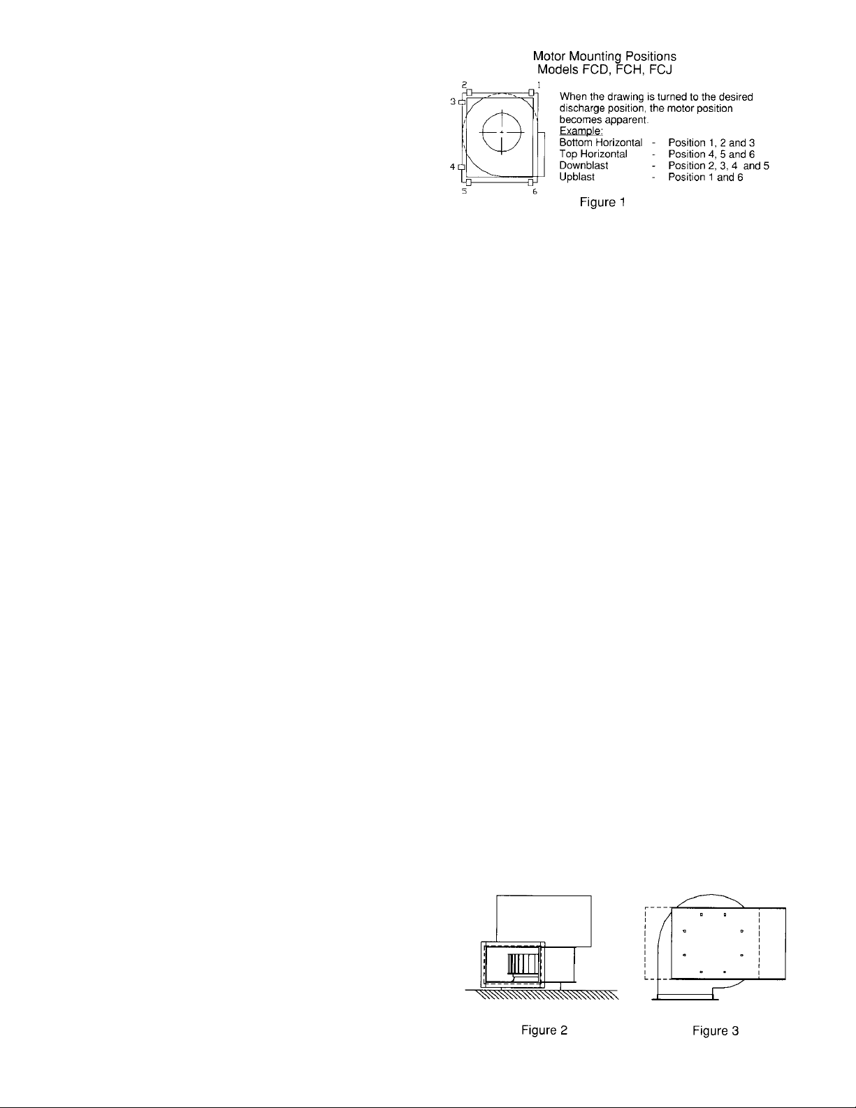
When the motor and drives are received mounted to
the (FCF) fan, the RPM has been set to meet the
specified performance. Motor positions for the FCD,
FCH and FCJ blowers are defined in Figure 1.
For fans shipped without motors and drives mounted,
the RPM is set by the installer as specified. Pulley
combinations and belt lengths are included with each
blower.
2
Page 3

10. WARNING! Do not operate at a static pressure below
that specified. This unit is designed to operate at a
specific static pressure. If operated at a static pressure
below that specified, motor overloading and burn-out
will result. Characteristics of wheel require high
brake horsepower at low static pressure! If the static
pressure is actually less than the designed pressure,
the motor will be operating at a higher BHP. Using an
ammeter, measure the amperes actually being drawn
by the fan motor WITH the duct in place. If the amp
draw is greater than the service factor amperes, reduce
the fan RPM by opening the variable speed drive on the
motor shaft. Check the current again and repeat if
necessary.
MAINTENANCE
1. CAUTION! Before proceeding, make sure the electrical
service to the fan is locked in “OFF” position.
2. REGULAR MAINTENANCE A regularly scheduled
inspection of all fan parts based on the condition of the
air passing through the fan establishes a good
maintenance routine. When the air is clean,
maintenance can be as infrequent as once a year.
When air is contaminated, maintenance may be
required as often as once a month. Regular
maintenance should include inspection and cleaning of
all fan parts.
3. BELT DRIVES Check belt tension after first 48 hours
of operation and thereafter annually. If belts show wear,
they should be replaced. For 2 belt drives, be sure to
replace both belts with a matched set. Do not adjust
belts too tightly as this will cause undue wear on the
bearings of both fan and motor. Motor pulleys should
be inspected regularly and replaced if they show
evidence of excessive wear or “grooving”.
WARNING! Do not operate at higher speeds than rated
in catalog. Do not replace motor pulley with one having
larger diameter or fan pulley with one of smaller
diameter.
4. LUBRICATION .75" (19 mm) and 1.00" (25 mm) ball
bearings are permanently lubricated. 1.19" (30 mm)
and larger bearings are lubricatable. DO NOT OVER
LUBRICATE. Caution should be used when greasing
with a high pressure gun which can blow bearing seals
and overfill the bearing with grease. This condition can
result in excessive overheating of the bearing and
eventual failure. If impeller shaft bearings need
replacement, replace with bearings comparable to
original equipment. To insure correct spacing of new
bearings, measure the distance between old bearings
and distance between bearings and end of shaft.
IMPORTANT: All bearings are of the locking collar
type. The collar must first be positioned against inner
race on inboard bearing and turned in direction of
impeller rotation with drift pin and hammer until it locks.
Locking collars must be on inboard (facing) sides of the
bearings. Secure bearing to shaft with set screw. Lock
and secure other bearing to shaft in same manner.
If pillow block type bearings are used, slide bearings
onto shaft to desired location and bolt bearing block
securely to support base.
5. MOTORS Most motors are pre-lubricated and do not
require additional lubrication. Grease fittings on the
motor indicate the exception and these should be
greased in accordance with printed instructions on the
motor.
PROCEDURE FOR TIGHTENING SET SCREWS
IN BEARINGS AND HUBS
One Set Screw Application
Using a torque wrench, tighten the set screw to the torque
recommended in Table 1.
Two Set Screw Application
1. Using a torque wrench, tighten one set screw to half of
the torque recommended in Table 1.
2. Tighten the second set screw to the full recommended
torque.
3. Tighten the first set screw to the full recommended
torque.
Table 1. Recommended Tightening
Torque for Set Screws
Set Screw Diameter Torque (in-lbs)
#10 35
1/4 80
5/16 126
3/8 240
7/16 384
1/2 744
9/16 1080
5/8 1500
3/4 2580
7/8 3600
1 5400
VARIABLE FREQUENCY
DRIVES AND MOTORS
There are occasions when a Variable Frequency Drive (VFD)
will cause poor motor performance and possible damage.
To avoid these problems, the Company recommends the
following:
1. Select compatible motor and VFD converter; if possible,
the motor and the converter should be from the same
manufacturer or at least the converter selected should
be recommended by the motor manufacturer.
2. A motor shaft grounding system should be used to
prevent motor bearing damage from eddy currents.
Slide shaft back and forth in secured bearing (do not
drive with hammer) and rotate to make certain it turns
freely. Secure bearings to shaft by tightening set
screws.
NOTE: The Company will not honor motor warranty
claims if the customer fails to follow these
recommendations.
3
Page 4

TERMS AND CONDITIONS
DESIGN CHANGES Acme reserves the right to
make changes in design, improvements and
additions in and to its products any time without
imposing any liability or obligations to itself to
apply or install the same in any product manu
factured by it.
TITLE The title and right of possession of the
equipment sold herein shall remain with the
Company and such equipment shall remain
personal property until all payments herein (in
These instructions cover the usual installation, operation and maintenance methods for which the product(s) was designed. They do not purport to
cover all details or variations in the product(s) nor to provide for every possible contingency that might be met in connection with the installation, oper
ation and maintenance. For any departures from these instructions, or should particular problems arise which are not covered sufficiently for the pur
chaser’s purpose, the matter should be referred to the Company.
WARNING Acme products are designed and manufactured to provide reliable performance but they are not guaranteed to be 100% free of defects.
Even reliable products will experience occasional failures and this possibility should be recognized by the User. If these products are used in a life sup
port ventilation system where failure could result in loss or injury, the User should provide adequate back-up ventilation, supplementary natural ventila
tion or failure alarm system, or acknowledge willingness to accept the risk of such loss or injury.
WARNING DO NOT use in HAZARDOUS ENVIRONMENTS where fan’s electrical system could provide ignition to combustible or flammable materials
unless unit is specifically built for hazardous environments.
CAUTION Guards must be installed when fan is within reach of personnel or within seven (7) feet (2.134 m) of working level or when deemed advisable
for safety.
DISCLAIMER The Company has made a diligent effort to illustrate and describe the products in this literature accurately; however, such illustrations and
descriptions are for the sole purpose of identification, and do not express or imply a warranty that the products are merchantable, or fit for a particular
purpose, or that the products will necessarily conform to the illustrations or descriptions or dimensions.
cluding deferred payments whether evidenced
by notes or otherwise) shall have been made in
full in cash and the Purchaser agrees to do all
acts necessary to perfect and maintain such
right and title in the Company.
-
SAFETY ACCESSORIES The Company manu
factures equipment designed to serve multiple
applications and offers a wide range of safety
equipment, including guards and other devices,
as may be required to meet customer specifica
-
tions. Without exception, the Company recom
mends that all orders include applicable safety
devices. Equipment ordered without applicable
safety devices is clearly the responsibility of the
Purchaser. Further, the Purchaser warrants
that he has determined and acquired any and
all safety devices required for equipment sold
by the Company. Weather covers and guards
for motor and V-belt drives, couplings, shafts
and bearings, along with inlet and outlet
screens, are optional accessories noted in the
price list.
-
-
-
-
-
-
WARRANTY AND DISCLAIMER: Acme Engineering and Manufacturing Corporation extends
this limited warranty to the original buyer and
warrants that products supplied by the Company, shall be free from original defects in
workmanship and materials for two years from
date of shipment (except for the warranty periods noted for products in the paragraph immediately following), provided same have been
properly handled, stored, installed, serviced,
maintained and operated. This warranty shall
not apply to products which have been altered
or repaired without the Company’s express au
thorization, or altered or repaired in any way so
as, in the Company’s judgment, to affect its per
formance or reliability, nor which have been im
properly installed or subjected to misuse, negli
gence, or accident, or incorrectly used in com
bination with other substances. Evaporative
cooling pads are warranted to be free of defects
in materials and workmanship for a period of
two years from date of shipment provided same
have been properly handled, stored, installed,
serviced, maintained and operated; and further,
not subjected to excessive heat, corrosive
agents or chemicals, or mechanical abuse that
may cause tearing, crushing or undue deterio
ration, nor used on a system or in a manner
other than that for which it was designed as ex
plained in the product literature. The Buyer as
sumes all risks and liability for results of use of
all products.
Acme’s exclusive duplex split pillow block bear
ings and shaft are warranted to be free of de
fects in materials and workmanship for a period
of five years from date of shipment. Belts are
warranted to be free of defects in materials and
workmanship for a period of one year from date
of shipment. Polyethylene tubing is warranted
to be free of defects in materials and workman
ACME ENGINEERING AND
MANUFACTURING CORPORATION
P.O. Box 978
Muskogee, Oklahoma 74402
Telephone 918/682-7791
Fax 918/682-0134
LIMITED WARRANTY
ship for a period of 90 days from date of shipment.
LIMITATION OF REMEDY AND DAMAGES:
All claims under this warranty must be made in
writing and delivered to P. O. Box 978, Muskogee, Oklahoma, 74402, within 15 days after discovery of the defect and prior to the expiration
of two years from the date of shipment by the
Company of the product claimed defective, and
Buyer shall be barred from any remedy if Buyer
fails to make such claim within such period.
Within 30 days after receipt of a timely claim,
the Company shall have the option either to in
spect the product while in Buyer’s possession
or to request Buyer to return the product to the
Company at Buyer’s expense for inspection by
the Company. The Company shall replace, or
at its option repair, free of charge, any product
it determines to be defective, and it shall ship
the repaired or replacement product to Buyer
F.O.B. point of shipment; provided, however, if
circumstances are such as in the Company’s
judgment to prohibit repair or replacement to
remedy the warranted defects, the Buyer’s sole
and exclusive remedy shall be a refund to the
Buyer of any part of the invoice price, paid to
the Company, for the defective product or part.
-
-
The Company is not responsible for the cost of
removal of the defective product or part, dam
ages due to removal, or any expenses incurred
in shipping the product or part to or from the
Company’s plant, or the installation of the re
paired or replaced product or part.
Implied warranties, when applicable, shall com
mence upon the same date as the express war
ranty provided above, and shall, except for war
ranties of title, extend only for the duration of
-
the express warranty. Some states do not allow
limitations on how long an implied
warranty lasts, so the above limitation
may not apply to you. The only rem
edy provided to you under an applica
ble implied warranty and the express
warranty shall be the remedy pro
vided under the express warranty,
subject to the terms and conditions
contained therein. The Company
shall not be liable for incidental and consequential losses and damages under the express
warranty, any applicable implied warranty, or
claims for negligence, except to the extent that
this limitation is found to be unenforceable under applicable state law. Some states do not allow the exclusion or limitation of incidental or
consequential damages, so the above limitation
or exclusion may not apply to you. This warranty gives you specific legal rights, and you
may also have other rights which vary from
state to state.
No employee, agent, dealer, or other person is
-
authorized to give any warranties on behalf of
the Company or to assume for the Company
any other liability in connection with any of its
products except in writing and signed by an offi
cer of the Company.
REPLACEMENT PARTS If replacement parts
are ordered, buyer warrants that the original
components in which these replacement parts
will be placed are in satisfactory working condi
tion, and when said replacement parts are in
stalled, the resultant installation will operate in
a safe manner, at speeds and temperatures for
which the original equipment was purchased.
TECHNICAL ADVICE AND RECOMMENDA
TIONS, DISCLAIMER: Notwithstanding any
past practice or dealings or any custom of the
trade, sales shall not include the furnishing of
technical advice or assistance or system de
sign. Any such assistance shall be at the Com
pany’s sole option and may be subject to addi
tional charge.
The Company assumes no obligation or liability
on account of any recommendations, opinions
or advice as to the choice, installation or use of
products. Any such recommendations, opinions
or advice are given and shall be accepted at
your own risk and shall not constitute any war
ranty or guarantee of such products or their
performance.
-
GENERAL In no event shall any claim for con
sequential damages be made by either party.
The Company will comply with all applicable
Federal, State, and local laws.
-
-
-
-
-
-
-
-
-
Member Air Movement and Control Association August 2002 Form 610032
 Loading...