

Page 1
Page 2
Acme Engineering & Manufacturing Corporation
Page 2
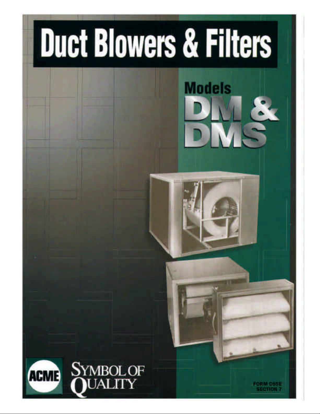
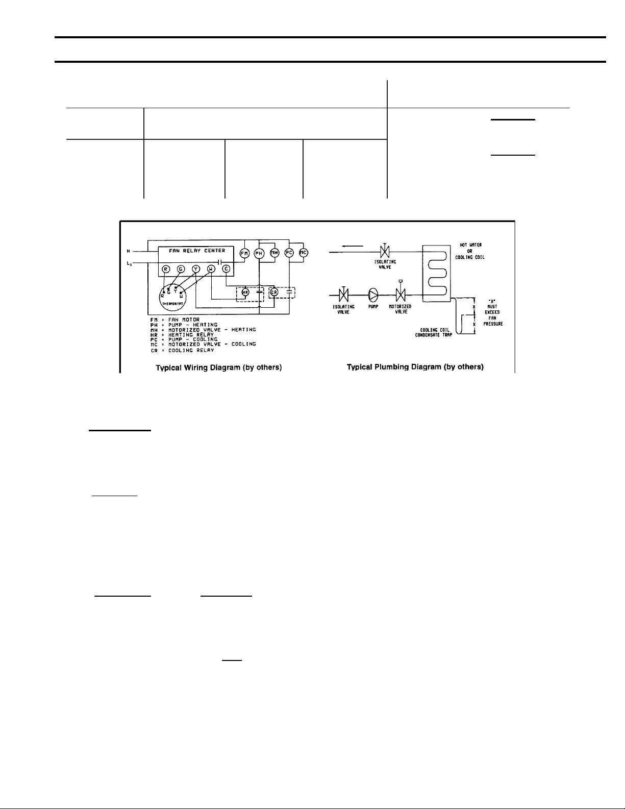
DM CONSTRUCTION FEATURES
ACME DUCTMASTER
™
SINGLE & TWIN DUCT
BLOWERS DM SERIES
FOR INDOOR USE ONLY
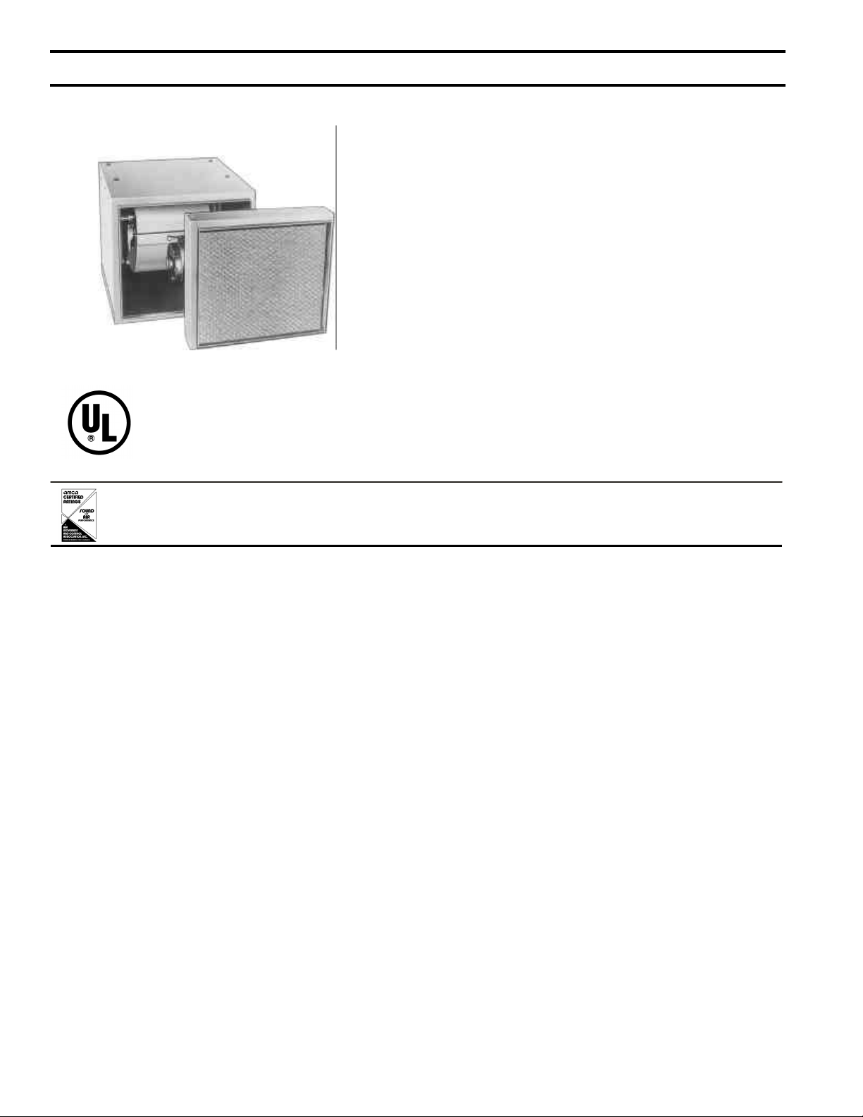
An all-purpose CABINET BLOWER with a compact optional FILTER
SECTION.
Widely used in conjunction with HEATING, COOLING and
VENTILATING systems.
(Shown with Optional Series F200A Filter Section)
Acme certifies that the DM Series Duct Blower shown hereon is licensed to bear the AMCA Seal. The ratings shown are based on tests
and procedures performed in accordance with AMCA Publication 211 and Publication 311 and comply wit h the requirements of the AMCA
Certified Ratings Program.
An economical, quiet and efficient solution for many air moving
requirements.
Available with 7”, 9”, 10”, 12”, 15” and 18” blower.
CONSTRUCTION FEATURES
• Blower is equipped with ball bearings which have an
operating temperature range of -65º to +250ºF.
• 9/16” mounting holes are provided in the top of
cabinet for support rods when unit is suspended
overhead.
• Hook bolt motor mounting allows 7” through 12”
models, single and twin units, to be used in the
up-flow, down-flow and horizontal flow discharge
positions.
• Heavy duty motor mounting brackets with motor
adjusting bolt and rubber bumper is supplied on 15”
and 18” models. Suitable for horizontal position
only.
• Access panels on both sides allow easy servicing to
blower and motor.
• Keywayed shafts are standard on both ends.
• Blower is rubber mounted for quiet operation.
• Twin Duct Blowers are tied together with steel
angle runners. Twin blowers are on a common
shaft and driven from either end.
OPTIONAL ACCESSORIES
• SERIES HC HOT WATER HEATING COILS
attach to blower inlet. Two row aluminum fin
copper tube with sloped drain pan for positive
condensate removal.
• SERIES CW CHILLED WATER COOLING
COILS attach to blower inlet. Four row
aluminum fin copper tube with sloped drain pan
for positive condensate removal.
• SERIES F200A FILTER SECTIONS are
insulated and supplied with 1” framed aluminum
mesh filter. All filter racks will accommodate
either 1” or 2” filter. Easily removed for servicing
through end access panel.
Page 3
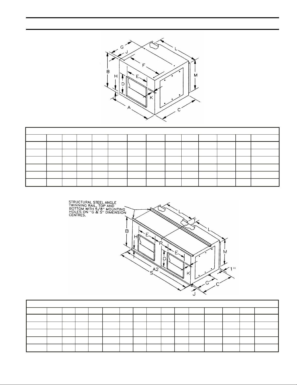
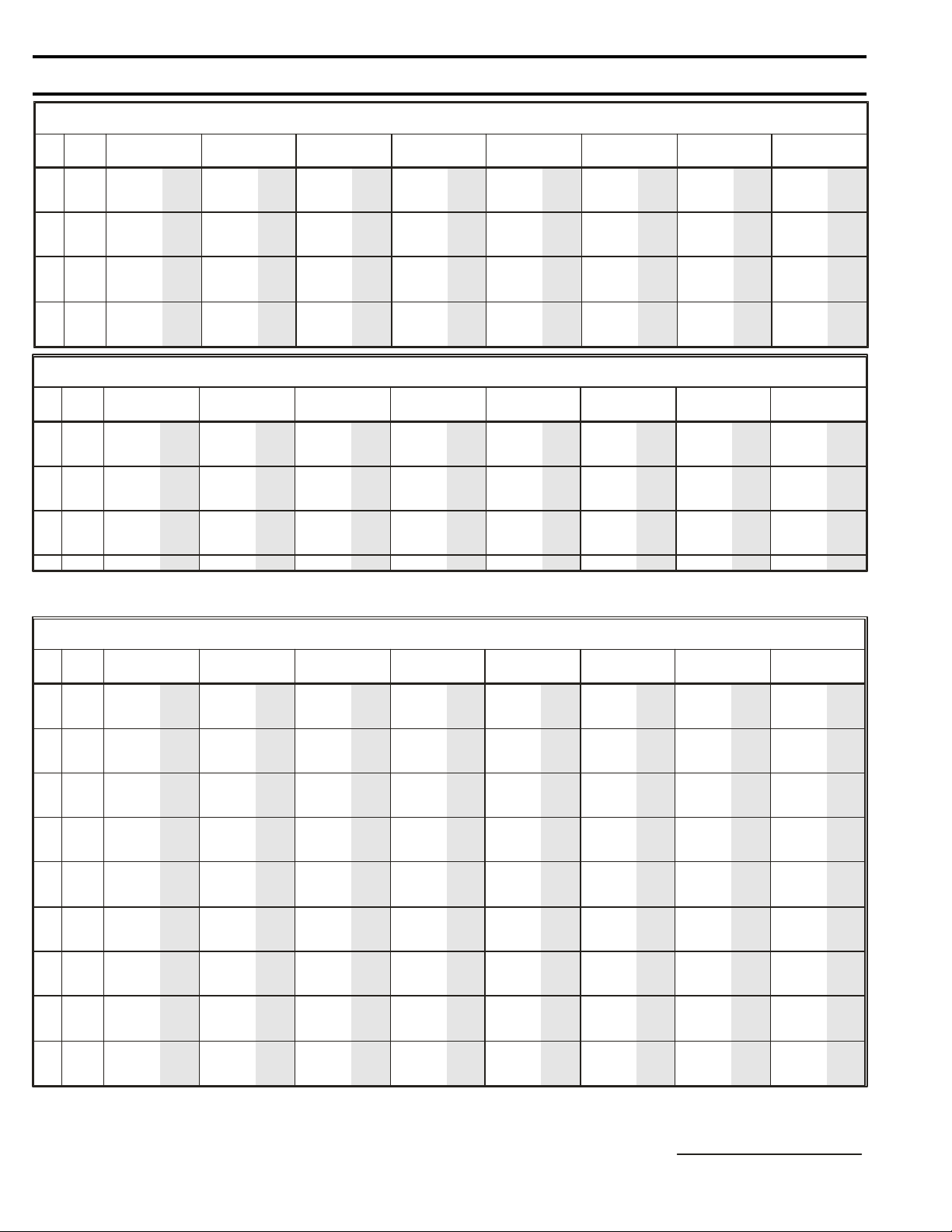
DM DIMENSIONAL DATA
Page 3 Acme Engineering & Manufacturing Corporation
These are typical drawings for dimensional purposes only.
They are correct within limits suitable for normal installation
requirements and do not necessarily show actual construction.
DUCT BLOWER - SINGLE (in.)
MODEL A B C D E F G H J K L M wt. lbs.
DM07 18 15-3/8 23 8-1/4 9-3/16 14-1/2 9-5/8 1-1/4 1-1/4 7/8 15-7/8 13-3/8 46
DM09 21 18 23 10-1/4 11-13/16 17-1/2 11-3/4 1-1/4 1-3/4 7/8 19 16 58
DM10 22-1/4 20 24-3/4 11-3/8 13-1/8 18-3/4 13-3/8 1-1/4 1-1/4 7/8 20-1/4 18 69
DM12 27 23 27-1/2 13-7/16 15-5/8 23-1/2 16-1/8 1-1/4 1-1/4 7/8 25 21 89
DM15 33-1/2 28 32 15-7/8 18-5/8 28 19-1/2 2-5/8 1-1/4 7/8 30-1/2 25 175
DM18 41-1/2 34 44 19-5/8 22-5/8 35 24 2-3/4 1-3/4 1-1/8 35-3/8 31-5/8 205
Note: Weight is less motor and drive.
These are typical drawings for dimensional purposes only. They are
correct within limits suitable for normal installation requirements and
do not necessarily show actual construction.
DUCT BLOWER - TWIN (in.)
MODEL A2 B C D E G H J K L M R S T wt. lbs.
DM-T07 36 15-3/8 23 8-1/4 9-3/16 9-5/8 1-1/4 1-1/4 7/8 15-7/8 13-3/8 8-13/16 38-1/4 2 145
DM-T09 42 18 23 10-1/4 11-13/16 11-3/4 1-1/4 1-3/4 7/8 19 16 9-3/16 44-1/4 2 163
DM-T10 44-1/2 20 24-3/4 11-3/8 13-1/8 13-3/8 1-1/4 1-3/4 7/8 20-1/4 18 9-1/8 46-3/4 2 190
DM-T12 54 23 27-1/2 13-7/16 15-5/8 16-1/8 1-1/4 1-3/4 7/8 25 21 11-3/8 56-1/4 2 240
DM-T15 67 28 32 15-7/8 18-5/8 19-1/2 2-5/8 1-3/4 7/8 30-1/2 25 14-7/8 69-1/4 3 345
Note: Weight is less motor and drive.
Page 4
PERFORMANCE DATA
Acme Engineering & Manufacturing Corporation
Page 4
MODEL DM07 3/4 HP MAXIMUM TIP SPEED = 2.03 x RPM
OUTLET
VELOCITY
CFM FPM RPM BHP SONES RPM BHP SONES RPM BHP SONES RPM BHP SONES RPM BHP SONES RPM BHP SONES RPM BHP SONES RPM BHP SONES
300 569 526 0.01 1.3 719 0.03 -- 1026 0.06 -- 1247 0.09 -- 1433 0.12 -- 1733 0.19 -- 1980 0.26 -- 2189 0.33 -400 759 567 0.02 1.8 737 0.04 3.9 1019 0.07 -- 1257 0.11 -- 1448 0.15 -- 1761 0.24 -- 2020 0.33 -- 2242 0.42 -500 949 636 0.04 3.1 770 0.05 4.2 1027 0.09 9.3 1246 0.13 -- 1450 0.18 -- 1775 0.28 -- 2038 0.39 -- 2271 0.50 -600 1139 719 0.06 4.3 822 0.07 6.2 1051 0.12 10.1 1255 0.16 11.8 1437 0.20 -- 1777 0.32 -- 2051 0.45 -- 2286 0.58 -700 1329 806 0.08 6.4 894 0.10 8.7 1086 0.15 10.8 1278 0.20 12.5 1451 0.24 14.3 1763 0.35 22 2052 0.50 -- 2295 0.65 -800 1519 894 0.12 8.6 975 0.14 10.1 1134 0.18 11.7 1308 0.24 12.9 1473 0.30 15.7 1768 0.41 23 2038 0.54 -- 2292 0.71 --
900 1709 983 0.16 10.8 1062 0.19 12.1 1198 0.23 12.9 1350 0.29 13.8 1503 0.36 20.7 1785 0.48 24 2038 0.61 -- -- -- -1000 1899 1073 0.21 12.6 1149 0.24 13.3 1272 0.29 14.7 1400 0.35 15.1 1540 0.43 17.6 1809 0.57 26 2053 0.70 -- -- -- -1100 2089 1165 0.27 14.1 1236 0.31 14.8 1352 0.37 15.6 1465 0.43 17.7 1588 0.50 19.8 1840 0.66 29 -- -- -- -- -- -1200 2279 1257 0.35 15.8 1325 0.39 16.5 1438 0.46 17.6 1539 0.52 23 1644 0.58 23 -- -- -- -- -- -- -- -- -1300 2469 1351 0.43 17.9 1414 0.48 18.5 1526 0.56 21 1618 0.62 37 1713 0.69 27 -- -- -- -- -- -- -- -- -1400 2659 1445 0.53 22 1505 0.59 22 1613 0.67 24 1701 0.74 26 -- -- -- -- -- -- -- -- -- -- -- --
1/8” SP 1/4” SP 1/2” SP 3/4” SP 1” SP 1-1/2” SP 2” SP 2-1/2” SP
MODEL DM-T07 1-1/2 HP MAXIMUM TIP SPEED EQUALS = 2.03 x RPM
OUTLET
VELOCITY
CFM FPM RPM BHP SONES RPM BHP SONES RPM BHP SONES RPM BHP SONES RPM BHP SONES RPM BHP SONES RPM BHP SONES RPM BHP SONES
600 569 526 0.03 1.9 719 0.05 3.8 1026 0.11 11.1 1247 0.18 -- 1433 0.24 -- 1733 0.38 -- 1980 0.51 -- 2189 0.67 --
800 759 567 0.05 2.5 737 0.07 4.9 1019 0.14 10.8 1257 0.22 14.1 1448 0.30 16.8 1761 0.48 27 2020 0.65 -- 2242 0.83 -1000 949 636 0.07 3.9 770 0.11 5.3 1027 0.18 11.2 1246 0.25 13.7 1450 0.36 17.0 1775 0.57 28 2038 0.79 -- 2271 1.00 -1200 1139 719 0.11 5.3 822 0.15 7.6 1051 0.23 12.1 1255 0.31 14.0 1437 0.40 16.3 1777 0.64 28 2051 0.90 -- 2286 1.16 -1400 1329 806 0.17 7.9 894 0.20 10.5 1086 0.30 12.9 1278 0.39 15.0 1451 0.49 17.1 1763 0.71 27 2052 1.00 -- 2295 1.29 -1600 1519 894 0.24 10.6 975 0.28 12.1 1134 0.37 14.0 1308 0.49 15.4 1473 0.60 18.8 1768 0.82 28 2038 1.08 -- 2292 1.42 -1800 1709 983 0.32 13.0 1062 0.37 14.5 1198 0.47 15.5 1350 0.59 16.5 1503 0.72 25 1785 0.97 29 2038 1.22 -- -- -- -2000 1899 1073 0.43 15.1 1149 0.49 16.0 1272 0.59 17.6 1400 0.70 18.1 1540 0.85 21 1809 1.13 32 2053 1.40 -- -- -- -2200 2089 1165 0.55 16.8 1236 0.63 17.7 1352 0.74 18.7 1465 0.85 21 1588 1.00 24 1840 1.32 35 -- -- -- -- -- -2400 2279 1257 0.70 18.9 1325 0.79 19.7 1438 0.91 21 1539 1.03 28 1644 1.17 28 -- -- -- -- -- -- -- -- -2600 2469 1351 0.87 21 1414 0.97 22 1526 1.12 25 1618 1.24 -- 1713 1.38 33 -- -- -- -- -- -- -- -- -2800 2659 1445 1.07 26 1505 1.17 27 1613 1.35 29 1701 1.49 -- -- -- -- -- -- -- -- -- -- -- -- --
1/8” SP 1/4” SP 1/2” SP 3/4” SP 1” SP 1-1/2” SP 2” SP 2-1/2” SP
3/4” SHAFT WHEEL DIA. = 7.75”
3/4” SHAFT WHEEL DIA. = 7.75”
MODEL DM09 3/4 HP MAXIMUM TIP SPEED = 2.65 x RPM
OUTLET
VELOCITY
CFM FPM RPM BHP SONES RPM BHP SONES RPM BHP SONES RPM BHP SONES RPM BHP SONES RPM BHP SONES RPM BHP SONES RPM BHP SONES
600 713 417 0.03 1.6 557 0.05 2.2 798 0.10 5.7 977 0.15 8.5 1120 0.21 10.8 1353 0.33 -- 1548 0.45 -- 1717 0.59 -700 832 440 0.04 1.3 566 0.06 2.5 791 0.11 5.4 979 0.17 8.6 1128 0.23 11.1 1367 0.37 -- 1564 0.50 -- 1736 0.65 -800 951 468 0.06 1.8 581 0.07 3.8 786 0.12 5.2 974 0.19 8.4 1130 0.26 11.2 1379 0.41 15.8 1578 0.56 -- 1751 0.72 --
900 1070 499 0.07 2.2 601 0.10 3.1 792 0.14 5.5 964 0.21 8.1 1126 0.28 11.0 1384 0.45 16.2 1590 0.61 19.7 -- -- -1000 1189 534 0.09 2.7 625 0.12 4.1 802 0.17 5.8 964 0.23 8.1 1118 0.31 10.7 1384 0.48 16.2 1596 0.67 20 -- -- -1100 1308 573 0.12 3.4 653 0.15 6.9 816 0.20 6.7 970 0.27 8.3 1112 0.34 10.5 1379 0.52 15.8 1598 0.72 20 -- -- -1200 1427 613 0.15 4.5 682 0.18 10.3 834 0.24 8.0 979 0.30 8.6 1115 0.38 10.6 1371 0.56 15.3 -- -- -- -- -- -1300 1546 654 0.19 6.1 714 0.22 5.2 856 0.28 7.0 992 0.35 8.9 1122 0.42 10.9 1362 0.60 14.8 -- -- -- -- -- -1400 1665 696 0.23 7.0 750 0.26 5.9 881 0.33 7.6 1009 0.40 9.4 1132 0.48 11.3 1362 0.65 14.8 -- -- -- -- -- -1500 1783 739 0.28 7.7 788 0.31 6.7 907 0.38 8.2 1028 0.46 10.1 1145 0.53 11.9 1367 0.71 15.1 -- -- -- -- -- -1600 1902 782 0.34 8.3 828 0.37 7.5 936 0.44 8.9 1050 0.52 10.4 1162 0.60 13.6 -- -- -- -- -- -- -- -- -1700 2021 826 0.40 8.8 868 0.43 8.3 966 0.51 9.6 1075 0.59 11.1 1181 0.68 17.5 -- -- -- -- -- -- -- -- --
1/8” SP 1/4” SP 1/2” SP 3/4” SP 1” SP 1-1/2” SP 2” SP 2-1/2” SP
3/4” SHAFT WHEEL DIA. = 10.13”
Performance shown is for installation Type B - Free inlet, Ducted outlet, without filter section. Power rating (BHP) does not include drive losses.
Performance ratings do not include the effects of appurtenances in the airstream. The sound ratings shown are loudness values in fan sones at 5 ft. (1.5m) in a
hemispherical free field calculated per AMCA Standard 301. Values shown are for Installation Type B: free inlet fan sone levels. Sone values not documented in unlisted
areas. Twin unit data is derived from tests of single width fans.
SI CONVERSION FACTOR
CFM x .472 = L/s SP x .249 = kPa
Page 5
PERFORMANCE DATA
Acme Engineering & Manufacturing Corporation
MODEL DM-T09 1-1/2 HP MAXIMUM TIP SPEED = 2.65 x RPM
OUTLET
VELOCITY
FPM RPM BHP SONES RPM BHP SONES RPM BHP SONES RPM BHP SONES RPM BHP SONES RPM BHP SONES RPM BHP SONES RPM BHP SONES
CFM
1200 713 417 0.06 2.3 557 0.09 2.9 798 0.19 6.8 977 0.30 10.3 1120 0.41 13.0 1353 0.65 -- 1548 0.90 -- 1717 1.17 -1400 832 440 0.08 1.8 566 0.12 3.0 791 0.22 6.6 979 0.34 10.3 1128 0.47 13.4 1367 0.73 -- 1564 1.01 -- 1736 1.30 -1600 951 468 0.11 2.4 581 0.15 3.8 786 0.25 6.4 974 0.37 10.2 1130 0.52 13.5 1379 0.81 18.9 1578 1.12 -- 1751 1.43 -1800 1070 499 0.14 2.9 601 0.19 3.9 792 0.29 6.6 964 0.41 9.8 1126 0.56 13.3 1384 0.89 19.3 1590 1.23 24 -- -- -2000 1189 534 0.19 3.5 625 0.24 5.0 802 0.34 7.0 964 0.47 9.8 1118 0.62 12.9 1384 0.97 19.3 1596 1.33 24 -- -- -2200 1308 573 0.24 4.3 653 0.29 8.5 816 0.40 8.1 970 0.53 10.0 1112 0.68 12.6 1379 1.03 18.9 1598 1.44 24 -- -- -2400 1427 613 0.30 5.6 682 0.36 12.4 834 0.48 9.7 979 0.61 10.3 1115 0.76 12.7 1371 1.11 18.3 -- -- -- -- -- -2600 1546 654 0.38 7.4 714 0.43 6.3 856 0.56 8.4 992 0.69 10.8 1122 0.85 13.1 1362 1.20 17.7 -- -- -- -- -- -2800 1665 696 0.46 8.4 750 0.52 7.1 881 0.66 9.2 1009 0.80 11.4 1132 0.95 13.6 1362 1.31 17.8 -- -- -- -- -- -3000 1783 739 0.56 9.4 788 0.62 8.1 907 0.77 9.9 1028 0.92 12.1 1145 1.06 14.4 1367 1.43 18.1 -- -- -- -- -- -3200 1902 782 0.67 10.1 828 0.73 9.0 936 0.88 10.8 1050 1.05 12.5 1162 1.20 16.3 -- -- -- -- -- -- -- -- -3400 2021 826 0.80 10.6 868 0.86 10.0 966 1.02 11.5 1075 1.19 13.5 1181 1.36 21 -- -- -- -- -- -- -- -- --
1/8” SP 1/4” SP 1/2” SP 3/4” SP 1” SP 1-1/2” SP 2” SP 2-1/2” SP
MODEL DM10 1-1/2 HP MAXIMUM TIP SPEED = 2.99 x RPM
OUTLET
VELOCITY
CFM FPM RPM BHP SONES RPM BHP SONES RPM BHP SONES RPM BHP SONES RPM BHP SONES RPM BHP SONES RPM BHP SONES RPM BHP SONES
800 771 388 0.04 2.0 511 0.07 3.1 709 0.12 5.9 861 0.18 8.8 987 0.25 -- 1196 0.41 -- 1371 0.58 -- 1524 0.76 --
900 868 403 0.05 2.5 520 0.08 3.7 712 0.14 6.0 866 0.21 9.0 993 0.27 11.8 1204 0.44 -- 1380 062 -- 1533 0.81 -1000 964 422 0.06 2.4 531 0.09 4.6 713 0.15 6.1 869 0.23 9.1 998 0.31 12.0 1210 0.47 -- 1387 0.66 -- 1542 0.87 -1100 1060 445 0.08 3.0 544 0.11 6.0 719 0.18 6.3 872 0.26 9.2 1002 0.34 12.2 1216 0.50 16.7 1394 0.70 -- 1550 0.92 -1200 1157 470 0.10 3.8 559 0.13 8.7 728 0.20 6.8 873 0.28 9.3 1005 0.37 12.4 1221 0.55 17.0 1400 0.74 21 1557 0.97 -1300 1253 497 0.12 5.4 575 0.15 4.6 738 0.23 7.2 878 0.31 9.5 1007 0.40 12.5 1225 0.61 17.2 1405 0.79 21 1563 1.02 -1400 1350 525 0.15 4.9 593 0.18 5.3 749 0.26 7.8 886 0.34 9.9 1009 0.43 12.6 1229 0.65 17.4 1410 0.86 21 1568 1.07 25
1500 1446 553 0.18 5.6 616 0.21 6.5 762 0.29 8.4 895 0.38 10.3 1013 0.47 12.8 1232 0.70 17.6 1415 0.93 22 1573 1.14 26
1600 1543 582 0.22 6.7 640 0.25 8.0 776 0.33 9.0 905 0.42 10.8 1021 0.52 13.2 1234 0.74 17.7 1419 1.00 22 1578 1.23 26
1700 1639 612 0.25 7.8 666 0.29 9.6 791 0.37 9.6 916 0.46 11.3 1030 0.57 13.7 1235 0.79 17.8 1422 1.06 22 1583 1.32 27
1800 1736 642 0.29 8.8 693 0.33 11.0 807 0.41 10.2 928 0.51 11.9 1040 0.62 14.3 1239 0.84 18.0 1424 1.12 22 1587 1.40 27
1900 1832 672 0.34 9.7 720 0.38 12.1 824 0.46 10.4 942 0.56 12.6 1051 0.68 14.9 1246 0.91 18.4 1426 1.17 22 1590 1.48 27
1/8” SP 1/4” SP 1/2” SP 3/4” SP 1” SP 1-1/2” SP 2” SP 2-1/2” SP
3/4” SHAFT WHEEL DIA. = 10.13”
3/4” SHAFT WHEEL DIA. = 11.44”
MODEL DM-T10 1-1/2 HP MAXIMUM TIP SPEED = 2.99 x RPM
OUTLET
VELOCIT Y
CFM FPM RPM BHP SONES RPM BHP SONES RPM BHP SONES RPM BHP SONES RPM BHP SONES RPM BHP SONES RPM BHP SONES RPM BHP SONES
1600 771 388 0.08 2.7 511 0.13 3.9 709 0.25 7.2 861 0.36 10.7 987 0.51 -- 1196 0.82 -- 1371 1.16 -- -- -- -1800 868 403 0.10 3.2 520 0.16 4.6 712 0.28 7.3 886 0.42 11.0 993 0.55 14.3 1204 0.88 -- 1380 1.24 -- -- -- -2000 964 422 0.13 3.1 531 0.18 5.6 713 0.31 7.4 869 0.47 11.1 998 0.61 14.5 1210 0.94 -- 1387 1.32 -- -- -- -2200 1060 445 0.16 3.7 544 0.22 7.3 719 0.35 7.7 872 0.51 11.3 1002 0.69 14.8 1216 1.00 20 1394 1.40 -- -- -- -2400 1157 470 0.20 4.7 559 0.26 10.6 728 0.40 8.2 873 0.55 11.4 1005 0.75 15.0 1221 1.10 20 1400 1.49 -- -- -- -2600 1253 497 0.25 6.6 575 0.30 5.7 738 0.45 8.8 878 0.61 11.7 1007 0.80 15.1 1225 1.21 21 -- -- -- -- -- -2800 1350 525 0.30 6.0 593 0.35 6.5 749 0.51 9.4 886 0.69 12.1 1009 0.86 15.2 1229 1.31 21 -- -- -- -- -- -3000 1446 553 0.36 6.8 616 0.42 7.9 762 0.58 10.1 895 0.76 12.6 1013 0.95 15.4 1232 1.40 21 -- -- -- -- -- -3200 1543 582 0.43 8.0 640 0.49 9.7 776 0.65 10.9 905 0.84 13.1 1021 1.04 15.8 1234 1.48 21 -- -- -- -- -- -3400 1639 612 0.51 9.3 666 0.57 11.5 791 0.73 11.6 916 0.93 13.7 1030 1.14 16.4 -- -- -- -- -- -- -- -- -3600 1736 642 0.59 10.6 693 0.66 13.3 807 0.82 12.4 928 1.02 14.4 1040 1.25 17.0 -- -- -- -- -- -- -- -- -3800 1832 672 0.68 11.7 720 0.77 14.5 824 0.91 12.7 942 1.13 15.2 1051 1.35 17.8 -- -- -- -- -- -- -- -- --
1/8” SP 1/4” SP 1/2” SP 3/4” SP 1” SP 1-1/2” SP 2” SP 2-1/2” SP
3/4” SHAFT WHEEL DIA. = 11.44”
Performance shown is for installation Type B - Free inlet, Ducted outlet, without filter section. Power rating (BHP) does not include drive losses.
Performance ratings do not include the effects of appurtenances in the airstream. The sound ratings shown are loudness values in fan sones at 5 ft. (1.5m) in a
hemispherical free field calculated per AMCA Standard 301. Values shown are for Installation Type B: free inlet fan sone levels. Sone values not documented in unlisted
areas. Twin unit data is derived from tests of single width fans.
SI CONVERSION FACTOR
CFM x .472 = L/s SP x .249 = kPa
Page 5
Page 6
PERFORMANCE DATA
MODEL DM12 1-1/2 HP MAXIMUM TIP SPEED = 3.27 x RPM
OUTLET
VELOCITY
CFM FPM RPM BHP SONES RPM BHP SONES RPM BHP SONES RPM BHP SONES RPM BHP SONES RPM BHP SONES RPM BHP SONES RPM BHP SONES
1200 823 367 0.07 2.0 470 0.10 3.4 639 0.17 -- 783 0.27 -- 904 0.37 -- 1098 0.57 -- 1255 0.78 -- 1390 1.02 -1400 960 393 0.09 2.8 487 0.13 4.0 646 0.21 -- 783 0.31 -- 904 0.42 -- 1106 0.65 -- 1268 0.89 -- 1407 1.13 -1600 1097 423 0.12 4.1 507 0.17 5.0 658 0.26 10.8 786 0.35 -- 905 0.47 -- 1106 0.72 -- 1276 0.99 -- 1420 1.27 -1800 1234 455 0.16 6.2 532 0.21 6.4 673 0.31 9.3 796 0.41 10.5 906 0.53 -- 1108 0.80 -- 1278 1.08 -- 1427 1.39 -2000 1371 489 0.21 5.1 559 0.26 7.7 690 0.37 9.9 809 0.49 10.4 915 0.61 -- 1108 0.88 -- 1279 1.19 -- -- -- -2200 1508 524 0.27 6.0 588 0.33 9.0 711 0.44 10.6 824 0.57 11.0 927 0.69 13.5 1109 0.97 -- 1279 1.29 -- -- -- -2400 1646 562 0.35 7.3 620 0.40 10.0 734 0.53 11.4 840 0.66 11.7 941 0.79 14.0 1118 1.08 -- 1278 1.40 -- -- -- -2600 1783 601 0.43 8.4 653 0.49 10.7 759 0.62 12.3 860 0.76 12.6 956 0.90 14.6 1129 1.21 -- -- -- -- -- -- -2800 1920 640 0.53 9.3 687 0.59 9.8 786 0.73 13.1 882 0.88 13.5 973 1.03 15.2 1142 1.35 18.3 -- -- -- -- -- -3000 2057 680 0.65 10.3 722 0.70 11.0 815 0.85 14.0 906 1.01 14.6 993 1.17 16.0 -- -- -- -- -- -- -- -- -3200 2194 721 0.78 11.5 758 0.83 12.3 846 0.99 15.0 932 1.16 16.1 1015 1.33 17.1 -- -- -- -- -- -- -- -- -3400 2331 762 0.92 12.9 796 0.98 13.4 877 1.14 16.0 959 1.32 18.4 1039 1.50 19.1 -- -- -- -- -- -- -- -- --
1/8” SP 1/4” SP 1/2” SP 3/4” SP 1” SP 1-1/2” SP 2” SP 2-1/2” SP
MODEL DM-T12 1-1/2 HP MAXIMUM TIP SPEED = 3.27 x RPM
OUTLET
VELOCITY
CFM FPM RPM BHP SONES RPM BHP SONES RPM BHP SONES RPM BHP SONES RPM BHP SONES RPM BHP SONES RPM BHP SONES RPM BHP SONES
2400 823 367 0.13 2.7 470 0.20 4.2 639 0.35 -- 783 0.54 -- 904 0.73 -- 1098 1.15 -- -- -- -- -- -- -2800 960 393 0.18 3.5 487 0.26 5.0 646 0.42 -- 783 0.61 -- 904 0.83 -- 1106 1.30 -- -- -- -- -- -- -3200 1097 423 0.25 5.0 507 0.33 6.2 658 0.51 8.0 786 0.71 -- 905 0.94 -- 1106 1.43 -- -- -- -- -- -- -3600 1234 455 0.33 7.5 532 0.42 7.8 673 0.62 8.7 796 0.83 12.7 906 1.06 -- -- -- -- -- -- -- -4000 1371 489 0.43 6.2 559 0.53 9.4 690 0.74 9.5 809 0.97 12.6 915 1.21 -- -- -- -- -- -- -- -- -- -4400 1508 524 0.54 7.3 588 0.65 10.7 711 0.89 10.4 824 1.13 13.4 927 1.38 16.1 -- -- -- -- -- -- -- -- -4800 1646 582 0.69 8.7 620 0.80 12.0 734 1.06 11.5 840 1.31 14.2 -- -- -- -- -- -- -- -- -- -- -- -5200 1783 601 0.86 10.1 653 0.98 12.9 759 1.25 12.6 -- -- -- -- -- -- -- -- -- -- -- -- -- -- -5600 1920 640 1.06 11.3 687 1.18 12.0 786 1.46 13.9 -- -- -- -- -- -- -- -- -- -- -- -- -- -6000 2057 680 1.29 12.6 722 1.40 13.4 -- -- -- -- -- -- -- -- -- -- -- -- -- -- -- -- -- --
1/8” SP 1/4” SP 1/2” SP 3/4” SP 1” SP 1-1/2” SP 2” SP 2-1/2” SP
3/4” SHAFT WHEEL DIA. = 12.50”
3/4” SHAFT WHEEL DIA. = 12.50”
MODEL DM15 3 HP MAXIMUM TIP SPEED = 3.99 x RPM
OUTLET
VELOCITY
CFM FPM RPM BHP SONES RPM BHP SONES RPM BHP SONES RPM BHP SONES RPM BHP SONES RPM BHP SONES RPM BHP SONES RPM BHP SONES
1800 876 273 0.10 2.7 370 0.18 4.8 510 0.29 8.8 617 0.42 11.3 705 0.57 14.1 850 0.88 18.3 969 1.20 21 1071 1.52 24
1900 925 278 0.11 3.4 373 0.19 5.0 510 0.32 9.0 620 0.44 11.5 708 0.60 14.3 854 0.93 18.6 974 1.26 22 1077 1.59 25
2000 974 284 0.12 4.2 375 0.20 4.5 510 0.35 9.0 622 0.47 11.7 711 0.62 14.6 857 0.97 19.0 978 1.32 22 1083 1.67 25
2100 1022 290 0.14 2.9 375 0.21 4.6 510 0.38 9.0 623 0.50 11.8 714 0.65 14.9 860 1.01 19.3 982 1.37 22 1088 1.74 26
2200 1071 297 0.15 3.5 376 0.22 4.6 511 0.41 9.2 624 0.54 11.9 716 0.68 15.1 863 1.05 19.7 986 1.43 23 1092 1.81 27
2300 1120 305 0.17 4.2 378 0.23 4.7 514 0.44 10.0 624 0.58 11.9 718 0.72 15.3 866 1.09 20 989 1.48 23 1096 1.89 27
2400 1168 314 0.19 4.8 381 0.25 4.8 517 0.46 10.8 624 0.62 12.0 720 0.76 15.5 869 1.13 20 992 1.54 24 1100 1.96 27
2500 1217 323 0.21 5.5 385 0.27 5.1 521 0.49 12.0 624 0.67 12.0 721 0.81 15.5 872 1.17 21 995 1.59 24 1104 2.02 28
2600 1266 332 0.23 4.6 389 0.29 5.3 525 0.51 13.3 625 0.71 12.1 721 0.86 15.5 875 1.21 21 999 1.64 25 1107 2.09 29
2700 1314 342 0.26 5.1 394 0.32 5.6 528 0.54 14.3 626 0.76 12.2 721 0.92 15.5 877 1.26 22 1002 1.69 25 1110 2.16 29
2800 1363 352 0.29 5.6 400 0.34 5.9 530 0.56 9.0 629 0.80 12.6 721 0.98 15.5 879 1.31 22 1005 1.75 25 1113 2.22 29
2900 1412 363 0.31 6.0 406 0.37 6.2 531 0.58 9.1 632 0.84 13.0 721 1.04 15.5 881 1.37 23 1007 1.81 26 1116 2.29 29
3000 1461 373 0.35 6.4 413 0.40 6.5 531 0.60 9.2 636 0.87 13.8 722 1.09 15.6 882 1.44 23 1010 1.87 26 1119 2.36 30
3100 1509 384 0.38 6.7 420 0.43 7.1 532 0.62 9.2 640 0.91 14.5 723 1.15 15.8 883 1.51 23 1012 1.93 27 1122 2.42 30
3200 1558 394 0.42 7.0 427 0.46 8.8 533 0.65 9.3 643 0.95 15.0 725 1.21 15.9 883 1.59 23 1015 2.00 27 1125 2.49 31
3300 1607 405 0.45 7.2 436 0.50 10.3 536 0.68 9.5 646 0.98 15.6 728 1.26 16.2 883 1.68 23 1016 2.07 27 1128 2.57 32
3400 1655 416 0.49 7.4 445 0.54 12.0 539 0.71 9.7 649 1.01 13.6 732 1.31 16.6 883 1.77 23 1018 2.16 28 1130 2.64 32
3500 1704 427 0.54 7.8 454 0.58 14.1 543 0.75 10.0 650 1.04 13.7 736 1.36 16.9 883 1.86 23 1019 2.25 28 1133 2.73 32
3600 1753 437 0.58 8.3 463 0.62 16.4 547 0.80 10.7 651 1.08 13.8 740 1.41 17.3 883 1.94 23 1019 2.35 28 1135 2.81 32
3700 1801 448 0.63 8.8 473 0.67 9.4 552 0.84 11.6 651 1.10 13.8 743 1.46 17.5 884 2.03 24 1020 2.46 28 1137 2.91 33
3800 1850 459 0.68 9.4 483 0.72 10.0 557 0.89 12.5 652 1.14 13.9 746 1.51 17.8 886 2.12 25 1020 2.57 28 -- -- -3900 1899 470 0.73 9.9 493 0.78 10.8 562 0.94 13.6 653 1.18 13.9 749 1.55 17.6 888 2.20 26 1020 2.69 28 -- -- -4000 1948 481 0.79 10.5 503 0.83 11.9 568 0.99 14.9 655 1.23 14.1 750 1.59 17.7 891 2.29 27 1020 2.81 28 -- -- -4100 1996 492 0.85 11.1 513 0.89 13.1 574 1.04 16.1 658 1.28 14.3 751 1.63 17.8 894 2.36 29 1020 2.93 28 -- -- -4200 2045 503 0.91 11.7 523 0.95 14.2 581 1.10 12.5 661 1.33 14.5 751 1.67 17.8 898 2.44 32 -- -- -- -- -- -4300 2094 514 0.97 12.4 534 1.02 15.4 588 1.16 13.1 665 1.39 14.9 752 1.71 17.8 902 2.52 35 -- -- -- -- -- -4400 2142 526 1.04 12.9 544 1.09 16.6 595 1.22 13.8 670 1.46 15.8 753 1.76 17.9 906 2.59 39 -- -- -- -- -- --
1/8” SP 1/4” SP 1/2” SP 3/4” SP 1” SP 1-1/2” SP 2” SP 2-1/2” SP
1” SHAFT WHEEL DIA. = 15.25”
Performance shown is for installation Type B - Free inlet, Ducted outlet, without filter section. Power rating (BHP) does not include drive losses.
Performance ratings do not include the effects of appurtenances in the airstream. The sound ratings shown are loudness values in fan sones at 5 ft. (1.5m) in a
hemispherical free field calculated per AMCA Standard 301. Values shown are for Installation Type B: free inlet fan sone levels.
Sone values not documented in unlisted areas. Twin unit data is derived from tests of single width fans. SI CONVERSION FACTOR
CFM x .472 = L/s SP x .249 = kPa
Acme Engineering & Manufacturing Corporation Page 6
Page 7

PERFORMANCE DATA
Page 7
Acme Engineering & Manufacturing Corporation
MODEL DM-T15 3 HP MAXIMUM TIP SPEED = 3.99 x RPM
OUTLET
VELOCITY
FPM RPM BHP SONES RPM BHP SONES RPM BHP SONES RPM BHP SONES RPM BHP SONES RPM BHP SONES RPM BHP SONES RPM BHP SONES
CFM
3600 876 273 0.20 3.5 370 0.35 5.8 510 0.59 10.2 617 0.84 13.2 705 1.14 16.2 850 1.77 20 969 2.40 24 -- -- -3800 925 278 0.22 4.2 373 0.38 6.0 510 0.64 10.5 620 0.89 13.6 708 1.19 16.5 854 1.85 21 974 2.52 24 -- -- -4000 974 284 0.25 5.0 375 0.40 5.6 510 0.70 10.5 622 0.94 13.8 711 1.25 16.8 857 1.93 21 978 2.63 25 -- -- -4200 1022 290 0.28 3.8 375 0.42 5.7 510 0.76 10.5 623 1.00 13.9 714 1.31 17.1 860 2.01 22 982 2.75 25 -- -- -4400 1071 297 0.31 4.5 376 0.44 5.7 511 0.82 10.8 624 1.07 14.0 716 1.37 17.3 863 2.09 22 986 2.86 26 -- -- -4600 1120 305 0.34 5.2 378 0.47 5.8 514 0.87 11.5 624 1.16 14.0 718 1.44 17.5 866 2.17 22 989 2.96 26 -- -- -4800 1168 314 0.38 5.8 381 0.50 6.0 517 0.93 12.4 624 1.24 14.0 720 1.52 17.7 869 2.25 23 -- -- -- -- -- -5000 1217 323 0.42 6.5 385 0.54 6.2 521 0.98 13.6 624 1.33 14.0 721 1.61 17.8 872 2.33 23 -- -- -- -- -- -5200 1266 333 0.47 5.8 389 0.59 6.5 525 1.03 14.8 625 1.42 14.1 721 1.72 17.8 875 2.42 24 -- -- -- -- -- -5400 1314 342 0.52 6.3 394 0.63 6.8 528 1.07 15.8 626 1.51 14.2 721 1.83 17.8 877 2.52 24 -- -- -- -- -- -5600 1363 352 0.57 6.8 400 0.68 7.1 530 1.11 10.8 629 1.59 14.6 721 1.95 17.8 879 2.63 25 -- -- -- -- -- -5800 1412 363 0.63 7.3 406 0.74 7.5 531 1.15 10.9 632 1.67 15.2 721 2.07 17.8 881 2.75 26 -- -- -- -- -- -6000 1461 373 0.69 7.7 413 0.80 7.8 531 1.19 11.0 636 1.75 15.9 722 2.19 18.0 882 2.88 26 -- -- -- -- -- -6200 1509 384 0.76 8.1 420 0.86 8.5 532 1.24 11.0 640 1.82 16.6 723 2.30 18.0 -- -- -- -- -- -- -- -- -6400 1558 394 0.83 8.4 428 0.93 10.2 533 1.29 11.1 643 1.89 17.1 725 2.42 18.2 -- -- -- -- -- -- -- -- -6600 1607 405 0.91 8.7 436 1.00 11.8 536 1.36 11.4 647 1.96 17.8 728 2.52 18.5 -- -- -- -- -- -- -- -- -6800 1655 416 0.99 9.0 445 1.08 13.5 539 1.43 11.7 649 2.03 15.8 732 2.63 18.9 -- -- -- -- -- -- -- -- -7000 1704 427 1.07 9.5 454 1.16 15.5 543 1.51 12.0 650 2.09 15.9 736 2.73 19.3 -- -- -- -- -- -- -- -- -7200 1753 437 1.16 10.0 463 1.25 17.8 547 1.59 12.6 650 2.15 16.0 740 2.83 19.7 -- -- -- -- -- -- -- -- -7400 1801 448 1.26 10.5 473 1.34 11.4 552 1.68 13.5 651 2.21 16.0 743 2.92 20 -- -- -- -- -- -- -- -- -7600 1850 459 1.36 11.1 483 1.44 12.0 557 1.78 14.5 652 2.28 16.1 -- -- -- -- -- -- -- -- -- -- -- -7800 1899 470 1.47 11.8 493 1.55 12.8 562 1.88 15.6 653 2.36 16.2 -- -- -- -- -- -- -- -- -- -- -- -8000 1948 481 1.58 12.4 503 1.66 13.9 568 1.98 17.0 655 2.45 16.3 -- -- -- -- -- -- -- -- -- -- -- -8200 1996 492 1.69 13.1 513 1.78 15.1 574 2.09 18.1 658 2.55 16.5 -- -- -- -- -- -- -- -- -- -- -- -8400 2045 503 1.82 13.7 523 1.90 16.3 581 2.20 14.9 661 2.66 16.8 -- -- -- -- -- -- -- -- -- -- -- -8600 2094 514 1.95 14.4 534 2.03 17.5 588 2.32 15.5 665 2.78 17.2 -- -- -- -- -- -- -- -- -- -- -- -8800 2142 526 2.08 15.0 544 2.17 19.0 595 2.45 16.1 670 2.91 17.6 -- -- -- -- -- -- -- -- -- -- -- --
1/8” SP 1/4” SP 1/2” SP 3/4” SP 1” SP 1-1/2” SP 2” 2-1/2” SP
1” SHAFT WHEEL DIA. = 15.25”
MODEL DM18 5 HP MAXIMUM TIP SPEED = 4.76 x RPM
OUTLET
VELOCITY
CFM
FPM RPM BHP SONES RPM BHP SONES RPM BHP SONES RPM BHP SONES RPM BHP SONES RPM BHP SONES RPM BHP SONES RPM BHP SONES
3000 972 255 0.20 3.0 321 0.29 6.3 429 0.47 -- 533 0.72 -- 615 0.97 -- 748 1.50 -- 860 2.06 -- 957 2.68 --
3200 1037 264 0.23 3.7 325 0.33 7.6 428 0.51 -- 531 0.77 -- 616 1.03 -- 750 1.59 -- 861 2.16 -- 959 2.79 --
3400 1102 273 0.27 4.8 330 0.36 5.0 432 0.56 -- 529 0.82 -- 615 1.10 -- 751 1.67 -- 863 2.27 -- 961 2.91 --
3600 1167 282 0.31 6.5 336 0.41 5.4 437 0.61 -- 526 0.86 -- 614 1.16 -- 753 1.76 -- 865 2.39 -- 963 3.03 --
3800 1232 292 0.35 8.9 343 0.45 6.0 442 0.67 8.0 523 0.89 -- 613 1.22 -- 754 1.84 -- 867 2.50 -- 965 3.17 --
4000 1297 302 0.40 10.1 351 0.50 6.6 448 0.74 8.6 526 0.97 -- 610 1.28 -- 754 1.93 -- 868 2.62 -- 967 3.32 --
4200 1362 312 0.45 11.0 359 0.56 7.2 452 0.81 9.1 530 1.04 -- 607 1.33 -- 754 2.03 -- 869 2.73 -- 969 3.46 --
4400 1426 323 0.51 6.0 367 0.61 7.8 457 0.88 9.7 534 1.12 -- 604 1.38 -- 752 2.13 -- 870 2.84 -- 970 3.60 --
4600 1491 334 0.58 6.6 376 0.68 8.5 462 0.95 10.3 540 1.21 11.7 606 1.48 -- 751 2.22 -- 871 2.96 -- 971 3.75 --
4800 1556 345 0.65 7.4 385 0.75 9.2 466 1.02 9.8 546 1.31 12.5 610 1.58 -- 749 2.31 -- 870 3.09 -- 972 3.89 --
5000 1621 356 0.72 8.2 395 0.83 9.9 473 1.11 10.3 551 1.41 13.5 615 1.69 -- 746 2.39 -- 869 3.22 -- 973 4.03 --
5200 1686 367 0.80 8.9 404 0.91 10.5 479 1.20 10.8 555 1.51 15.0 620 1.80 14.4 742 2.46 -- 868 3.35 -- 973 4.18 --
5400 1751 378 0.89 9.7 414 1.01 11.1 487 1.29 11.3 560 1.61 17.2 627 1.92 15.4 739 2.55 -- 866 3.47 -- 973 4.35 --
5600 1816 390 0.98 10.6 424 1.10 11.6 494 1.39 11.8 565 1.72 20 632 2.05 16.9 742 2.69 -- 864 3.58 -- 972 4.51 --
5800 1881 401 1.08 11.4 435 1.21 12.1 502 1.50 12.4 569 1.84 14.4 636 2.18 18.3 746 2.84 -- 861 3.69 -- 971 4.67 --
6000 1945 413 1.19 12.1 445 1.32 12.6 510 1.61 13.0 575 1.95 14.7 641 2.32 20 750 3.00 -- 857 3.79 -- 969 4.82 --
6200 2010 424 1.30 12.9 456 1.44 12.3 519 1.73 13.7 581 2.08 15.2 646 2.46 23 755 3.16 -- 853 3.89 -- 967 4.96 --
6400 2075 436 1.42 13.7 466 1.56 13.1 527 1.85 14.4 588 2.22 15.7 650 2.61 25 761 3.33 20 856 4.08 -- -- -- --
6600 2140 448 1.55 14.6 477 1.70 14.0 536 1.98 15.2 595 2.36 16.4 655 2.75 17.5 767 3.52 21 859 4.27 -- -- -- --
6800 2205 460 1.69 15.4 488 1.84 14.8 545 2.13 16.5 603 2.51 17.1 660 2.90 17.9 772 3.71 22 863 4.48 -- -- -- --
7000 2270 472 1.83 16.2 499 1.98 15.6 555 2.28 18.8 611 2.66 18.2 666 3.07 18.4 777 3.91 23 868 4.69 -- -- -- --
7200 2335 484 1.98 17.0 510 2.14 16.4 564 2.45 22 619 2.83 19.2 673 3.24 19.1 782 4.11 24 873 4.91 -- -- -- --
7400 2399 496 2.14 17.9 522 2.31 17.4 574 2.63 26 627 3.00 20 680 3.42 19.7 786 4.32 25 -- -- -- -- -- --
7600 2464 508 2.31 18.7 533 2.48 18.4 584 2.81 30 635 3.18 21 687 3.61 20 791 4.53 27 -- -- -- -- -- --
Performance shown is for installation Type B - Free inlet, Ducted outlet, without filter section. Power rating (BHP) does not include drive losses.
Performance ratings do not include the effects of appurtenances in the airstream. The sound ratings shown are loudness values in fan sones at 5 ft. (1.5m) in a
1/8” SP 1/4” SP 1/2” SP 3/4” SP 1” SP 1-1/2” SP 2” SP 2-1/2” SP
1” SHAFT WHEEL DIA. = 18.19”
hemispherical free field calculated per AMCA Standard 301. Values shown are for Installation Type B: free inlet fan sone levels.
Sone values not documented in unlisted areas. Twin unit data is derived from tests of single width fans. SI CONVERSION FACTOR
CFM x .472 = L/s SP x .249 = kPa
Page 8

DMS CONSTRUCTION FEATURES
Acme Engineering & Manufacturing Corporation
Page 8
ACME DUCTMASTER™
SINGLE & TWIN DUCT BLOWERS
DMS SERIES
WEATHER-RESISTANT INSULATED CABINET FOR
INDOOR AND OUTDOOR
An all-purpose CABINET BLOWER with a compact optional FILTER SECTION.
Widely used in conjunction with HEATING, COOLING and VENTILATING
systems.
An economical, quiet and efficient solution for many air moving requirements.
Available with 9”, 10”, 12”, 15”, 18” and 20” blower.
Acme certifies that the DMS Series Duct Blower shown hereon is licensed to bear the AMCA Seal. The ratings shown are based on
tests and procedures performed in accordance with AMCA Publication 211 and Publication 311 and comply with the requirements of
the AMCA Certified Ratings Program.
CONSTRUCTION FEATURES
• Twin duct blowers are tied together with steel angle
runners. Twin blowers are on a common shaft and
driven from either end.
• Keywayed shafts are standard on both ends.
• Motor mounting hardware as required:
- motor mounting brackets and adjusting
hardware for sizes 9” and 10”.
- Base mount motor plate for sizes
12” and 15”.
- Motor platform for size 18” and 20”.
- specify 1-15 HP or 20-50 HP motor
platform for size 20”.
• Spider bearing bracket for sizes 9” through 15”.
• Pillow block bearings for sizes 18” and 20”.
• Blower is firmly mounted on 2 steel reinforcing
channels which contain mounting holes for support
rods when unit is suspended overhead.
• Blower is equipped with ball bearings which have
an operating temperature range of -65º to +250ºF.
OPTIONAL ACCESSORIES
• Factory installed internal vibration isolation (option
VIB).
• Series F200A and F9220A filter sections are
insulated and supplied with 1” framed aluminum
mesh filters. All filter tracks will accommodate
either 1” or 2” filters. Easily removed for servicing
through end access panel.
• H9209 to H9218 filtered intake hood sections
supplied with 1” aluminum mesh filters. H9220
hood section has a screened inlet for use with
F9220A filter section.
DMS SERIES WITH OPTIONAL INTAKE HOOD
DMS-VIB WITH OPTIONAL INTERNAL VIBRATION ISOLATION
Page 9
Page 9
Acme Engineering & Manufacturing Corporation
DMS DIMENSIONAL DATA
These are typical drawings for dimensional purposes only.
They are correct within limits suitable for normal installation
requirements and do not necessarily show actual construction.
DUCT BLOWER (in.)
MODEL A B C D E H K L M wt. lbs.
DMS09 21 18 23 11-1/4 12-3/4 1 1-1/8 19 16 64
DMS10 22-1/4 20 24-3/4 12-3/8 14-1/8 1 1-1/8 20-1/4 18 74
DMS12 30-1/8 24-3/4 34 14-1/2 16-5/8 2-1/8 1-1/8 25-1/8 21-1/8 175
DMS15 33-3/4 28-5/8 38-1/8 17 19-5/8 2-1/8 1-1/8 30-5/8 25-1/4 214
DMS18 41-1/2 34 44 19-5/8 22-5/8 2-3/4 1-1/8 35-3/8 31-5/8 370
DMS20 44-3/4 41-1/8 57-1/2 25-3/4 25-3/4 3 1-1/8 38-3/8 35-1/8 575
NOTE: Weight is less motor and drive.
These are typical drawings for dimensional purposes only.
They are correct within limits suitable for normal installation
requirements and do not necessarily show actual construction.
MODEL A2 B C D E H K L M R T wt. lbs.
DMS-T09 42 18 23 11-1/4 12-3/4 1 1-1/8 19 16 9-1/4 2 171
DMS-T10 44-1/2 20 24-3/4 12-3/8 14-1/8 1 1-1/8 20-1/4 18 9-1/8 2 198
DMS-T12 60 1/8 24-3/4 34 14-1/2 16-5/8 2-1/8 1-1/8 25-1/8 21-1/8 13-1/4 4-3/4 390
DMS-T15 67-5/8 28-5/8 38-1/8 17 19-5/8 2-1/8 1-1/8 30-5/8 25-1/4 14-1/8 2-7/8 467
DMS-T18 83-3/8 34 44 19-5/8 22-5/8 2-3/4 1-1/8 35-3/8 31-5/8 19 6-1/4 750
DMS-T20 89-1/2 41-1/8 57-1/2 25-3/4 25-3/4 3 1-1/8 38-3/8 35-1/8 19 6-1/8 1200
NOTE: Weight is less motor and drive.
DUCT BLOWER - TWIN (in.)
Page 10

Acme Engineering & Manufacturing Corporation
Page 10
PERFORMANCE DATA
Model DMS09 1-1/2 HP MAXIMUM TIP SPEED =2.65 x RPM
OUTLET
VELOCITY
FPM RPM BHP SONES RPM BHP SONES RPM BHP SONES RPM BHP SONES RPM BHP SONES RPM BHP SONES RPM BHP SONES RPM BHP SONES
CFM
600 713 417 0.03 1.6 557 0.05 2.2 798 0.10 5.7 977 0.15 8.5 1120 0.21 10.8 1353 0.33 -- 1548 0.45 -- 1717 0.59 -700 832 440 0.04 1.3 566 0.06 2.5 791 0.11 5.4 979 0.17 8.6 1128 0.23 11.1 1367 0.37 -- 1564 0.50 -- 1736 0.65 -800 951 468 0.06 1.8 581 0.07 3.8 786 0.12 5.2 974 0.19 8.4 1130 0.26 11.2 1379 0.41 15.8 1578 0.56 -- 1751 0.72 --
900 1070 499 0.07 2.2 601 0.10 3.1 792 0.14 5.5 964 0.21 8.1 1126 0.28 11.0 1384 0.45 16.2 1590 0.61 19.7 1764 0.79 -1000 1189 534 0.09 2.7 625 0.12 4.1 802 0.17 5.8 964 0.23 8.1 1118 0.31 10.7 1384 0.48 16.2 1596 0.67 20 1777 0.85 24
1100 1308 573 0.12 3.4 653 0.15 6.9 816 0.20 6.7 970 0.27 8.3 1112 0.34 10.5 1379 0.52 15.8 1598 0.72 20 1784 0.92 24
1200 1427 613 0.15 4.5 682 0.18 10.3 834 0.24 8.0 979 0.30 8.6 1115 0.38 10.6 1371 0.56 15.3 1596 0.76 20 1787 0.98 24
1300 1546 654 0.19 6.1 714 0.22 5.2 856 0.28 7.0 992 0.35 8.9 1122 0.42 10.9 1362 0.60 14.8 1590 0.81 19.7 1786 1.04 24
1400 1665 696 0.23 7.0 750 0.26 5.9 881 0.33 7.6 1009 0.40 9.4 1132 0.48 11.3 1362 0.65 14.8 1582 0.87 19.3 1781 1.10 24
1500 1783 739 0.28 7.7 788 0.31 6.7 907 0.38 8.2 1028 0.46 10.1 1145 0.53 11.9 1367 0.71 15.1 1573 0.92 18.8 1775 1.17 24
1600 1902 782 0.34 8.3 828 0.37 7.5 936 0.44 8.9 1050 0.52 10.4 1162 0.60 13.6 1375 0.78 15.6 1573 0.99 18.8 1765 1.23 23
1700 2021 826 0.40 8.8 868 0.43 8.3 966 0.51 9.6 1075 0.59 11.1 1181 0.68 17.5 1385 0.86 16.2 1576 1.07 19.0 1758 1.31 23
1/8” SP 1/4” SP 1/2” SP 3/4” SP 1” SP 1-1/2” SP 2” SP 2-1/2” SP
Model DMS-T09 1-1/2 HP MAXIMUM TIP SPEED = 2.65 x RPM
OUTLET
VELOCITY
FPM RPM BHP SONES RPM BHP SONES RPM BHP SONES RPM BHP SONES RPM BHP SONES RPM BHP SONES RPM BHP SONES RPM BHP SONES
CFM
1200 713 417 0.06 2.3 557 0.09 2.9 798 0.19 6.8 977 0.30 10.3 1120 0.41 13.0 1353 0.65 -- 1548 0.90 -- 1717 1.17 -1400 832 440 0.08 1.8 566 0.12 3.0 791 0.22 6.6 979 0.34 10.3 1128 0.47 13.4 1367 0.73 -- 1564 1.01 -- 1736 1.30 -1600 951 468 0.11 2.4 581 0.15 3.8 786 0.25 6.4 974 0.37 10.2 1130 0.52 13.5 1379 0.81 18.9 1578 1.12 -- 1751 1.43 -1800 1070 499 0.14 2.9 601 0.19 3.9 792 0.29 6.6 964 0.41 9.8 1126 0.56 13.3 1384 0.89 19.3 1590 1.23 24 -- -- -2000 1189 534 0.19 3.5 625 0.24 5.0 802 0.34 7.0 964 0.47 9.8 1118 0.62 12.9 1384 0.97 19.3 1596 1.33 24 -- -- -2200 1308 573 0.24 4.3 653 0.29 8.5 816 0.40 8.1 970 0.53 10.0 1112 0.68 12.6 1379 1.03 18.9 1598 1.44 24 -- -- -2400 1427 613 0.30 5.6 682 0.36 12.4 834 0.48 9.7 979 0.61 10.3 1115 0.76 12.7 1371 1.11 18.3 -- -- -- -- -- -2600 1546 654 0.38 7.4 714 0.43 6.3 856 0.56 8.4 992 0.69 10.8 1122 0.85 13.1 1362 1.20 17.7 -- -- -- -- -- -2800 1665 696 0.46 8.4 750 0.52 7.1 881 0.66 9.2 1009 0.80 11.4 1132 0.95 13.6 1362 1.31 17.8 -- -- -- -- -- -3000 1783 739 0.56 9.4 788 0.62 8.1 907 0.77 9.9 1028 0.92 12.1 1145 1.06 14.4 1367 1.43 18.1 -- -- -- -- -- -3200 1902 782 0.67 10.1 828 0.73 9.0 936 0.88 10.8 1050 1.05 12.5 1162 1.20 16.3 -- -- -- -- -- -- -- -- -3400 2021 826 0.80 10.6 868 0.86 10.0 966 1.02 11.5 1075 1.19 13.5 1181 1.36 21 -- -- -- -- -- -- -- -- --
1/8” SP 1/4” SP 1/2” SP 3/4” SP 1” SP 1-1/2” SP 2” SP 2-1/2” SP
3/4” SHAFT WHEEL DIA. =10.13”
3/4” SHAFT WHEEL DIA. = 10.13”
Model DMS10 1-1/2 HP MAXIMUM TIP SPEED = 2.99 x RPM
OUTLET
VELOCITY
CFM FPM RPM BHP SONES RPM BHP SONES RPM BHP SONES RPM BHP SONES RPM BHP SONES RPM BHP SONES RPM BHP SONES RPM BHP SONES
800 771 388 0.04 2.0 511 0.07 3.1 709 0.12 5.9 861 0.18 8.8 987 0.25 -- 1196 0.41 -- 1371 0.58 -- 1524 0.76 --
900 868 403 0.05 2.5 520 0.08 3.7 712 0.14 6.0 866 0.21 9.0 993 0.27 11.8 1204 0.44 -- 1380 0.62 -- 1533 0.81 -1000 964 422 0.06 2.4 531 0.09 4.6 713 0.15 6.1 869 0.23 9.1 998 0.31 12.0 1210 0.47 -- 1387 0.66 -- 1542 0.87 -1100 1060 445 0.08 3.0 544 0.11 6.0 719 0.18 6.3 872 0.26 9.2 1002 0.34 12.2 1216 0.50 16.7 1394 0.70 -- 1550 0.92 -1200 1157 470 0.10 3.8 559 0.13 8.7 728 0.20 6.8 873 0.28 9.3 1005 0.37 12.4 1221 0.55 17.0 1400 0.74 21 1557 0.97 -1300 1253 497 0.12 5.4 575 0.15 4.6 738 0.23 7.2 878 0.31 9.5 1007 0.40 12.5 1225 0.61 17.2 1405 0.79 21 1563 1.02 -1400 1350 525 0.15 4.9 593 0.18 5.3 749 0.26 7.8 886 0.34 9.9 1009 0.43 12.6 1229 0.65 17.4 1410 0.86 21 1568 1.07 25
1500 1446 553 0.18 5.6 616 0.21 6.5 762 0.29 8.4 895 0.38 10.3 1013 0.47 12.8 1232 0.70 17.6 1415 0.93 22 1573 1.14 26
1600 1543 582 0.22 6.7 640 0.25 8.0 776 0.33 9.0 905 0.42 10.8 1021 0.52 13.2 1234 0.74 17.7 1419 1.00 22 1578 1.23 26
1700 1639 612 0.25 7.8 666 0.29 9.6 791 0.37 9.6 916 0.46 11.3 1030 0.57 13.7 1235 0.79 17.8 1422 1.06 22 1583 1.32 27
1800 1736 642 0.29 8.8 693 0.33 11.0 807 0.41 10.2 928 0.51 11.9 1040 0.62 14.3 1239 0.84 18.0 1424 1.12 22 1587 1.40 27
1900 1832 672 0.34 9.7 720 0.38 12.1 824 0.46 10.4 942 0.56 12.6 1051 0.68 14.9 1246 0.91 18.4 1426 1.17 22 1590 1.48 27
Performance shown is for installation Type B - Free inlet, Ducted outlet, without filter section. Power rating (BHP) does not include drive losses.
Performance ratings do not include the effects of appurtenances in the airstream. The sound ratings shown are loudness values in fan sones at 5 ft. (1.5m) in a
1/8” SP 1/4” SP 1/2” SP 3/4” SP 1” SP 1-1/2” SP 2” SP 2-1/2” SP
3/4” SHAFT WHEEL DIA. = 11.44”
hemispherical free field calculated per AMCA Standard 301. Values shown are for Installation Type B: free inlet fan sone levels. Sone values not documented in unlisted
areas. Twin unit data is derived from tests of single width fans.
SI CONVERSION FACTOR
CFM x .472 = L/s SP x .249 = kPa
Page 11

PERFORMANCE DATA
Acme Engineering & Manufacturing Corporation
Model DMS-T10 1-1/2 HP MAXIMUM TIP SPEED = 2.99 x RPM
OUTLET
VELOCITY
CFM FPM RPM BHP SONES RPM BHP SONES RPM BHP SONES RPM BHP SONES RPM BHP SONES RPM BHP SONES RPM BHP SONES RPM BHP SONES
1600 771 388 0.08 2.7 511 0.13 3.9 709 0.25 7.2 861 0.36 10.7 987 0.51 -- 1196 0.82 -- 1371 1.16 -- -- -- -1800 868 403 0.10 3.2 520 0.16 4.6 712 0.28 7.3 866 0.42 11.0 993 0.55 14.3 1204 0.88 -- 1380 1.24 -- -- -- -2000 964 422 0.13 3.1 531 0.18 5.6 713 0.31 7.4 869 0.47 11.1 998 0.61 14.5 1210 0.94 -- 1387 1.32 -- -- -- -2200 1060 445 0.16 3.7 544 0.22 7.3 719 0.35 7.7 872 0.51 11.3 1002 0.69 14.8 1216 1.00 20 1394 1.40 -- -- -- -2400 1157 470 0.20 4.7 559 0.26 10.6 728 0.40 8.2 873 0.55 11.4 1005 0.75 15.0 1221 1.10 20 1400 1.49 -- -- -- -2600 1253 497 0.25 6.6 575 0.30 5.7 738 0.45 8.8 878 0.61 11.7 1007 0.80 15.1 1225 1.21 21 -- -- -- -- -- -2800 1350 525 0.30 6.0 593 0.35 6.5 749 0.51 9.4 886 0.69 12.1 1009 0.86 15.2 1229 1.31 21 -- -- -- -- -- -3000 1446 553 0.36 6.8 616 0.42 7.9 762 0.58 10.1 895 0.76 12.6 1013 0.95 15.4 1232 1.40 21 -- -- -- -- -- -3200 1543 582 0.43 8.0 640 0.49 9.7 776 0.65 10.9 905 0.84 13.1 1021 1.04 15.8 1234 1.48 21 -- -- -- -- -- -3400 1639 612 0.51 9.3 666 0.57 11.5 791 0.73 11.6 916 0.93 13.7 1030 1.14 16.4 -- -- -- -- -- -- -- -- -3600 1736 642 0.59 10.6 693 0.66 13.3 807 0.82 12.4 928 1.02 14.4 1040 1.25 17.0 -- -- -- -- -- -- -- -- -3800 1832 672 0.68 11.7 720 0.77 14.5 824 0.91 12.7 942 1.13 15.2 1051 1.35 17.8 -- -- -- -- -- -- -- -- --
1/8” SP 1/4” SP 1/2” SP 3/4” SP 1” SP 1-1/2” SP 2” SP 2-1/2” SP
Model DMS12 3 HP MAXIMUM TIP SPEED = 3.27 x RPM
OUTLET
VELOCITY
CFM FPM RPM BHP SONES RPM BHP SONES RPM BHP SONES RPM BHP SONES RPM BHP SONES RPM BHP SONES RPM BHP SONES RPM BHP SONES
1200 823 367 0.07 2.0 470 0.10 3.4 639 0.17 -- 783 0.27 -- 904 0.37 -- 1098 0.57 -- 1255 0.78 -- 1390 1.02 -1400 960 393 0.09 2.8 487 0.13 4.0 646 0.21 -- 783 0.31 -- 904 0.42 -- 1106 0.65 -- 1268 0.89 -- 1407 1.13 -1600 1097 423 0.12 4.1 507 0.17 5.0 658 0.26 10.8 786 0.35 -- 905 0.47 -- 1106 0.72 -- 1276 0.99 -- 1420 1.27 -1800 1234 455 0.16 6.2 532 0.21 6.4 673 0.31 9.3 796 0.41 10.5 906 0.53 -- 1108 0.80 -- 1278 1.08 -- 1427 1.39 -2000 1371 489 0.21 5.1 559 0.26 7.7 690 0.37 9.9 809 0.49 10.4 915 0.61 -- 1108 0.88 -- 1279 1.19 -- 1429 1.51 -2200 1508 524 0.27 6.0 588 0.33 9.0 711 0.44 10.6 824 0.57 11.0 927 0.69 13.5 1109 0.97 -- 1279 1.29 -- 1429 1.64 -2400 1646 562 0.35 7.3 620 0.40 10.0 734 0.53 11.4 840 0.66 11.7 941 0.79 14.0 1118 1.08 -- 1278 1.40 -- 1431 1.77 -2600 1783 601 0.43 8.4 653 0.49 10.7 759 0.62 12.3 860 0.76 12.6 956 0.90 14.6 1129 1.21 -- 1283 1.53 -- 1430 1.90 -2800 1920 640 0.53 9.3 687 0.59 9.8 786 0.73 13.1 882 0.88 13.5 973 1.03 15.2 1142 1.35 18.3 1292 1.69 -- 1430 2.04 -3000 2057 680 0.65 10.3 722 0.70 11.0 815 0.85 14.0 906 1.01 14.6 993 1.17 16.0 1156 1.51 18.9 1304 1.86 -- 1438 2.23 -3200 2194 721 0.78 11.5 758 0.83 12.3 846 0.99 15.0 932 1.16 16.1 1015 1.33 17.1 1172 1.68 19.6 1317 2.04 23 1448 2.43 -3400 2331 762 0.92 12.9 796 0.98 13.4 877 1.14 16.0 959 1.32 18.4 1039 1.50 19.1 1189 1.86 20 1331 2.25 24 1461 2.64 --
1/8” SP 1/4” SP 1/2” SP 3/4” SP 1” SP 1-1/2” SP 2” SP 2-1/2” SP
3/4” SHAFT WHEEL DIA. = 11.44”
1” SHAFT WHEEL DIA. = 12.50”
Model DMS-T12 3HP MAXIMUM TIP SPEED = 3.27 x RPM
OUTLET
VELOCITY
CFM FPM RPM BHP SONES RPM BHP SONES RPM BHP SONES RPM BHP SONES RPM BHP SONES RPM BHP SONES RPM BHP SONES RPM BHP SONES
2400 823 367 0.13 2.7 470 0.20 4.2 639 0.35 -- 783 0.54 -- 904 0.73 -- 1098 1.15 -- 1255 1.56 -- 1390 2.05 -2800 960 393 0.18 3.5 487 0.26 5.0 646 0.42 -- 783 0.61 -- 904 0.83 -- 1106 1.30 -- 1268 1.78 -- 1407 2.26 -3200 1097 423 0.25 5.0 507 0.33 6.2 658 0.51 8.0 786 0.71 -- 905 0.94 -- 1106 1.43 -- 1276 1.98 -- 1420 2.53 -3600 1234 455 0.33 7.5 532 0.42 7.8 673 0.62 8.7 796 0.83 12.7 906 1.06 -- 1108 1.60 -- 1278 2.17 -- 1427 2.79 -4000 1371 489 0.43 6.2 559 0.53 9.4 690 0.74 9.5 809 0.97 12.6 915 1.21 -- 1108 1.75 -- 1279 2.38 -- -- -- -4400 1508 524 0.54 7.3 588 0.65 10.7 711 0.89 10.4 824 1.13 13.4 927 1.38 16.1 1109 1.93 -- 1279 2.59 -- -- -- -4800 1646 562 0.69 8.7 620 0.80 12.0 734 1.06 11.5 840 1.31 14.2 941 1.59 16.7 1118 2.16 -- 1278 2.79 -- -- -- -5200 1783 601 0.86 10.1 653 0.98 12.9 759 1.25 12.6 860 1.53 15.2 956 1.81 17.4 1129 2.41 -- -- -- -- -- -- -5600 1920 640 1.06 11.3 687 1.18 12.0 786 1.46 13.9 882 1.76 16.2 973 2.06 18.2 1142 2.70 22 -- -- -- -- -- -6000 2057 680 1.29 12.6 722 1.40 13.4 815 1.70 15.3 906 2.02 17.4 993 2.34 19.2 -- -- -- -- -- -- -- -- -6400 2194 721 1.55 14.0 758 1.66 14.8 846 1.98 17.0 932 2.31 19.2 1015 2.66 20 -- -- -- -- -- -- -- -- -6800 2331 762 1.85 15.6 796 1.96 16.1 877 2.28 19.9 959 2.63 22 1039 3.00 23 -- -- -- -- -- -- -- -- --
1/8” SP 1/4” SP 1/2” SP 3/4” SP 1” SP 1-1/2” SP 2” SP 2-1/2” SP
Performance shown is for installation Type B - Free inlet, Ducted outlet, without filter section. Power rating (BHP) does not include drive losses.
Performance ratings do not include the effects of appurtenances in the airstream. The sound ratings shown are loudness values in fan sones at 5 ft. (1.5m) in a
hemispherical free field calculated per AMCA Standard 301. Values shown are for Installation Type B: free inlet fan sone levels.
Sone values not documented in unlisted areas. Twin unit data is derived from tests of single width fans. SI CONVERSION FACTOR
1” SHAFT WHEEL DIA. = 12.50”
CFM x .472 = L/s SP x .249 = kPa
Page 11
Page 12

PERFORMANCE DATA
Model DMS15 5 HP MAXIMUM TIP SPEED = 3.99 x RPM
OUTLET
VELOCITY
FPM RPM BHP SONES RPM BHP SONES RPM BHP SONES RPM BHP SONES RPM BHP SONES RPM BHP SONES RPM BHP SONES RPM BHP SONES
CFM
1800 876 273 0.10 2.7 370 0.18 4.8 510 0.29 8.8 617 0.42 11.3 705 0.57 14.1 850 0.88 18.3 969 1.20 21 1071 1.52 24
1900 925 278 0.11 3.4 373 0.19 5.0 510 0.32 9.0 620 0.44 11.5 708 0.60 14.3 854 0.93 18.6 974 1.26 22 1077 1.59 25
2000 974 284 0.12 4.2 375 0.20 4.5 510 0.35 9.0 622 0.47 11.7 711 0.62 14.6 857 0.97 19.0 978 1.32 22 1083 1.67 25
2100 1022 290 0.14 2.9 375 0.21 4.6 510 0.38 9.0 623 0.50 11.8 714 0.65 14.9 860 1.01 19.3 982 1.37 22 1088 1.74 26
2200 1071 297 0.15 3.5 376 0.22 4.6 511 0.41 9.2 623 0.54 11.9 716 0.68 15.1 863 1.05 19.7 986 1.43 23 1092 1.81 27
2300 1120 305 0.17 4.2 378 0.23 4.7 514 0.44 10.0 624 0.58 11.9 718 0.72 15.3 866 1.09 20 989 1.48 23 1096 1.89 27
2400 1168 314 0.19 4.8 381 0.25 4.8 517 0.46 10.8 624 0.62 12.0 720 0.76 15.5 869 1.13 20 992 1.54 24 1100 1.96 27
2500 1217 323 0.21 5.5 385 0.27 5.1 521 0.49 12.0 624 0.67 12.0 721 0.81 15.5 872 1.17 21 995 1.59 24 1104 2.02 28
2600 1266 332 0.23 4.6 389 0.29 5.3 525 0.51 13.3 625 0.71 12.1 721 0.86 15.5 875 1.21 21 999 1.64 25 1107 2.09 29
2700 1314 342 0.26 5.1 394 0.32 5.6 528 0.54 14.3 626 0.76 12.2 721 0.92 15.5 877 1.26 22 1002 1.69 25 1110 2.16 29
2800 1363 352 0.29 5.6 400 0.34 5.9 530 0.56 9.0 629 0.80 12.6 721 0.98 15.5 879 1.31 22 1005 1.75 25 1113 2.22 29
2900 1412 363 0.31 6.0 406 0.37 6.2 531 0.58 9.1 632 0.84 13.0 721 1.04 15.5 881 1.37 23 1007 1.81 26 1116 2.29 29
3000 1461 373 0.35 6.4 413 0.40 6.5 531 0.60 9.2 636 0.87 13.8 722 1.09 15.6 882 1.44 23 1010 1.87 26 1119 2.36 30
3100 1509 384 0.38 6.7 420 0.43 7.1 532 0.62 9.2 640 0.91 14.5 723 1.15 15.8 882 1.51 23 1012 1.93 27 1122 2.42 30
3200 1558 394 0.42 7.0 427 0.46 8.8 533 0.65 9.3 643 0.95 15.0 725 1.21 15.9 883 1.59 23 1015 2.00 27 1125 2.49 31
3300 1607 405 0.45 7.2 436 0.50 10.3 536 0.68 9.5 646 0.98 15.6 728 1.26 16.2 883 1.68 23 1016 2.07 27 1128 2.57 32
3400 1655 416 0.49 7.4 445 0.54 12.0 539 0.71 9.7 649 1.01 13.6 732 1.31 16.6 883 1.77 23 1018 2.16 28 1130 2.64 32
3500 1704 427 0.54 7.8 454 0.58 14.1 543 0.75 10.0 650 1.04 13.7 736 1.36 16.9 883 1.86 23 1019 2.25 28 1133 2.73 32
3600 1753 437 0.58 8.3 463 0.62 16.4 547 0.80 10.7 651 1.08 13.8 740 1.41 17.3 883 1.94 23 1019 2.35 28 1135 2.81 32
3700 1801 448 0.63 8.8 473 0.67 9.4 552 0.84 11.6 651 1.10 13.8 743 1.46 17.5 884 2.03 24 1020 2.46 28 1137 2.91 33
3800 1850 459 0.68 9.4 483 0.72 10.0 557 0.89 12.5 652 1.14 13.9 746 1.51 17.8 886 2.12 25 1020 2.57 28 1138 3.01 33
3900 1899 470 0.73 9.9 493 0.78 10.8 562 0.94 13.6 653 1.18 13.9 749 1.55 17.6 888 2.20 26 1020 2.69 28 1139 3.13 33
4000 1948 481 0.79 10.5 503 0.83 11.9 568 0.99 14.9 655 1.23 14.1 750 1.59 17.7 891 2.29 27 1020 2.81 28 1140 3.25 33
4100 1996 492 0.85 11.1 513 0.89 13.1 574 1.04 16.1 658 1.28 14.3 751 1.63 17.8 894 2.36 29 1020 2.93 28 1140 3.38 33
4200 2045 503 0.91 11.7 523 0.95 14.2 581 1.10 12.5 661 1.33 14.5 751 1.67 17.8 898 2.44 32 1020 3.05 28 1140 3.52 33
4300 2094 514 0.97 12.4 534 1.02 15.4 588 1.16 13.1 665 1.39 14.9 752 1.71 17.8 902 2.52 35 1022 3.16 29 1140 3.67 33
4400 2142 526 1.04 12.9 544 1.09 16.6 595 1.22 13.8 670 1.46 15.8 753 1.76 17.9 906 2.59 39 1023 3.28 29 1140 3.81 33
1/8” SP 1/4” SP 1/2” SP 3/4” SP 1” SP 1-1/2” SP 2” SP 2-1/2” SP
1” SHAFT WHEEL DIA. = 15.25”
Model DMS-T15 5 HP MAXIMUM TIP SPEED = 3.99 x RPM
OUTLET
VELOCITY
CFM FPM RPM BHP SONES RPM BHP SONES RPM BHP SONES RPM BHP SONES RPM BHP SONES RPM BHP SONES RPM BHP SONES RPM BHP SONES
3600 876 273 0.20 3.5 370 0.35 5.8 510 0.59 10.2 617 0.84 13.2 705 1.14 16.2 850 1.77 20 969 2.40 24 1071 3.04 27
3800 925 278 0.22 4.2 373 0.38 6.0 510 0.64 10.5 620 0.89 13.6 708 1.19 16.5 854 1.85 21 974 2.52 24 1077 3.19 28
4000 974 284 0.25 5.0 375 0.40 5.6 510 0.70 10.5 622 0.94 13.8 711 1.25 16.8 857 1.93 21 978 2.63 25 1083 3.34 28
4200 1022 290 0.28 3.8 375 0.42 5.7 510 0.76 10.5 623 1.00 13.9 714 1.31 17.1 860 2.01 22 982 2.75 25 1088 3.49 29
4400 1071 297 0.31 4.5 376 0.44 5.7 511 0.82 10.8 624 1.07 14.0 716 1.37 17.3 863 2.09 22 986 2.86 26 1092 3.63 30
4600 1120 305 0.34 5.2 378 0.47 5.8 514 0.87 11.5 624 1.16 14.0 718 1.44 17.5 866 2.17 22 989 2.96 26 1096 3.77 30
4800 1168 314 0.38 5.8 381 0.50 6.0 517 0.93 12.4 624 1.24 14.0 720 1.52 17.7 869 2.25 23 992 3.07 26 1100 3.91 31
5000 1217 323 0.42 6.5 385 0.54 6.2 521 0.98 13.6 624 1.33 14.0 721 1.61 17.8 872 2.33 23 995 3.18 27 1104 4.05 31
5200 1266 333 0.47 5.8 389 0.59 6.5 525 1.03 14.8 625 1.42 14.1 721 1.72 17.8 875 2.42 24 999 3.28 28 1107 4.18 32
5400 1314 342 0.52 6.3 394 0.63 6.8 528 1.07 15.8 626 1.51 14.2 721 1.83 17.8 877 2.52 24 1002 3.39 28 1110 4.31 32
5600 1363 352 0.57 6.8 400 0.68 7.1 530 1.11 10.8 629 1.59 14.6 721 1.95 17.8 879 2.63 25 1005 3.50 28 1113 4.44 33
5800 1412 363 0.63 7.3 406 0.74 7.5 531 1.15 10.9 632 1.67 15.2 721 2.07 17.8 881 2.75 26 1007 3.61 29 1116 4.58 33
6000 1461 373 0.69 7.7 413 0.80 7.8 531 1.19 11.0 636 1.75 15.9 722 2.19 18.0 882 2.88 26 1010 3.73 29 1119 4.71 34
6200 1509 384 0.76 8.1 420 0.86 8.5 532 1.24 11.0 640 1.82 16.6 723 2.30 18.0 883 3.02 26 1013 3.86 30 1122 4.84 34
6400 1558 394 0.83 8.4 428 0.93 10.2 533 1.29 11.1 643 1.89 17.1 725 2.42 18.2 883 3.18 26 1015 4.00 30 1125 4.98 35
6600 1607 405 0.91 8.7 436 1.00 11.8 536 1.36 11.4 647 1.96 17.8 728 2.52 18.5 883 3.35 26 1017 4.15 31 -- -- -6800 1655 416 0.99 9.0 445 1.08 13.5 539 1.43 11.7 649 2.03 15.8 732 2.63 18.9 883 3.53 26 1018 4.31 31 -- -- -7000 1704 427 1.07 9.5 454 1.16 15.5 543 1.51 12.0 650 2.09 15.9 736 2.73 19.3 883 3.71 26 1019 4.50 32 -- -- -7200 1753 437 1.16 10.0 463 1.25 17.8 547 1.59 12.6 650 2.15 16.0 740 2.83 19.7 883 3.89 26 1019 4.70 32 -- -- -7400 1801 448 1.26 10.5 473 1.34 11.4 552 1.68 13.5 651 2.21 16.0 743 2.92 20 884 4.07 27 1020 4.91 32 -- -- -7600 1850 459 1.36 11.1 483 1.44 12.0 557 1.78 14.5 652 2.28 16.1 746 3.01 20 886 4.24 28 -- -- -- -- -- -7800 1899 470 1.47 11.8 493 1.55 12.8 562 1.88 15.6 653 2.36 16.2 749 3.10 20 888 4.41 29 -- -- -- -- -- -8000 1948 481 1.58 12.4 503 1.66 13.9 568 1.98 17.0 655 2.45 16.3 750 3.18 20 891 4.57 31 -- -- -- -- -- -8200 1996 492 1.69 13.1 513 1.78 15.1 574 2.09 18.1 658 2.55 16.5 751 3.26 20 894 4.73 32 -- -- -- -- -- -8400 2045 503 1.82 13.7 523 1.90 16.3 581 2.20 14.9 661 2.66 16.8 751 3.34 20 898 4.88 35 -- -- -- -- -- -8600 2094 514 1.95 14.4 534 2.03 17.5 588 2.32 15.5 665 2.78 17.2 752 3.43 20 -- -- -- -- -- -- -- -- -8800 2142 526 2.08 15.0 544 2.17 19.0 595 2.45 16.1 670 2.91 17.6 753 3.52 20 -- -- -- -- -- -- -- -- --
1/8” SP 1/4” SP 1/2” SP 3/4” SP 1” SP 1-1/2” SP 2” SP 2-1/2” SP
1” SHAFT WHEEL DIA. = 15.25”
Performance shown is for installation Type B - Free inlet, Ducted outlet, without filter section. Power rating (BHP) does not include drive losses.
Performance ratings do not include the effects of appurtenances in the airstream. The sound ratings shown are loudness values in fan sones at 5 ft. (1.5m) in a
hemispherical free field calculated per AMCA Standard 301. Values shown are for Installation Type B: free inlet fan sone levels.
Sone values not documented in unlisted areas. Twin unit data is derived from tests of single width fans. SI CONVERSION FACTOR
CFM x .472 = L/s SP x .249 = kPa
Acme Engineering & Manufacturing Corporation Page 12
Page 13

PERFORMANCE DATA
Page 13
Acme Engineering & Manufacturing Corporation
Model DMS18 5 HP MAXIMUM TIP SPEED = 4.76 x RPM
OUTLET
VELOCITY
CFM FPM RPM BHP SONES RPM BHP SONES RPM BHP SONES RPM BHP SONES RPM BHP SONES RPM BHP SONES RPM BHP SONES RPM BHP SONES
3000 972 255 0.20 3.0 321 0.29 6.3 429 0.47 -- 533 0.72 -- 615 0.97 -- 748 1.50 -- 860 2.06 -- 957 2.68 -3200 1037 264 0.23 3.7 325 0.33 7.6 428 0.51 -- 531 0.77 -- 616 1.03 -- 750 1.59 -- 861 2.16 -- 959 2.79 -3400 1102 273 0.27 4.8 330 0.36 5.0 432 0.56 -- 529 0.82 -- 615 1.10 -- 751 1.67 -- 863 2.27 -- 961 2.91 -3600 1167 282 0.31 6.5 336 0.41 5.4 437 0.61 -- 526 0.86 -- 614 1.16 -- 753 1.76 -- 865 2.39 -- 963 3.03 -3800 1232 292 0.35 8.9 343 0.45 6.0 442 0.67 8.0 523 0.89 -- 613 1.22 -- 754 1.84 -- 867 2.50 -- 965 3.17 -4000 1297 302 0.40 10.1 351 0.50 6.6 448 0.74 8.6 526 0.97 -- 610 1.28 -- 754 1.93 -- 868 2.62 -- 967 3.32 -4200 1362 312 0.45 11.0 359 0.56 7.2 452 0.81 9.1 530 1.04 -- 607 1.33 -- 754 2.03 -- 869 2.73 -- 969 3.46 -4400 1426 323 0.51 6.0 367 0.61 7.8 457 0.88 9.7 534 1.12 -- 604 1.38 -- 752 2.13 -- 870 2.84 -- 970 3.60 -4600 1491 334 0.58 6.6 376 0.68 8.5 462 0.95 10.3 540 1.21 11.7 606 1.48 -- 751 2.22 -- 871 2.96 -- 971 3.75 -4800 1556 345 0.65 7.4 385 0.75 9.2 466 1.02 9.8 546 1.31 12.5 610 1.58 -- 749 2.31 -- 870 3.09 -- 972 3.89 -5000 1621 356 0.72 8.2 395 0.83 9.9 473 1.11 10.3 551 1.41 13.5 615 1.69 -- 746 2.39 -- 869 3.22 -- 973 4.03 -5200 1686 367 0.80 8.9 404 0.91 10.5 479 1.20 10.8 555 1.51 15.0 620 1.80 14.4 742 2.46 -- 868 3.35 -- 973 4.18 -5400 1751 378 0.89 9.7 414 1.01 11.1 487 1.29 11.3 560 1.61 17.2 627 1.92 15.4 739 2.55 -- 866 3.47 -- 973 4.35 -5600 1816 390 0.98 10.6 424 1.10 11.6 494 1.39 11.8 565 1.72 20 632 2.05 16.9 742 2.69 -- 864 3.58 -- 972 4.51 -5800 1881 401 1.08 11.4 435 1.21 12.1 502 1.50 12.4 569 1.84 14.4 636 2.18 18.3 746 2.84 -- 861 3.69 -- 971 4.67 -6000 1945 413 1.19 12.1 445 1.32 12.6 510 1.61 13.0 575 1.95 14.7 641 2.32 20 750 3.00 -- 857 3.79 -- 969 4.82 -6200 2010 424 1.30 12.9 456 1.44 12.3 519 1.73 13.7 581 2.08 15.2 646 2.46 23 755 3.16 -- 853 3.89 -- 967 4.96 -6400 2075 436 1.42 13.7 466 1.56 13.1 527 1.85 14.4 588 2.22 15.7 650 2.61 25 761 3.33 20 856 4.08 -- -- -- -6600 2140 448 1.55 14.6 477 1.70 14.0 536 1.98 15.2 595 2.36 16.4 655 2.75 17.5 767 3.52 21 859 4.27 -- -- -- -6800 2205 460 1.69 15.4 488 1.84 14.8 545 2.13 16.5 603 2.51 17.1 660 2.90 17.9 772 3.71 22 863 4.48 -- -- -- -7000 2270 472 1.83 16.2 499 1.98 15.6 555 2.28 18.8 611 2.66 18.2 666 3.07 18.4 777 3.91 23 868 4.69 -- -- -- -7200 2335 484 1.98 17.0 510 2.14 16.4 564 2.45 22 619 2.83 19.2 673 3.24 19.1 782 4.11 24 873 4.91 -- -- -- -7400 2399 496 2.14 17.9 522 2.31 17.4 574 2.63 26 627 3.00 20 680 3.42 19.7 786 4.32 25 -- -- -- -- -- -7600 2464 508 2.31 18.7 533 2.48 18.4 584 2.81 30 635 3.18 21 687 3.61 20 791 4.53 27 -- -- -- -- -- --
1/8” SP 1/4” SP 1/2” SP 3/4” SP 1” SP 1-1/2” SP 2” SP 2-1/2” SP
1” SHAFT WHEEL DIA. = 18.19”
Model DMS-T18 10 HP MAXIMUM TIP SPEED = 4.76 x RPM
OUTLET
VELOCITY
CFM FPM RPM BHP SONES RPM BHP SONES RPM BHP SONES RPM BHP SONES RPM BHP SONES RPM BHP SONES RPM BHP SONES RPM BHP SONES
6000 972 255 0.40 3.8 321 0.58 7.6 429 0.95 -- 533 1.45 -- 615 1.95 -- 748 3.00 -- 860 4.12 -- 957 5.36 -6400 1037 264 0.46 4.7 325 0.65 9.1 428 1.02 -- 531 1.54 -- 616 2.06 -- 750 3.17 -- 861 4.31 -- 959 5.59 -6800 1102 273 0.53 5.9 330 0.73 6.1 432 1.12 -- 529 1.63 -- 615 2.19 -- 751 3.34 -- 863 4.54 -- 961 5.82 -7200 1167 282 0.61 7.9 336 0.81 6.6 437 1.23 -- 526 1.71 -- 614 2.32 -- 753 3.51 -- 865 4.77 -- 963 6.06 -7600 1232 292 0.70 10.7 343 0.90 7.2 442 1.35 9.7 523 1.79 -- 613 2.44 -- 754 3.68 -- 867 5.00 -- 965 6.35 -8000 1297 302 0.80 12.1 351 1.00 8.0 448 1.48 10.4 526 1.93 -- 610 2.55 -- 754 3.86 -- 868 5.23 -- 967 6.64 -8400 1362 312 0.91 13.3 359 1.11 8.8 452 1.61 11.0 530 2.09 -- 607 2.66 -- 754 4.06 -- 869 5.46 -- 969 6.92 -8800 1426 323 1.03 7.3 367 1.23 9.5 457 1.75 11.7 534 2.25 -- 604 2.77 -- 752 4.25 -- 870 5.68 -- 970 7.21 -9200 1491 334 1.15 8.1 376 1.36 10.3 462 1.90 12.3 540 2.42 -- 606 2.96 -- 751 4.44 -- 871 5.92 -- 971 7.49 --
9600 1556 345 1.29 8.9 385 1.50 11.1 466 2.05 12.0 546 2.61 15.1 610 3.16 -- 749 4.61 -- 870 6.18 -- 972 7.78 -10000 1621 356 1.44 9.9 395 1.66 11.9 473 2.21 12.6 551 2.81 16.2 615 3.37 -- 746 4.78 -- 869 6.44 -- 973 8.05 -10400 1686 367 1.60 10.8 404 1.83 12.6 479 2.39 13.2 555 3.02 17.9 620 3.60 -- 742 4.93 -- 868 6.69 -- 973 8.37 -10800 1751 378 1.78 11.8 414 2.01 13.3 487 2.58 13.8 560 3.23 21.0 627 3.84 18.5 739 5.10 -- 866 6.93 -- 973 8.70 -11200 1816 390 1.96 12.8 424 2.21 14.0 494 2.78 14.4 565 3.45 25.0 632 4.10 20 742 5.38 -- 864 7.16 -- 972 9.02 -11600 1881 401 2.16 13.7 435 2.42 14.7 502 2.99 15.0 569 3.67 17.0 636 4.37 22 746 5.68 -- 861 7.38 -- 971 9.33 -12000 1945 413 2.38 14.7 445 2.64 15.2 510 3.21 15.6 575 3.91 17.5 641 4.64 24 750 5.99 -- 857 7.58 -- 969 9.63 -12400 2010 424 2.60 15.5 456 2.87 14.9 519 3.45 16.4 581 4.16 18.1 646 4.92 27 755 6.32 -- 853 7.78 -- 967 9.92 -12800 2075 436 2.84 16.5 466 3.12 15.8 527 3.70 17.2 588 4.43 18.9 650 5.21 30 761 6.67 -- 856 8.16 -- -- -- -13200 2140 448 3.10 17.4 477 3.39 16.7 536 3.96 18.2 595 4.72 19.6 655 5.50 21 767 7.03 25 859 8.55 -- -- -- -13600 2205 460 3.37 18.4 488 3.67 17.7 545 4.25 19.7 603 5.02 20 660 5.81 21 772 7.42 26 863 8.96 -- -- -- -14000 2270 472 3.66 19.4 499 3.97 18.7 555 4.57 23 611 5.33 22 666 6.14 22 777 7.81 27 868 9.38 -- -- -- -14400 2335 484 3.97 20 510 4.28 19.7 564 4.90 26 619 5.65 23 673 6.48 23 782 8.22 29 873 9.83 -- -- -- -14800 2399 496 4.29 21 522 4.61 21 574 5.25 32 627 5.99 24 680 6.85 24 786 8.63 31 -- -- -- -- -- -15200 2464 508 4.63 22 533 4.96 22 584 5.62 36 635 6.35 26 687 7.22 24 791 9.06 32 -- -- -- -- -- --
Performance shown is for installation Type B - Free inlet, Ducted outlet, without filter section. Power rating (BHP) does not include drive losses.
Performance ratings do not include the effects of appurtenances in the airstream. The sound ratings shown are loudness values in fan sones at 5 ft. (1.5m) in a
1/8” SP 1/4” SP 1/2” SP 3/4” SP 1” SP 1-1/2” SP 2” SP 2-1/2” SP
1-3/16” SHAFT WHEEL DIA. = 18.19”
hemispherical free field calculated per AMCA Standard 301. Values shown are for Installation Type B: free inlet fan sone levels.
Sone values not documented in unlisted areas. Twin unit data is derived from tests of single width fans. SI CONVERSION FACTOR
CFM x .472 = L/s SP x .249 = kPa
Page 14

PERFORMANCE DATA
Model DMS20 15 HP MAXIMUM TIP SPEED = 5.35 x RPM
OUTLET
VELOCITY
CFM FPM RPM BHP SONES RPM BHP SONES RPM BHP SONES RPM BHP SONES RPM BHP SONES RPM BHP SONES RPM BHP SONES RPM BHP SONES
6000 1303 336 0.84 13.3 373 1.00 9.1 446 1.35 7.6 511 1.75 10.0 569 2.14 11.8 674 2.99 16.6 765 3.86 20 845 4.75 23
6250 1357 347 0.94 14.7 382 1.10 9.8 453 1.46 8.0 517 1.87 10.3 574 2.28 12.1 678 3.15 17.1 768 4.06 20 848 4.95 24
6500 1411 358 1.04 14.4 392 1.21 10.5 461 1.58 8.5 523 2.00 10.6 580 2.43 12.4 682 3.31 18.1 772 4.26 21 852 5.19 24
6750 1465 370 1.15 14.1 402 1.33 11.2 468 1.71 8.9 530 2.13 10.5 585 2.58 12.7 685 3.47 18.7 776 4.46 21 855 5.43 24
7000 1520 381 1.27 13.8 412 1.46 11.8 476 1.85 9.4 536 2.28 10.9 591 2.74 13.2 690 3.66 19.8 780 4.67 21 859 5.68 25
7250 1574 392 1.40 13.6 423 1.59 12.3 484 1.99 9.8 543 2.42 11.4 597 2.90 13.7 695 3.86 21 783 4.88 22 863 5.93 25
7500 1628 404 1.54 13.5 433 1.73 12.7 492 2.14 10.3 551 2.58 11.9 604 3.07 14.5 700 4.06 22 787 5.09 22 867 6.19 25
7750 1683 415 1.68 13.3 444 1.88 13.2 500 2.30 10.7 558 2.75 12.3 610 3.25 14.0 705 4.28 24 791 5.31 22 871 6.45 26
8000 1737 427 1.84 13.3 455 2.05 13.3 509 2.47 11.2 565 2.94 12.8 617 3.44 14.5 711 4.50 25 795 5.55 23 874 6.71 26
8250 1791 439 2.00 13.3 465 2.22 13.3 518 2.65 11.8 573 3.13 13.4 624 3.63 15.0 716 4.72 27 800 5.81 23 878 6.97 26
8500 1845 450 2.18 13.3 476 2.40 13.3 528 2.84 12.4 581 3.33 14.0 631 3.84 15.5 722 4.96 29 805 6.08 24 882 7.24 27
8750 1900 462 2.36 13.3 487 2.59 13.4 537 3.05 12.9 588 3.54 14.5 638 4.05 16.0 728 5.20 31 810 6.36 25 885 7.51 27
9000 1954 474 2.56 13.3 498 2.79 13.5 547 3.26 13.5 596 3.76 15.1 646 4.29 16.7 735 5.45 33 815 6.64 26 890 7.83 27
9250 2008 486 2.77 13.4 510 3.00 13.6 557 3.48 14.1 604 3.99 15.7 653 4.53 17.3 741 5.71 36 821 6.94 27 895 8.15 28
9500 2063 498 2.98 13.5 521 3.22 13.7 567 3.72 14.8 613 4.23 16.8 661 4.79 18.0 748 5.98 20 827 7.24 28 900 8.49 28
9750 2117 509 3.21 13.6 532 3.46 14.0 577 3.97 15.7 622 4.48 18.0 668 5.05 19.1 754 6.26 21 833 7.55 29 905 8.84 29
10000 2171 521 3.45 13.7 543 3.71 14.5 587 4.22 17.0 631 4.75 19.5 676 5.33 20 761 6.55 21 839 7.87 31 910 9.19 29
10250 2226 533 3.70 14.0 555 3.96 15.1 598 4.49 18.9 640 5.04 21 684 5.62 22 768 6.85 22 845 8.20 32 916 9.56 30
10500 2280 545 3.96 14.6 566 4.23 15.7 608 4.78 21 650 5.33 23 692 5.91 23 776 7.16 22 851 8.54 33 921 9.93 30
10750 2334 557 4.23 15.2 578 4.52 16.6 619 5.07 24 659 5.64 26 700 6.22 24 783 7.48 23 858 8.90 34 927 10.32 31
11000 2388 568 4.52 15.8 589 4.81 18.2 629 5.38 27 669 5.96 29 709 6.55 25 790 7.84 24 864 9.26 26 933 10.71 31
11250 2443 580 4.82 16.9 601 5.12 20 640 5.70 31 679 6.29 34 718 6.89 27 798 8.21 24 871 9.63 27 939 11.12 32
11500 2497 592 5.13 18.7 613 5.45 23 651 6.04 36 689 6.64 36 727 7.25 28 805 8.59 25 878 10.01 27 946 11.53 33
11750 2551 604 5.46 21 624 5.78 26 662 6.38 41 699 7.00 38 736 7.62 29 813 8.98 26 885 10.41 28 952 11.96 33
12000 2606 616 5.80 24 636 6.13 29 673 6.75 48 709 7.37 39 746 8.01 30 820 9.38 26 892 10.81 29 958 12.40 34
1/8” SP 1/4” SP 1/2” SP 3/4” SP 1” SP 1-1/2” SP 2” SP 2-1/2” SP
1-7/16” SHAFT WHEEL DIA. = 20.44”
Model DMS-T20 40 HP MAXIMUM TIP SPEED = 5.35 x RPM
OUTLET
VELOCITY
CFM FPM RPM BHP SONES RPM BHP SONES RPM BHP SONES RPM BHP SONES RPM BHP SONES RPM BHP SONES RPM BHP SONES RPM BHP SONES
12000 1303 336 1.69 16.0 373 2.00 11.0 446 2.70 9.2 511 3.50 12.1 569 4.29 14.4 674 5.99 19.8 765 7.72 24 845 9.50 28
12500 1357 347 1.88 17.9 382 2.21 11.8 453 2.92 9.6 517 3.74 12.5 574 4.57 14.7 678 6.30 20 768 8.11 24 848 9.89 29
13000 1411 358 2.09 17.3 392 2.43 12.6 461 3.16 10.3 523 4.00 12.9 580 4.86 15.0 682 6.62 22 772 8.52 25 852 10.38 29
13500 1465 370 2.31 16.9 402 2.66 13.3 468 3.42 10.8 530 4.27 13.0 585 5.16 15.4 685 6.95 22 776 8.92 25 855 10.87 29
14000 1520 381 2.55 16.6 412 2.91 14.1 476 3.69 11.3 536 4.55 13.3 591 5.47 15.9 690 7.32 24 780 9.34 25 859 11.36 30
14500 1574 392 2.80 16.3 423 3.18 14.7 484 3.97 11.9 543 4.85 13.9 597 5.80 16.5 695 7.72 25 783 9.76 26 863 11.87 30
15000 1628 404 3.08 16.2 433 3.47 15.3 492 4.27 12.5 551 5.16 14.5 604 6.15 17.3 700 8.13 27 787 10.19 26 867 12.38 31
15500 1683 415 3.37 16.1 444 3.77 15.8 500 4.59 13.1 558 5.50 15.0 610 6.51 16.9 705 8.55 29 791 10.62 27 871 12.89 31
16000 1737 427 3.68 15.9 455 4.09 15.9 509 4.94 13.7 565 5.87 15.5 617 6.88 17.4 711 8.99 31 795 11.10 27 874 13.42 31
16500 1791 439 4.01 15.7 465 4.43 15.9 518 5.30 14.3 573 6.26 16.2 624 7.27 17.9 716 9.45 33 800 11.62 28 878 13.95 32
17000 1845 450 4.36 15.9 476 4.79 16.0 528 5.69 15.1 581 6.66 16.8 631 7.67 18.6 722 9.92 35 805 12.16 29 882 14.48 32
17500 1900 462 4.73 15.9 487 5.17 16.1 537 6.09 15.7 588 7.08 17.4 638 8.09 19.2 728 10.40 38 810 12.71 30 885 15.02 32
18000 1954 474 5.12 16.0 498 5.58 16.2 547 6.52 16.4 596 7.52 18.1 646 8.57 20 735 10.91 41 815 13.28 31 890 15.65 33
18500 2008 486 5.53 16.1 510 6.00 16.4 557 6.97 17.1 605 7.97 18.9 653 9.06 21 741 11.43 43 821 13.87 33 895 16.31 33
19000 2063 498 5.97 16.2 521 6.45 16.6 567 7.44 18.0 613 8.45 20 661 9.58 22 748 11.97 24 827 14.48 34 900 16.98 34
19500 2117 509 6.42 16.4 532 6.92 17.1 577 7.93 18.9 622 8.97 22 668 10.11 23 754 12.53 25 833 15.10 36 905 17.67 34
20000 2171 521 6.90 16.6 543 7.41 17.7 587 8.45 20 631 9.51 23 676 10.66 24 761 13.10 25 839 15.75 37 910 18.38 35
20500 2226 533 7.40 17.1 555 7.93 18.3 598 8.99 22 640 10.07 25 684 11.24 26 768 13.70 26 845 16.41 39 916 19.11 36
21000 2280 545 7.92 17.8 566 8.47 19.0 608 9.55 25 650 10.66 28 692 11.83 28 776 14.32 27 851 17.09 40 921 19.86 36
21500 2334 557 8.47 18.4 578 9.03 20 619 10.14 29 659 11.28 31 700 12.45 29 783 14.96 28 858 17.79 42 927 20.63 37
22000 2388 568 9.04 19.1 589 9.63 21 629 10.76 33 669 11.92 36 709 13.10 30 790 15.68 28 864 18.52 31 933 21.42 38
22500 2443 580 9.64 20 601 10.25 24 640 11.40 38 679 12.58 41 718 13.79 32 798 16.41 29 871 19.26 32 939 22.23 39
23000 2497 592 10.26 22 613 10.89 28 651 12.07 43 689 13.28 44 727 14.50 34 805 17.17 30 878 20.03 33 946 23.07 40
23500 2551 604 10.91 25 624 11.57 31 662 12.77 50 699 14.00 47 736 15.25 35 813 17.96 31 885 20.82 34 952 23.92 40
24000 2606 616 11.59 28 636 12.27 36 673 13.50 59 709 14.75 49 746 16.02 37 820 18.76 32 892 21.63 34 958 24.80 41
1/8” SP 1/4” SP 1/2” SP 3/4” SP 1” SP 1-1/2” SP 2” SP 2-1/2” SP
2-1/4” SHAFT WHEEL DIA. = 20.44”
Performance shown is for installation Type B - Free inlet, Ducted outlet, without filter section. Power rating (BHP) does not include drive losses.
Performance ratings do not include the effects of appurtenances in the airstream. The sound ratings shown are loudness values in fan sones at 5 ft. (1.5m) in a
hemispherical free field calculated per AMCA Standard 301. Values shown are for Installation Type B: free inlet fan sone levels.
Sone values not documented in unlisted areas. Twin unit data is derived from tests of single width fans. SI CONVERSION FACTOR
CFM x .472 = L/s SP x .249 = kPa
Acme Engineering & Manufacturing Corporation
Page 14
Page 15

Page 16

HEATING AND COOLING COILS
Acme Engineering & Manufacturing Corporation
Page 16
CONSTRUCTION FEATURES
• Designed for use with matching Ductmaster™ DM or
DMS Series Duct Blower and Filter Section.
• Lead free construction - safe for use with portable
water systems
• Attractive Ductmaster™ green baked enamel
Cabinet Finish
SERIES HC HOT WATER HEATING COILS
-2 Row Coil
-Horizontal or Vertical Installation
• Convenient for both New or Renovation Installations
• Aluminum Fin on Copper Tube Construction
• Suitable for Remote Installation in Duct
• All Coils are Factory Leak Tested
SERIES CW CHILLED WATER COOLING COILS
-4 Row Coil
-Sloped Drain pan for Positive
Condensate Removal
Typical Installation showing Filter Section, Cooling Coil, Heating Coil and Duct Blower
(Duct blower side panel removed for illustrative purposes)
Page 17
HEATING COIL CAPACITIES
Page 17
Acme Engineering & Manufacturing Corporation
Based on 70 deg. F Air in Temp.
Model HC-07 Based on 2 U.S. gpm - Pressure drop - 2.8 ft wg
CFM 300 375 450 525 600 675 750
SP - in. wg 0.04 0.05 0.07 0.09 0.12 0.14 0.17
Water Temp.
DEG F Heating Capacity - MBH
140 16.59 19.14 21.36 22.96 24.3 25.85 27.01
160 21.33 24.6 27.46 29.52 31.24 33.24 34.73
180 26.06 30.07 33.57 36.08 38.18 40.62 42.45
Model HC-09 Based on 4 U.S. gpm - Pressure drop - 2.2 ft wg
CFM 400 500 600 700 800 900 1000
SP - in. wg 0.04 0.05 0.07 0.09 0.12 0.14 0.17
Water Temp.
DEG F Heating Capacity - MBH
140 21.50 25.02 28.18 30.60 32.69 34.71 36.50
160 27.65 32.17 36.23 39.35 42.03 44.63 46.93
180 33.79 39.31 44.28 48.09 51.37 54.55 57.00
Model HC-10 Based on U.S. gpm - Pressure drop - 2.1 ft wg
CFM 500 600 700 800 900 100 1100
SP - in. wg 0.04 0.06 0.07 0.09 0.11 0.13 0.16
Water Temp
DEG F Heating Capacity - MBH
140 27.16 30.71 33.98 36.55 38.55 40.85 42.92
160 34.92 39.49 43.68 47.00 49.95 52.52 55.18
180 42.68 48.27 53.39 57.44 61.05 64.19 67.45
Model HC-12 Based on 6 U.S. gpm - Pressure drop - 2.5 ft wg
CFM 700 850 1000 1100 1300 1450 1600
SP - in. wg 0.04 0.05 0.07 0.09 0.11 0.13 0.15
Water Temp.
DEG F Heating Capacity - MBH
140 39.18 44.73 49.56 53.27 56.72 59.90 62.56
160 50.38 57.52 63.72 64.48 72.92 77.01 80.44
180 61.57 70.30 77.88 83.70 89.13 94.13 98.31
Model HC-15 Based on 8 U.S. gpm - Pressure drop - 2.6 ft wg
CFM 1500 1600 1700 1800 1900 2000 2100
SP - in. wg 0.08 0.09 0.10 0.11 0.12 0.13 0.14
Water Temp.
DEG F Heating Capacity - MBH
140 70.4 73.2 75.7 78.2 80.5 82.6 84.5
160 90.5 94.2 97.4 100.5 103.5 106.2 108.6
180 110.7 115.0 119.0 122.0 126.4 129.5 132.4
Other capacities are available upon request.
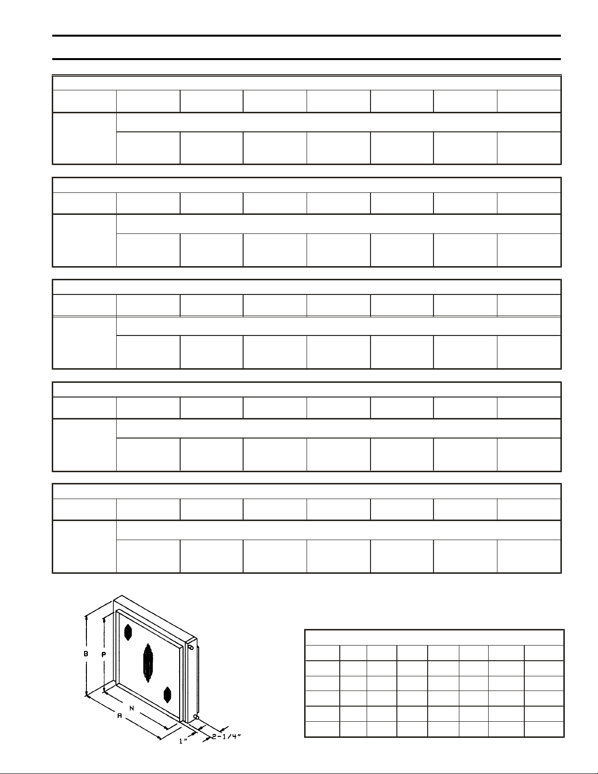
These are typical drawings for dimensional purposes only. They
are correct within limits suitable for normal installation
requirements and do not necessarily show actual construction.
HC DIMENSIONS (in.)
MODEL A B N P INLET OUTLET WT. - lbs.
HC-07 17-3/4 15-3/8 19 13-1/2 5/8 5/8 10
HC-09 21 18 19-1/8 16-1/8 5/8 5/8 14
HC-10 22-1/4 20 20-3/8 18-1/8 5/8 5/8 17
HC-12 27 23 25-1/8 21-1/8 5/8 3/4 23
HC-15 32-1/2 26-3/4 30-3/8 25-1/8 3/4 3/4 32
Page 18

COOLING COIL CAPACITIES
Acme Engineering & Manufacturing Corporation
Page 18
Based on 80 deg. F DB / 67 deg. WB Air in Temp.
Model CW-07 Based on 4 U.S. Gpm - Pressure drop - 2.8 ft wg
CFM 300 375 450 525 600 675 750
SP - in. wg 0.13 0.19 0.25 0.32 0.4 0.48 0.56
Water Temp.
DEG F Cooling Capacity - MBH - Total Heat / Sensible Heat
42 14.1 / 8.6 16.3 / 10.2 17.5 / 11.3 19.0 / 12.5 20.4 / 13.8 21.5 / 14.9 22.9 / 16.2
45 12.6 / 8.0 14.2 / 9.2 15.6 / 10.5 16.9 / 11.7 18.1 / 12.9 19.0 / 13.9 20.2 / 15.2
48 11.1 / 7.3 12.6 / 8.5 13.7 / 9.7 14.8 / 10.8 15.8 / 12.0 16.5 / 13.0 17.6 / 14.3
Model CW-09 Based on 4 U.S. gpm - Pressure drop - 2.2 ft. wg
CFM 400 500 600 700 800 900 1000
SP - in. wg 0.14 0.20 0.26 0.33 0.41 0.50 0.59
Water Temp.
DEG F Cooling Capacity - MBH - Total Heat / Sensible Heat
42 18.8 / 11.5 21.3 / 13.4 23.5 / 15.1 25.6 / 16.9 27.2 / 18.5 28.7 / 20.0 30.5 / 21.8
45 16.8 / 10.7 19.0 / 12.4 20.9 / 14.1 22.7 / 15.8 24.1 / 17.3 25.4 / 18.7 26.9 / 20.4
48 14.8 / 9.8 16.7 / 11.5 18.3 / 13.0 19.8 / 14.6 21.0 / 16.1 22.1 / 17.5 23.4 / 19.1
Model CW-10 Based on U.S. gpm - Pressure drop - 2.1 ft. wg
CFM 500 600 700 800 900 1000 1100
SP - in. wg 0.14 0.19 0.25 0.30 0.37 0.43 0.50
Water Temp.
DEG F Cooling Capacity - MBH - Total Heat / Sensible Heat
42 23.3 / 14.3 25.9 / 16.2 28.4 / 18.2 30.7 / 20.1 32.6 / 21.8 3402 / 23.4 35.7 / 24.9
45 20.8 / 13.2 23.1 / 15.1 25.3 / 16.9 27.3 / 18.7 28.9 / 20.3 30.3 / 21.8/ 31.6 / 22.9
48 18.3 / 12.2 20.3 / 13.9 22.1 / 15.6 23.8 / 17.4 25.2 / 18.9 26.4 / 20.4 27.5 / 21.8
Model CW-12 Based on U.S. gpm - Pressure drop - 2.5 ft. wg
CFM 700 850 1000 1150 1300 1450 1600
SP - in. wg 0.13 0.18 0.23 0.29 0.35 0.42 0.49
Water Temp.
DEG F Cooling Capacity - MBH - Total Heat / Sensible Heat
42 32.2 / 19.9 37.1 / 23.3 40.1 / 26.4 44.0 / 29.1 45.8 / 31.1 47.8 / 33.2 49.9 / 35.6
45 28.8 / 18.4 33.0 / 21.6 36.4 / 24.5 39.0 / 27.1 40.5 / 29.0 42.2 / 31.1 44.0 / 33.3
48 25.3 / 16.9 28.9 / 20.0 31.8 / 22.7 33.0 / 25.1 35.2 / 27.0 36.6 / 28.9 38.2 / 31.2
Model CW-15 Based on 8 U.S. gpm - Pressure drop - 5.0 ft. wg
CFM 1500 1600 1700 1800 1900 2000 2100
SP - in. wg 0.21 0.23 0.26 0.28 0.31 0.33 0.36
Water Temp.
DEG F Cooling Capacity - MBH - Total Heat / Sensible Heat
42 58.6 / 38.4 60.5 / 40.1 62.0 / 41.8 63.5 / 43.3 64.8 / 44.8 66.0 / 46.2 67.3 / 47.8
45 51.8 / 35.7 53.4 / 37.3 54.7 / 38.8 55.9 / 40.3 57.0 / 41.8 58.0 / 43.2 59.1 / 44.7
48 45.0 / 33.0 46.4 / 34.6 47.4 / 36.1 48.4 / 37.5 49.3 / 38.9 50.2 / 40.2 51.1 / 41.7
Other capacities are available upon request.
CW DIMENSIONS (in.)
MODEL A B N P INLET OUTLET DRAIN wt.-lbs.
CW-07 17-3/4 15-3/8 16 13-1/2 5/8 5/8 5/8 22
CW-09 21 18 19-1/8 16-1/8 7/8 7/8 5/8 29
CW-10 22-1/2 20 20-3/8 18-1/8 7/8 7/8 5/8 36
CW-12 27 23 25-1/8 21-1/8 7/8 7/8 5/8 42
CW-15 33-1/2 28 30-5/8 25-1/8 7/8 7/8 5/8 61
These are typical
drawings for
dimensional purposes
only. They are
correct within limits
suitable for normal
installation
requirements and do
not necessarily show
actual construction.
Page 19
TYPICAL SELECTION EXAMPLE
Page 19
Acme Engineering & Manufacturing Corporation
Heating Coil Capacity
Air Temperature Correction Factor Useful Formula
Air Temp. Water Temp. Deg. F
Deg F 140 160 180
80 0.86 0.89 0.91
70 1.00 1.00 1.00
60 1.14 1.11 1.09
50 1.29 1.22 1.18
Air Temp. Rise = Mbh x 1000
Cfm x 1.08
Water Temp. Drop = Mbh x 1000
Gpm x 500
Typical Selection Example
Requirement
An application requires 40 Mbh heating and 26 Mbh of cooling.
Hot water temperature is 160 deg F. Chilled water is 45 deg F.
Selection
An HC-09 will provide 42.03 Mbh @ 160 deg F water temp with an air flow of 800 CFM.
The matching Cooling Coil, CW-09, needs 900 CFM to deliver the 26 Mbh cooling load
which will determine the design CFM. The system SP, excluding the coils and filter
section, has been calculated as 0.4 in. Wg based on the 900 CFM.
Static Pressure Estimate Blower Selection
Component sp - in. Wg
System 0.40
CW-09 Cooling Coil 0.50
HC-09 Heating Coil 0.12
F209A Filter 0.04
Total sp 1.06
Select Model DM09 or DMS09 duct blower
to match HC-09 & CW-09 dimensions
Motor Selection
From DUCTMASTER Catalog page 5 for DM or page 11 for
DMS performance data, at 900 CFM & 1” SP requires .28 BHP
@ 1126 RPM Select a 1/3 BHP motor
Page 20
CENTRIFUGAL
www.acmefan.com e-mail: acmefan@acmefan.com Au gust 2000 Form C65E
VENTILATION FANS
DUCT FANS
PROPELLER AND
INLINE CENTRIFUGAL
CEILING, INLINE AND
CABINET FANS
CENTRIFUGAL &
PROPELLER ROOF
EXHAUST FANS
CENTRIFUGAL &
PROPELLER ROOF
SUPPLY FANS
CENTRIFUGAL AIR
HANDLING FANS
CENTRIFUGAL AND
PROPELLER UPBLAST
ROOF EXHAUSTERS
CENTRIFUGAL AND
PROPELLER
WALL FANS
CENTRIFUGAL
INDUSTRIAL
PROCESS FANS
MAKE-UP AIR SYSTEMS
CENTRIFUGAL
HEAVY DUTY
INDUSTRIAL FANS
EXHAUST &
SUPPLY VENTS
LIMITED WAR RANTY Acme En gi neering
and Man u fac turing Cor po ra tion war rants the
prod ucts man u fac tured by Acme to be free
from orig i nal de fects in work man ship and ma te rial for two years sub ject to the terms and
con di tions of its pub lished lim ited war ranty.
War ranties on pur chased prod ucts are sub ject to the ven dor’s war ranty. Re fer to cur rent
Form MS149 for com plete lim ited war ranty
terms and con di tions.
WARNING Acme prod ucts are de signed and
man u fac tured to pro vide re li able per for mance but they are not guar an teed to be
100% free of de fects. Even re li able prod ucts
ACME ENGINEERING &
MANUFACTURING CORP.
P.O. Box 978, Muskogee, Oklahoma 74402
Telephone: 918-682-7791 Fax: 918-682-0134
will ex pe ri ence oc ca sional fail ures and this
pos si bil ity should be rec og nized by the User.
If these prod ucts are used in a life sup port
ven ti la tion sys tem where fail ure could re sult in
loss or in jury, the User should pro vide ad e quate back-up ven ti la tion, sup ple men tary
nat u ral ven ti la tion or fail ure alarm sys tem, or
ac knowl edge will ing ness to ac cept the risk of
such loss or in jury.
WARNING DO NOT use in HAZ ARD OUS
EN VI RON MENTS where fan’s elec tri cal sys tem could pro vide ig ni tion to com bus ti ble or
flam ma ble ma te ri als un less unit is spe cif i cally
built for haz ard ous en vi ron ments.
Mem ber Air Move ment and Con trol As so ci a tion
CAU TION Guards must be in stalled when fan
is within reach of per son nel or within seven (7)
feet (2.134 m) of work ing level or when
deemed ad vis able for safety.
DIS CLAIMER The Com pany has made a dili gent ef fort to il lus trate and de scribe the prod ucts in this lit era ture ac cu rately; how ever, such
il lus tra tions and de scrip tions are for the sole
pur pose of iden ti fi ca tion, and do not ex press or
im ply a war ranty that the prod ucts are mer chant able, or fit for a par ticu lar pur pose, or that
the prod ucts will nec es sar ily con form to the il lus tra tions or de scrip tions or di men sion.
 Loading...