

Page 1
Page 2

TABLE OF CONTENTS
DESIGN FEATURES
Page No
Design Features ..................................2-3
Optional Accessories...........................3
Hub & Blade Combinations .................4
Typical Specifications..........................4
AVD Performance Diagrams ...............5-8
AVD Dimensions ................................. 9
AVD Fan Weight..................................10
Metric Conversion Table......................10
Typical Installation...............................11
Warranty.............................................. 12
The VANEMASTER
™
impeller consists of two assembled hub discs with cavities to house the blades at preset
.
Acme Axial Flow Fans
™
The VANEMASTER
fans are compact, rugged, and precisely
constructed for your airflow-pressure conditions with adjustable
pitch blades (at rest).
VANEMASTER
™
fans are suited for a large number of air
handling applications in commercial, industrial and process
ventilation.
Distinguishing features of the VANEMASTER
™
fans are space
savings, ease of installation and high reliability.
angles. The blades of the rotor can be factory set to any angle between 25° and 60°, dependent on size and
speed. The rotor is provided with a hub boss for mounting onto the motor shaft.
Aluminum Blades: Special Operating
Ranges
Normal Operating Temperature -4 to 104°F
•
(-20 to 40°C) for standard fans.
• Maximum Temperature Range of the fan is
-40 to 302°F (-40 to 150°C) with special
motors and/or reduced speeds.
Motors
Standard motors are NEMA frame, flange
mounted type.
BLADE
MOTOR/BLADE ASSEMBLY
Adjustment Of Blade Angles
The blade pitch may be manually adjusted to obtain different performances. The rotor must be aligned and
balanced before starting. Care must be taken to not exceed the motor output power.
AVD For Duct Installations
™
The VANEMASTER
1600mm) and 7 hub diameters from 6 to 23 inches (152 mm to 584 mm). Air volumes from 212 to 116,500 CFM
(0.01 m
3
/s to 54.98 m3/s). The fan consists of a cylindrical casing with connecting flanges at both ends.
fan line comprises 14 sizes with impeller diameters ranging from 10 to 63 inches (254mm to
The mounting for the rotor serves as a downstream guide vane arrangement ensuring extremely high fan
efficiency.
The motor is flange-mounted and is provided with extended leads through the fan casing to a terminal box for
electrical connection.
Variable Frequency Controls
™
When designing ventilation and air conditioning systems, the VANEMASTER
fans with frequency convertors are
an excellent alternative to centrifugal fans with inlet vane controls for systems requiring varying air quantity
requirements.
Acme Engineering & Manufacturing Corporation certifies that the
models shown herein are licensed to bear the AMCA seal. The ratings
shown are based on tests and procedures performed in accordance
with AMCA Publication 211 and AMCA Publication 311 and comply
with the requirements of the AMCA Certified Ratings Program.
The sound ratings shown are loudness values in fan sones at 5 feet
(1.524 m) in a spherical free field calculated per AMCA Standard 301.
Values are shown are for Installation Type A: Free Inlet spherical
sone levels.
Model AVD is Listed for (UL/C-UL 705)
File No. E39982.
Consult your Acme representative for
availability.
Acme Engineering and Manufacturing Corporation Page 2
Page 3
DESIGN FEATURES
Investment, operating costs, and space requirements are lower for VANEMASTER™fans used in combination
with frequency converters that make even small installations economical.
The simple construction of VANEMASTER
™
fans provides a stable structure which minimizes vibration. Normally
there is only one or more vibration modes in which the associated speed(s) must be avoided. This is easily
accomplished by programming the variable frequency control.
As may be seen in the table, frequency control permits speeds and capacities in excess of the standard motor
rating. Care must be taken to not exceed the available motor output power or the maximum rotor speed.
Contrary to fixed speed fans, the use of speed regulation improves sound as lower speeds result in lower sound
power levels.
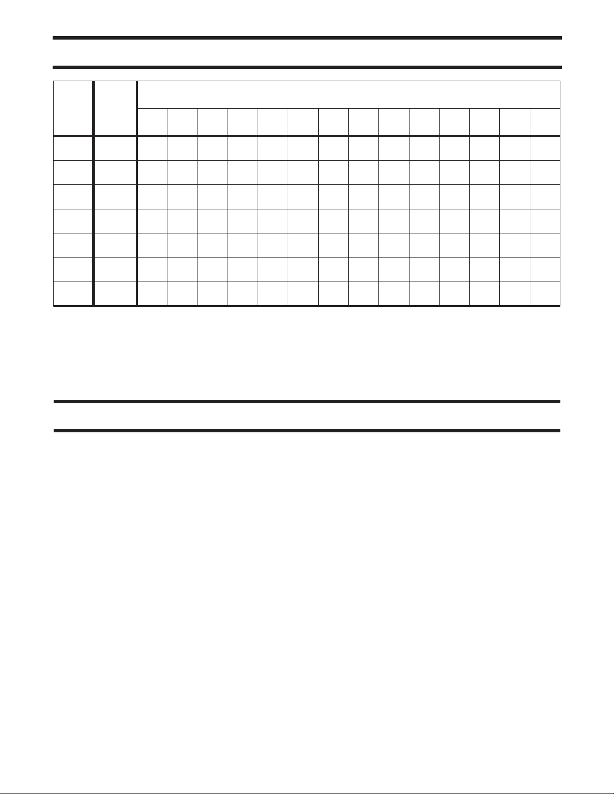
Max Speed (RPM) of VANEMASTER™ Rotors At 70 F (21 C)*
Hub
250 315 400 500 560 630 710 800 900 1000 1120 1250 1400 1600
5827 5080 4436 3943
160
230
280
330
380
403
578
4695 4112 3865 3676 3393 2993
4012 3755 3536 3334 3058 2571
3977 3686 3448 3215 2973 2665
3674 3388 3097 2859 2651 2324
NOMINAL WHEEL SIZE (mm)
2279 2125 1985 1833 1710
2128 1957 1804 1673 1553 1444
*Maximum allowable speeds may be adjusted for temperatures higher or lower than 70°F
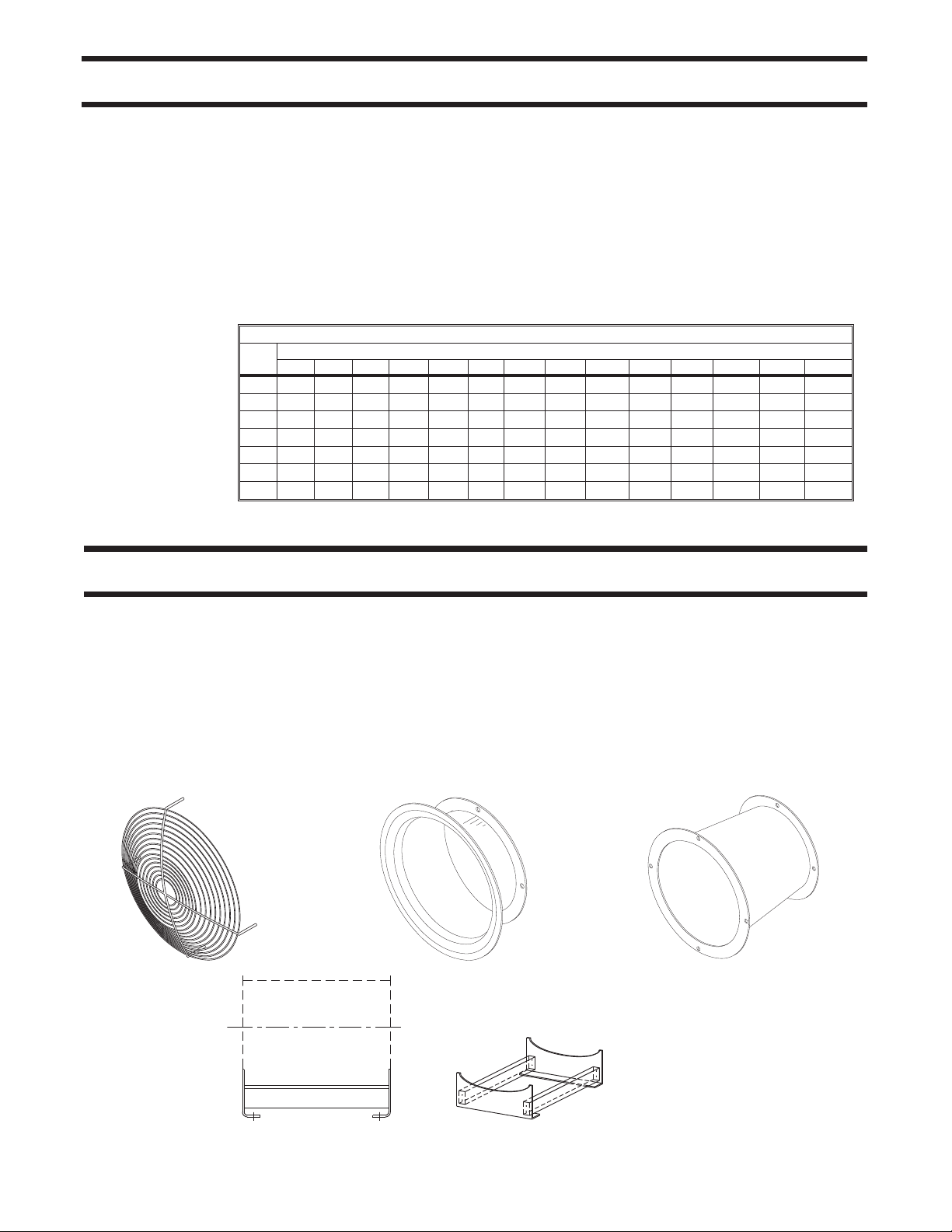
OPTIONAL ACCESSORIES
Mounting feet
Curb Cap(Sizes 400-1250)
Inlet/Guard
Inlet Bell
Outlet Guard
Discharger Hood
(Sizes 250-900)
Outlet Diffusers
(Sizes 800-1600)
Vibration Isolation mountings
Diffuser for outlet (short & long)
For sizing or details of these
accessories please review the
appropriate drawings.
Diffusers create lower discharge velocity
thus recovering some static pressure.
Diffuser can also be used on the inlet for
duct size differences.
Mounting Feet, Horizontal Air Flow.
Page 3 Acme Engineering and Manufacturing Corporation
Page 4
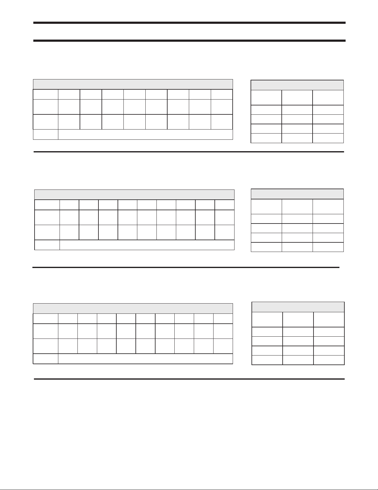
HUB AND BLADE COMBINATIONS
Hub
dia.
(mm)
160 4
230 6
280 8
330 10
380 12
403 6
578 10
AVD VANEMASTER™fans should be specified by giving both the fan diameter and the hub diameter. A typical
fan selection example would be AVD 1000/403. Additional data concerning motor RPM, voltage, Hz and
accessories are required to create the proper fan selection for each application.
Number
of
Blades
250 315 400 500 560 630 710 800 900 1000 1120 1250 1400 1600
••••
••••••
••••••
••••••
FAN DIAMETER (mm)
••••••
•••••
••••••
TYPICAL SPECIFICATIONS
Vane Axial fans shall be Direct Driven, Arrangement 4, with the motor located downstream from the impeller.
Impeller blades are to be made of a high strength, corrosion resistant, aluminum alloy. Blades are to be die cast
for maximum efficiency and low noise levels. The impeller hubs are to be die-formed of galvanized steel with
angle location marks to allow accurate blade setting at the factory or in the field.
The impeller shall be positively secured to the motor shaft. The impeller is to be statically and dynamically
balanced.
Fan housings shall be constructed of heavy gauge steel with integral prepunched flanges for leak-free
performance. High efficiency, straightening vanes of heavy gauge steel are to be installed to eliminate air swirl
and regain static pressure. The vanes are to be designed to support the motor and welded to the housings in a
manner designed to reduce air turbulence. Fans to be supplied with limited two year warranty.
Vane Axial fans shall be model AVD as manufactured by Acme Engineering & Manufacturing Corporation of
Muskogee, Oklahoma. Sizes and performance as shown on the plans.
Acme Engineering and Manufacturing Corporation Page 4
Page 5

AVD 560/330-10
1470 RPM
37° Blade Angle
AVD PERFORMANCE
CFM
Static
Pressure
Total
Pressure
Max HP
4958 4388 3901 3432 2925 2442
0.000 0.486 0.854 1.099 1.247 1.217
0.219 0.656 0.988 1.202 1.322 1.269
AVD 710/280-8
1470 RPM
43° Blade Angle
CFM
Static
Pressure
Total
Pressure
Max HP
10954 9854 8760 7672 6642 5485 4320 3345
0.000 0.398 0.722 0.945 1.068 1.143 1.232 1.439
0.160 0.521 0.819 1.019 1.124 1.181 1.256 1.453
Air Performance
.92
Air Performance
2.09
Sound Data
Static
Pressure
0.00 14.1 81
0.47 12.9 80
0.89 13.9 81
1.21 21 88
Spherical
Sones
Sound Data
Static
Pressure
0.00 20 87
0.31 20 87
0.58
0.86 26 92
Spherical
Sones
21 87
LwA
LwA
AVD 710/330-10
1470 RPM
45° Blade Angle
Air Performance
CFM
Static
Pressure
Total
Pressure
Max HP
Performance certified is for Installation Type B: Free inlet, ducted outlet.
Performance ratings do not include the effects of appurtenances (accessories).
The A-weighted sound power ratings shown have been calculated per AMCA Standard 301.
Values shown are for (Inlet LwA) sound power levels for: Installation Type B: free inlet, ducted outlet.
The sound ratings shown are loudness values in fan sones at 1.5 m (5 ft) in a spherical free field calculated per AMCA Standard 301.
Values shown are for Installation Type B: free inlet spherical sone levels.
11913 10738 9568 8388 7155
0.000 0.518 0.966 1.334 1.536
0.493 0.914 1.280 1.575 1.711
3.03
Static
Pressure
0.00 21 87
0.64 20 87
1.24 26 92
1.39 31 95
Sound Data
Spherical
Sones
LwA
Page 5 Acme Engineering and Manufacturing Corporation
Page 6
AVD PERFORMANCE
AVD 800/380-12
1470 RPM
39° Blade Angle
CFM
Static
Pressure
Total
Pressure
Max HP
13886 12535 11169 9804 8383 7019 5543 4130
0.000 0.620 1.169 1.589 1.827 2.012 2.122 2.260
0.426 0.966 1.443 1.800 1.980 2.120 2.189 2.297
AVD 900/380-12
1470 RPM
43° Blade Angle
CFM
Static
Pressure
Total
Pressure
Max HP
20368 18349 16355 14345 12373 10113 8273 6168 3426
0.000 0.647 1.205 1.645 1.911 2.111 2.214 2.391 2.774
0.541 1.085 1.552 1.911 2.109 2.243 2.302 2.440 2.789
Air Performance
3.62
Air Performance
5.78
Sound Data
Static
Pressure
0.00 27 91
0.80 26 91
1.40 37 98
1.70 44 101
Static
Pressure
0.10 34 95
0.70 33 95
1.30 46 101
1.90 62 106
Spherical
Sones
Sound Data
Spherical
Sones
LwA
LwA
AVD 1000/403-6
1470 RPM
39° Blade Angle
Air Performance
CFM
Static
Pressure
Total
Pressure
Max HP
Performance certified is for Installation Type B: Free inlet, ducted outlet.
Performance ratings do not include the effects of appurtenances (accessories).
The A-weighted sound power ratings shown have been calculated per AMCA Standard 301.
Values shown are for (Inlet LwA) sound power levels for: Installation Type B: free inlet, ducted outlet.
The sound ratings shown are loudness values in fan sones at 1.5 m (5 ft) in a spherical free field calculated per AMCA Standard 301.
Values shown are for Installation Type B: free inlet spherical sone levels.
27190 24566 21776 19088 16426 13396 10909 8188 3768
0.00 0.697 1.416 1.990 2.377 2.758 2.919 3.016 3.808
0.627 1.203 1.813 2.294 2.602 2.908 3.018 3.072 3.820
8.79
Static
Pressure
0.00 40 97
1.00 37 97
2.00 47 102
3.00 66 107
Sound Data
Spherical
Sones
LwA
Acme Engineering and Manufacturing Corporation Page 6
Page 7

AVD 1000/578-10
1470 RPM
29° Blade Angle
AVD PERFORMANCE DIAGRAMS
CFM
Static
Pressure
Total
Pressure
Max HP
17372 15659 13986 12212 10438 8732 6974 5213 2551 0
0.00 0.911 1.720 2.433 2.904 3.246 3.638 4.164 4.976 6.276
0.265 1.122 1.888 2.561 2.997 3.312 3.679 4.188 4.981 6.276
AVD 1000/380-12
1470 RPM
47° Blade Angle
CFM
Static
Pressure
Total
Pressure
Max HP
30227 27320 24351 21308 18232 15168 12153 9040 4623
0.00 0.71 1.34 1.85 2.20 2.41 2.43 2.65 2.99
0.79 1.35 1.84 2.24 2.49 2.60 2.56 2.72 3.00
Air Performance
8.67
Air Performance
10.72
Sound Data
Static
Pressure
0.00 48 99
1.50 49 102
3.00 62 106
4.00 63 105
Static
Pressure
0.00 41 99
0.63 42 99
1.27 52 102
1.90 68 107
Spherical
Sones
Sound Data
Spherical
Sones
LwA
LwA
AVD 1120/403-6
1470 RPM
42° Blade Angle
Air Performance
CFM
Static
Pressure
Total
Pressure
Max HP
Performance certified is for Installation Type B: Free inlet, ducted outlet.
Performance ratings do not include the effects of appurtenances (accessories).
The A-weighted sound power ratings shown have been calculated per AMCA Standard 301.
Values shown are for (Inlet LwA) sound power levels for: Installation Type B: free inlet, ducted outlet.
The sound ratings shown are loudness values in fan sones at 1.5 m (5 ft) in a spherical free field calculated per AMCA Standard 301.
Values shown are for Installation Type B: free inlet spherical sone levels.
39677 35905 32052 28135 24129 20172 16078 12016 5680
0.00 0.76 1.47 2.11 2.55 2.87 3.04 3.34 4.05
0.86 1.46 2.03 2.54 2.87 3.09 3.18 3.41 4.07
14.75
Static
Pressure
0.00 51 101
0.82 45 100
1.65 49 101
2.47 83 111
Sound Data
Spherical
Sones
LwA
Page 7 Acme Engineering and Manufacturing Corporation
Page 8

AVD PERFORMANCE DIAGRAMS
AVD 1120/578-10
1470 RPM
34° Blade Angle
CFM
Static
Pressure
Total
Pressure
Max HP
33430 30372 27183 23835 20388 16946 13544 10234 5046
0.00 1.22 2.33 3.23 3.82 4.21 4.50 4.82 5.76
0.61 1.72 2.73 3.54 4.05 4.36 4.60 4.87 5.77
AVD 1250/403-6
1470 RPM
46° Blade Angle
CFM
Static
Pressure
Total
Pressure
Max HP
55837 50530 45064 39456 33871 28266 22529 16786 8095
0.00 0.82 1.63 2.31 2.84 3.23 3.31 3.69 4.42
1.08 1.71 2.33 2.85 3.23 3.50 3.48 3.79 4.44
Air Performance
18.04
Air Performance
22.59
Sound Data
Static
Pressure
0.00 62 103
1.13 56 102
2.26 63 105
3.38 81 110
Static
Pressure
0.00 65 106
0.94 60 105
1.89 63 105
2.84 114 115
Spherical
Sones
Sound Data
Spherical
Sones
LwA
LwA
Performance certified is for Installation Type B: Free inlet, ducted outlet.
Performance ratings do not include the effects of appurtenances (accessories).
The A-weighted sound power ratings shown have been calculated per AMCA Standard 301.
Values shown are for (Inlet LwA) sound power levels for: Installation Type B: free inlet, ducted outlet.
The sound ratings shown are loudness values in fan sones at 1.5 m (5 ft) in a spherical free field calculated per AMCA Standard 301.
Values shown are for Installation Type B: free inlet spherical sone levels.
Acme Engineering and Manufacturing Corporation Page 8
Page 9

AVD DIMENSIONAL DATA
Hub Dia.
(mm)
A
B
C
160-
380
D
P
R
L 160-380
Hub Dia.
(mm)
A
B
C
230-
578
D
P
R
L 230-380
L 403
L 578
NEMA
Motor
Frame
All
Frame
Sizes
NEMA
Motor
Frame
All
Frame
Sizes
Size (Impeller Diameter)
AVD250 AVD315 AVD400 AVD500 AVD560 AVD630 AVD710
IN mm IN mm IN mm IN mm IN mm IN mm IN mm
12.20 310 15.16 385 18.90 480 23.23 590 25.59 650 28.35 720 31.50 800
11.02 280 13.98 355 17.72 450 22.05 560 24.41 620 27.17 690 30.31 770
.08 2 .08 2 .14 3 .14 3 .14 3 .14 3 .14 3
9.84 250 12.40 315 15.75 400 19.69 500 22.05 560 24.80 630 27.95 710
4.00 4 8.00 8 8.00 8 12.00 12 12.00 12 12.00 12 16.00 16
.38 10 .38 10 .50 12 .50 12 .50 12 .50 12 .50 12
14.17 360 15.75 400 20.47 520 22.05 560 24.41 620 24.41 620 28.74 730
Size (Impeller Diameter)
AVD800 AVD900 AVD1000 AVD1120 AVD1250 AVD1400 AVD1600
IN mm IN mm IN mm IN mm IN mm IN mm IN mm
35.04 890 39.37 1000 43.31 1100 48.03 1220 53.54 1360 59.45 1510 67.72 1720
33.86 860 38.19 970 42.13 1070 46.85 1190 51.97 1320 57.87 1470 66.14 1680
.14 3 .14 .75 .14 .75 .14 .75 .14 .75 .18 4 .18 4
31.50 800 35.43 900 39.37 1000 44.09 1120 49.21 1250 55.12 1400 62.99 1600
16.00 16 16.00 16 16.00 16 20.00 20 20.00 20 20.00 20 24.00 24
.50 12 .63 15 .63 15 .63 15 .63 15 .63 15 .75 19
29.53 750 33.86 860 35.43 900
25.59 650 29.53 750
33.46 850 29.53 750 25.59 650 29.53 750 33.46 850
33.46 850 29.53 750 29.53 750 29.53 750 33.46 850
35.43 900 33.46 850 33.46 850 33.46 850
29.53 750 25.59 650 29.53 750
33.46 850 29.53 750 29.53 750 29.53 750 33.46 850
33.46 850 35.43 900 33.46 850 33.46 850 33.46 850
35.43 900 37.40 950 37.40 950 37.40 950 35.43 900
37.40 950 37.40 950 37.40 950 44.09 1120
41.73 1060 44.09 1120 44.09 1120
44.09 1120 44.09 1120
Data shown on this page is for general information only and should not be used for exact installation dimensions.
Refer to a submittal drawing for detailed dimensions.
Accessory dimensions are available through your local Acme representatives.
Page 9 Acme Engineering and Manufacturing Corporation
Page 10

AVD FAN WEIGHTS
Hub
Dia.
(mm)
160-380 24 11 31 14 60 27 93 42 121 55 132 60 161 73
AVD250 AVD315 AVD400 AVD500 AVD560 AVD630 AVD700
lb. kg lb. kg lb. kg lb. kg lb. kg lb. kg lb. kg
Hub
Dia.
(mm)
160-380 181 82 216 98 295 134
403 258 117 340 154 368 167 406 184 445 202
578 337 153 423 192 441 200 593 269 725 329 807 366
AVD800 AVD900 AVD1000 AVD1120 AVD1250 AVD1400 AVD1600
lb. kg lb. kg lb. kg lb. kg lb. kg lb. kg lb. kg
Weight (Less Motors)
Weight (Less Motors)
Specific motor weights are available from your Acme representative.
CONVERSION TABLE
I-P Equivalents of Metric Units Metric Equivalents of I-P Units
3
3
= .062428 lbm/ft
= 62.428 lbm/ft
2
3
1 ft2(square foot) = .09290 m
3
1 lbm/ft
1 lbm/ft
3
3
1 ft-lb (foot pound) = 1.3558 N-m
1 Btu (British thermal unit) = 252 cal
1 CFM (Cu. ft/min) = .00047195 m
1 CFM = .02832 m
1 CFM = 1.6990 m
1 CFM = .47195 l/s
1 lb (pound) = 4.4482 N
1 lb = .45359 kp
1 ft-lb/lbm- R* = 5.3803 J/kg-K
-K (sq. mtr per sec. sq. Kelvin) = 5.9800 ft2/s2-R
1 ft
2/s2
- R** = .16723 m2/s2-K
1 Btu/lbm - R = 1.0000 cal/g- C
*(foot-pound per poundmass degree Rankine)
**(square-foot per second-square degree Rankine)
1" (inch) = 25.4 mm
1" = 2.54 cm
1 ft (foot) = .30480 m
1 mi (mile) = 1.6093 km
1 lbm (pound mass) = .45359 kg
1 hp (horsepower) = .7457 kW
1 hp = 745.70 W
1 hp = 1.0139 mhp
2
(Newton per m2)orPa (Pascal) = .0040264" wg
1" wg (inches water gauge) = 248.66 Pa or N/m
1" wg = 1.8651 mm Hg or torr
1 psi (pounds per sq. inch) = 6894.8 Pa or N/m
1" Hg (inch Mercury) = 3386.4 Pa or N/m
(inches wg at 68 F or 20 C)
2
= 1.732" wg
1"wg = 0.5774 oz./in
1 F (degree Fahrenheit) = 5/9 C
x9/5+32
C
For temperature in C =(t
1 lb-in. (pound inch) = .11298 N-m
1 lb-ft. (pound foot) = 1.3558 N-m
1 fpm (feet per minute) = .00508 m/s
1 mph (mile per hour) = 1.6093 km/hr
1 rpm (revolution per minute) = 60 rps
1 lbm/ft-s (pound/foot second) = 1488.2 cP
2
= 16.018 kg/m
= .016018 g/cm
3
/min
3
/hr
-32) x 5/9
F
Area
Density
Energy
Flow Rate
(Volume)
Force
Gas
Constant
Length
Mass
Power
Pressure
or
Stress
Temperature
Torque
Velocity
&
Speed
Viscosity
2
(square meter) = 10.764 ft
1 m
1 kg/m
1 g/cm
1 J (Joule) or N-m (Newton-meter) = .73756 ft-lb
1 kcal (kilo calorie) = 3.9683 Btu
3
1 m
/s (cubic meter per second) CMS = 2118.9 CFM
3
1 m
/min (cubic meter per minute) CMM = 35.315 CFM
3
1 m
/hr (cubic meter per hour) CMH = .58858 CFM
1 l/s (liter per second) = 2.1189 CFM
1 N (Newton) = .22481 lb
1 kp (kilopond) = 2.2046 lb
1 J/kg-K (Joule per kilogram Kelvin) = .18586 ft-lb/lbm- R
2/s2
1 m
1 cal/g- C (calorie per gram C) = 4186.8 J/kg-K
1 mm (millimeter) = .03937 inch
1 cm (centimeter) = .39370 inch
1 m (meter) = 3.2808 ft
1 km (kilometer) = .62137 mi
1 kg (kilogram) = 2.2046 lbm
1 W (Watt) = .00134 HP
1 kW (kilo-Watt) = 1.3410 hp
1 mhp (metric horsepower) = .98632 hp
1 N/m
1 mm Hg or torr (mm Mercury) = .53616" wg
1 kPa (kilo Pascal) = .1450 psi
1 atm (atmosphere) = 29.921" Hg
(mm Hg at 0°C or 68°F)
1 oz./in
For temperature intervals and rise, For temperature intervals and
rise,
1 C (degree Celsius) = 9/5 F
For temperature in F (Fahrenheit) = t
1 N-m (Newton meter) = 8.8507 lb-in.
1 N-m (Newton-meter) = .73756 lb-ft.
1 m/s = 196.5 fpm
1 km/hr (kilometer per hour) = .62137 mph
1 rps (revolution per second) = .016667 rpm
1 cP (Centipoise) = .00067197 lbm/ft-s
3
3
3
/s
2
2
2
2
Acme Engineering and Manufacturing Corporation Page 10
Page 11

TYPICAL INSTALLATION
INLET DUCT ELBOWS
Non-uniform flow into a fan inlet is the most common cause of deficient fan performance. An elbow located at, or
in close proximity to the fan inlet will not allow the air to enter the impeller uniformly. The result is less than
catalogued air performance. It is strongly advised that inlet elbows be installed a minimum of three (3) diameters
away from any axial or centrifugal fan inlet.
It is strongly advised that inlet elbows be installed a minimum of three (3) diameters away from any axial
or centrifugal fan inlet.
OUTLET DUCT ELBOWS
Values for pressure losses through elbows, which are published in handbooks and textbooks, are based upon a
uniform velocity profile approaching the elbow. Any non-uniformity in the velocity profile ahead of the elbow will
result in a pressure loss greater than the published value.
The velocity profile at the outlet of a fan is not uniform and an elbow located at or near the fan outlet will,
therefore, develop a pressure loss greater than its “handbook” value.
The amount of this increased loss will depend upon the location and orientation of the elbow relative to the fan
outlet. In some cases the effect of the elbow will be to further distort the outlet velocity profile of the fan. This will
increase the losses and may result in such uneven flow in the duct that branch takeoffs near the elbow will not
deliver their designed air flow.
Wherever possible a length of straight duct should be installed at the fan outlet to permit diffusion and
development of a uniform flow profile before an elbow is inserted in the duct. If an elbow must be located near the
fan outlet then it should have a minimum radius to duct diameter ratio of 1.5.
Reprinted from AMCA Publication 201-90, FANS AND SYSTEMS, with the express written permission from the
Air Movement and Control Association International, Inc., 30 West University Drive, Arlington Heights, IL
60004-1893.
Further information on axials and centrifugal fans is provided in the above mentioned publication.
Page 11 Acme Engineering and Manufacturing Corporation
Page 12

EXHAUSTERS
CEILING AND CABINET
EXHAUSTERS
IN-LINE CENTRIFUGAL
FANS
IN-LINE AXIAL FANSCENTRIFUGAL
PROPELLER
ROOF FANS
ROOF VENTS
WALL FANS
UTILITY BLOWERS
PLENUM FANS
SUPPLY AIR FANSPROPELLER
BACKWARD
INCLINED/AIRFOIL
CENTRIFUGAL FANS
LIMITED WARRANTY Acme Engineering and Man
ufacturing Corporation extends this limited warranty
to the original purchaser and warrants that products
described hereinshallbefreefromoriginaldefectsin
workmanship and materials for two years from date
of shipment(except for Acme’s exclusiveduplexsplit
pillow block bearings and shaft 5 years from ship
ment, belts one year from shipment, and polyethyl
ene tubing at 90 days from shipping), provided
same have been properly handled, stored, installed,
serviced, maintained and operated. Refer to Form
MS149 for complete limited warranty terms andcon
ditions. This form is available to anyone at
www.acmefan.com. The Company's warranty is in
lieu ofallotherwarranties, express or implied, arising
by law or otherwise, including without limitation the
implied warranties of merchantability and fitness for
a particular purpose, whichareherebyexpressly dis
claimed claimed and waived.
ACME ENGINEERING &
MANUFACTURING CORP.
P.O. Box 978, Muskogee, Oklahoma 74402
Telephone: 918-682-7791 Fax: 918-682-0134
www.acmefan.com e-mail: acmefan@acmefan.com
Acme products are designed and manufactured to
provide reliable performance but they are not guar
anteed to be 100% free of defects. Even reliable
products will experience occasional failures and this
possibility should be recognized by the Purchaser
and End User. If these products are used in a life
support ventilation system where failure could result
in loss or injury, the Purchaser and End User should
provide adequate back-up ventilation, supplemen
tary natural ventilation or failure alarm system, or ac
knowledge willingnessto accept the risk ofsuch loss
or injury.
-
WARNING DO NOT use in HAZARDOUS ENVI
RONMENTS where fan’s electrical system could
provide ignition to combustible or flammable materi
als unless unit is specifically built forhazardous envi
ronments. Comply with all local and national safety
codes including the National Electrical Code (NEC)
and National Fire Protection Act (NFPA). Guards
Member Air Movement and Control Association International, Inc.
must be installed when fan is within reach of person
-
nel or within eight (8) feet (2.5 m) of working level or
when deemed advisable for safety.
DISCLAIMER The Company has made adiligent ef
fort to illustrate and describe the products in thisliter
ature accurately; however, such illustrations and
descriptions areforthesolepurposeofidentification,
and do not express or imply a warranty that the prod
ucts are merchantable,orfitforaparticular purpose.
-
INDEMNITY Purchaser acknowledges various
warnings by the Company regarding the products
and its installation and use. If the Company incurs
any claims, lawsuits, settlements, or expenses (in
cluding attorney fees) for any loss, injury, death or
property damage including, but not limited to, claims
arising out of the Purchaser’s or any end user ’s in
stallation or use of the products, the Purchaser shall
indemnify and hold the Company harmless.
January 2012 Form C66D
-
-
-
-
-
-
 Loading...