

Page 1
Acme Engineering & Manufacturing Corp.
P.O. Box 978
Muskogee, Oklahoma 74402
Phone 918/682-7791 Fax 918/682-0134
www.acmefan.com acmefan@acmefan.com
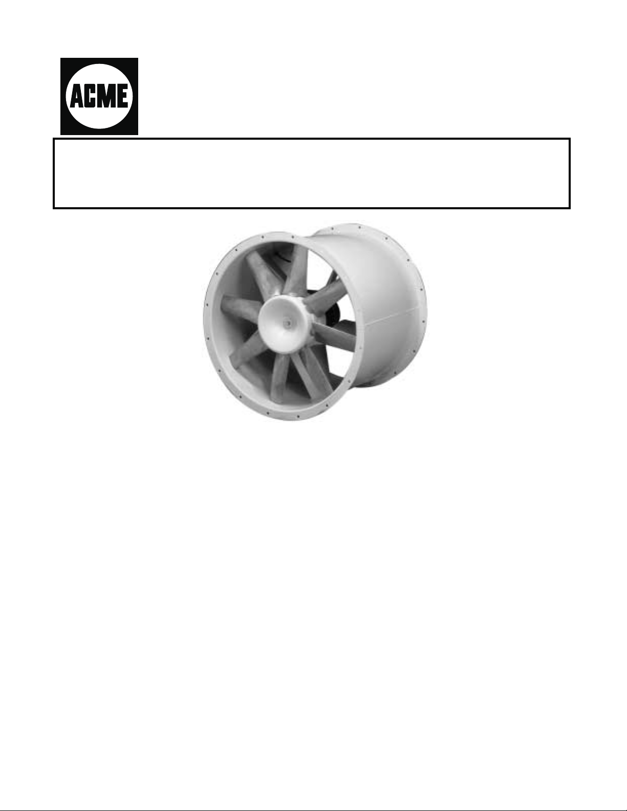
VANEMASTER FANS
SERIES AVD VANEAXIAL FAN
INSTALLATION/MAINTENANCE INSTRUCTIONS
Form 690016
I. Introduction
Your vaneaxial fan is a carefully engineered and
constructed piece of machinery which will give
long, satisfactory service provided correct
installation and proper maintenance practices
are observed. DO NOT DESTROY THIS
DOCUMENT AFTER INSTALLATION - RETAIN
WITH THE UNIT FOR MAINTENANCE.
Preventative maintenance including periodic
inspection, testing, cleaning, lubrication and
replacement of worn parts will forestall
equipment breakdowns and minimize equipment
shut-downs.
In addition to this manual, all fans are shipped
with the Air Movement and Control Association
(AMCA) Publication 410-90. “Recommended
Safety Practices for Users and Installers of
Industrial and Commercial Fans”. If you did not
receive this booklet, immediately contact the
factory to obtain a copy or contact AMCA directly.
The AMCA Safety Publication 410-90 should be
read before installing and operating the
equipment to insure safety of personnel and
equipment.
AMCA ARRANGEMENT 4 - DIRECT DRIVE
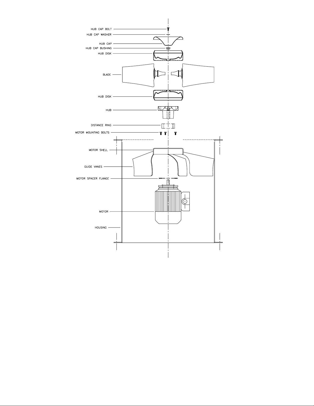
The basic AVD fan consists of a housing,
impeller, guide vanes, motor shell and a motor.
The AVD impeller consists of two assembled, die
formed, galvanized steel hub disks with cavities
to house the blades at preset angles. The
impeller blades are cast aluminum. The AVD
blades can be set at an angle between 25 and 60
degrees to allow precise performance selection.
The impellers are statically and dynamically
balanced at the blade angle required to obtain
the specified point of operation. The AVD fan
housing is accurately formed from plate steel with
integrally rolled inlet and outlet flanges. High
efficiency straightening vanes of heavy gauge
steel are installed downstream of the impeller to
eliminate swirl and regain static pressure. The
AVD straightening vanes are structurally
designed to support the weight of the motor and
impeller. TEFC, flange mounted motors are
provided as standard. The completely
assembled fan is given a running check test and
inspection before final shipment.
Page 2
II. AVD ACCESSORIES
A wide range of accessories and options are
available for the AVD fan:
1. Safety Guards are utilized to prevent
contact with rotating parts and prohibit
foreign objects from being drawn into the
fan. The wire guard is designed as a
heavy gauge wire screen which can be
supplied on the flanged fan housing or inlet
bell.
2. Inlet Bells are recommended whenever
the fan is intended for operation with an
open inlet. Inlet bells are formed from
heavy gauge steel to provide a smooth
entrance condition to the fan inlet and
minimize performance losses.
3. Housing Support Options fabricated of
heavy steel plate include: horizontal
mounting feet for floor mounting or ceiling
suspension.
4. Outlet Cones (Diffusers) are generally
used on the fan outlet to increase
pressure. These diffusers are sometimes
used on the inlet of the fan. The cones are
fabricated of heavy gauge steel and are
available in a short and long version.
2
Page 3

5. Roof Curb Mounting Base is designed for
vertical roof mounted units consisting of a
one piece, heavy gauge, reinforced steel
mounting platform for bolting to the fan
flange.
6. Discharge Hood for vertical mounted units
is designed for weather protection on either
the inlet or outlet side of the fan. The
discharge hood is constructed of heavy
gauge steel.
7. Other Available Options
· Access Doors in Housing
· Sound Attenuation
· Vibration Isolators
· Variable Frequency Drives
III.Installation and Start-Up
A. Receiving
Acme Eng. & Mfg. Corp.’s equipment is
thoroughly inspected and packaged at the
factory. When a carrier signs the Acme
Engineering & Manufacturing Corporation’s bill
of lading, the carrier accepts the responsibility for
any subsequent shortages or damage, evident
or concealed, and any claim must be made
against the carrier by the purchaser within 15
days after receipt. Evident shortage or damage
should be noted on the carrier’s delivery
document before signature of acceptance.
Inspection by the carrier of damage evident or
concealed must be requested. After inspection,
issue a purchase order for necessary parts or
arrange for return of the equipment to the Acme
factory for repair.
B. Handling
Acme Engineering & Manufacturing Corporation
fans are shipped completely assembled and
packaged. The units may be handled and
moved using good rigging techniques, being
careful to avoid concentrated stresses that will
distort any of the parts.
C. Safety Precautions
receive this booklet, immediately contact the
factory to obtain a copy or contact AMCA
directly. The AMCA Safety Publication 410-90
should be read before installing and operating
the equipment to promote safety of personnel
and equipment. This unit has rotating parts and
safety precautions should be exercised during
installation, operation and maintenance.
The maximum operating speed for which this fan
is designed must not be exceeded. These limits
are available through Acme Engineering &
Manufacturing Corporation’s Applications
Group.
The maximum operating temperatures are given
in “Installation” Section B.5, Item 9 below.
Do not use fans in hazardous environments
where fan’s electrical system could provide
ignition to combustible or flammable materials
unless built specifically for the environment.
D. Storage
Acme provides sufficient protection for shipping
the equipment to the jobsite. If the equipment is
not installed immediately, additional precautions
are necessary. For storage:
1. Equipment shall be kept in a dry area, free
from rigid and extreme changes in humidity
and protected from low temperature. The
unit should not be exposed to vibration.
2. Rotor should be blocked to prevent
windmilling.
3. The impeller should be rotated several
revolutions every 90 days to re-coat the
motor bearings with grease and to minimize
brinelling of the motor bearings.
4. Every 6 months, add high quality grease to
bearings to purge and replace old grease.
5. Upon removal from storage, bearings
should be supplied with an ample supply of
fresh grease to purge and replace the old
grease. High quality ball bearing grease
should be used per the motor
manufacturers recommendations.
In addition to this manual, all fans are shipped
with the Air Movement and Control Association
(AMCA) Publication 410-90, Recommended
Safety Practices of Users and Installers of
Industrial and Commercial Fans. If you did not
6. Acme does not recommend use of any
plastic to cover the fan equipment as this
can create condensation, rusting and
equipment damage.
3
Page 4

E. Installation
1. The basic fan consists of a housing,
impeller, guide vanes and a motor. The
motor is factory installed. The impeller
is supplied from the factory with the
blades set to the angle that
corresponds to the specified point of
operation (volume flow rate and
pressure) for the fan speed. The
impeller has been statically and
dynamically balanced with the blade
angle set to this position.
hole(s) are at the lowest point of the
motor.
5. The fan can be installed in a number of
ways, either horizontally or vertically:
· The fans can be supplied with
mounting feet (optional)
· Supported by ductwork if
sufficiently braced to support
the weight of the fan
· Ceiling suspended by specially
designed supports or hangers
The impeller design permits adjustment
of the blade angle over the full
performance range (25 to 60 degrees).
The quadrant at the base of the blade
covers an angular adjustment range
from 70 to 0 degrees in 5 degree
increments. An increase in the blade
angle will increase the motor load,
therefore, it must be determined that
the motor is capable of handling the
additional load. Changes in blade
angle (increase or decrease) may also
disrupt the balance of the impeller
causing increased vibration levels.
Please contact Acme’s Application
Engineering group before making any
adjustment of the blade angle.
2. Before installing the fan, check all
fasteners for tightness; particularly the
impeller and motor.
Turn the impeller by hand to make sure
it does not strike the fan housing. The
tip clearance of the impeller should be
close to the same along the entire
circumference of the housing. If this is
not the case, adjust the motor location
in the suspension arrangement. (See
the maintenance instructions for
dismantling and re-assembly of the fan
for motor servicing).
3. The fan is provided with an arrow label
showing the rotation and direction of air
flow through the fan. The fan should be
so installed that the required air flow
direction in the system is achieved.
4. If the motor is provided with
condensation drain holes, the fan
should be so installed that the drain
When the fan is finally secured in place,
make sure that the impeller rotates
freely in the fan housing. The tip
clearance between the impeller and the
fan housing should be close to the
same along the entire housing
circumference.
6. Ducts on the inlet and outlet side should
be so arranged that the airflow to and
away from the fan is straight and
unobstructed; i.e. there must be no
sharp bends immediately in front of the
inlet or outlet opening for at least three
(3) duct diameters.
Sharp ends or other obstructions at the
inlet or outlet of the fan can result in
reduced fan performance and/or
increased sound levels.
7. To prevent vibration from being
transmitted to the surroundings, the
fans can be furnished with optional
vibration isolation and flexible duct
connections (by others).
8. The natural frequency of the fan
mounting structure must differ by a
minimum of 20% from the fan speed.
9. Temperature Limitations
As standard, the fans are designed for a
gas temperature range of -20° C (-4° F)
to +40° C (+104° F). The temperature
range can be increased to -40° C
(-40° F) to +150° C (+302° F) with special
motors (lubrication), reduced speed
and/or increased tip clearance.
CAUTION! For applications at elevated
temperatures, the fan must operate
4
Page 5

after the process has been shut down
until the exhaust air or gas is cooled
sufficiently to protect fan components
from overheating.
10. Electrical Connections
IV. General Operation and Maintenance
A. CAUTION! Before proceeding with any
maintenance, make sure the motor
starter or disconnect switch to the fan is
locked in the “OFF” position.
Connections with the electrical supply
main should be made directly to the
outside terminal box located on the fan
housing.
When the power supply has been
connected, make sure that the direction of
rotation of the impeller is in accordance with
the arrow label on the outside of the fan.
F. Pre-operating Check List
After the equipment has been installed
correctly and a check has been made for
tightness of all hardware and mounting bolts,
the fan will be ready to operate after these
final safety checks to prevent injury to
personnel or damage to the equipment.
1. Check for correct supply voltage.
2. Remove all foreign matter from the
vicinity of the fan inlet(s)/outlet(s),
ductwork and interior of fan.
3. Check blade angle setting for desired
air performance (blade angle setting for
specified point of operation can be
found on fan nameplate).
5. Make sure that all safety guards are in
place.
6. Momentarily energize the fan to check
the direction of rotation.
7. Start the fan and check for the
following:
· Motor amperage in each
phase for balance and correct
motor load.
· Excessive vibration (not to
exceed a peak-to-peak velocity
of 7mm/sec (0.28 ins/sec).
· Unusual noise.
B. The fan housing and impeller require no
maintenance other than ordinary
cleaning. The motor needs to be kept
clean along with the fan housing and
impeller.
Excessive vibration occurring after the fan
has been in operation for some time will
usually be due to an accumulation of dust or
dirt on the impeller and should disappear
after cleaning. Dust buildups, in general,
occur uniformly with time not creating a
balance problem until the buildup reaches a
thickness where a portion of the buildup flies
off of the impeller initiating an unbalance
condition. If dust or dirt is not the problem, a
balancing specialist should be consulted to
analyze and rectify the problem.
C. To service the motor, the following
steps are required:
1. Disconnect the electrical cables
from the motor terminal box on the
fan housing.
2. Remove any ductwork adjacent to
the fan inlet and outlet.
3. Remove the impeller center bolt,
washer and hub cover.
4. Remove the impeller by means of a
pulley remover fastened to the two
threaded holes of the hub boss.
5. The motor will need to be supported
while the retaining bolts are being
loosened and removed from the
motor shell. The motor is now
completely accessible for service.
After servicing the motor:
1. New bolts, lock washers and nuts
should be utilized in re-assembling
the fan.
2. Re-mount the motor on the motor
mounting plate. Care must be taken
to locate the motor shaft in the exact
center of the housing. Motor
mounting bolts must be tight.
5
Page 6

3. Mount the impeller on the motor
shaft by aligning impeller on the
motor shaft. Utilize the impeller
center bolt, washer, hub cover and
drilled/threaded motor shaft to pull
impeller hub boss up against the
shoulder on the motor shaft.
Tighten the impeller center bolt
securely.
4. Ensure that the tip clearance of the
impeller to the fan housing is close
to the same along the entire
circumference of the housing. If this
is not the case, loosen and adjust
the motor location on the motor
mounting plate. Re-tighten the
motor mounting bolts when the
impeller is centered in the fan
housing.
5. Re-connect the electrical cables to
the motor terminal box. Check for
proper rotation.
6. Replace all inlet and/or outlet
ductwork.
7. Start fan and check vibration levels.
Vibration levels shall not exceed a
peak-to-peak velocity of 7mm/sec
(0.28 ins/sec).
D. The following steps are required to
change fan air performance by blade
angle adjustment.
1. Make certain that the required air
performance adjustment will not
overload the motor. You may need
to talk with Acme’s Application
Engineering group.
2. CAUTION! Before proceeding,
make sure the electrical service to
the fan is locked in the “OFF”
position. Disconnect the electrical
cables from the motor terminal box
on the fan housing.
3. Remove any ductwork adjacent to
the fan inlet.
4. Remove the impeller center bolt,
washer and hub cover.
5. Remove the impeller by means of a
pulley remover fastened to the two
threaded holes of the hub boss. The
weight of the impeller must be
properly supported to prevent blade
damage.
6. Loosen the bolts near the outer
diameter of the hub disc to a “snug”
tightness.
7. Adjust the blade angle by hand to
obtain the desired performance. It
is critical that all blades be set at
the same blade angle.
8. Tighten the bolts near the outer
diameter of the hub disc securely.
9. Mount the impeller by aligning
impeller hub boss on the motor
shaft. Utilize the impeller center
bolt, washer, hub cover and
drilled/threaded motor shaft to pull
impeller hub boss up against the
shoulder on the motor shaft.
Tighten the center bolt securely.
10.Replace the ductwork at the fan
inlet.
11.Return the electrical service to the
fan. Check for proper rotation.
12.Start fan and check vibration levels.
Vibration levels shall not exceed a
peak-to-peak velocity of 7 mm/sec
(0.28 ins/sec).
6
Page 7

NOTES
7
Page 8

TERMS AND CONDITIONS
DESIGN CHANGES The Company reserves
the right to make changes in design, improve
ments and additions in and to its products any
time without imposing any liability or obligations
to itself to apply or install the same in any prod
uct manufactured by it.
TITLE The title and right of possession of the
equipment sold herein shall remain with the
Company and such equipment shall remain
personal property until all payments herein (in
These instructions cover the usual installation, operation and maintenance methods for which the product(s) was designed. They do not purport to
cover all details or variations in the product(s) nor to provide for every possible contingency that might be met in connection with the installation, oper
ation and maintenance. For any departures from these instructions, or should particular problems arise which are not covered sufficiently for the pur
chaser’s purpose, the matter should be referred to the Company.
cluding deferred payments whether evidenced
by notes or otherwise) shall have been made in
full in cash and the Purchaser agrees to do all
acts necessary to perfect and maintain such
right and title in the Company.
-
SAFETY ACCESSORIES The Company manu
factures equipment designed to serve multiple
applications and offers a wide range of safety
equipment, including guards and other devices,
as may be required to meet customer specifica
-
tions. Without exception, the Company recom
mends that all orders include applicable safety
devices. Equipment ordered without applicable
safety devices is clearly the responsibility of the
Purchaser. Further, the Purchaser warrants
that he has determined and acquired any and
all safety devices required for equipment sold
by the Company. Weather covers and guards
for motor and V-belt drives, couplings, shafts
and bearings, along with inlet and outlet
screens, are optional accessories noted in the
price list.
-
-
-
-
WARNING The Company products are designed and manufactured to provide reliable performance but they are not guaranteed to be 100% free of de
fects. Even reliable products will experience occasional failures and this possibility should be recognized by the User. If these products are used ina
life support ventilation system where failure could result in loss or injury, the User should provide adequate back-up ventilation, supplementary natural
ventilation or failure alarm system, or acknowledge willingness to accept the risk of such loss or injury.
WARNING DO NOT use in HAZARDOUS ENVIRONMENTS where fan’s electrical system could provide ignition to combustible or flammable materials
unless unit is specifically built for hazardous environments.
CAUTION Guards must be installed when fan is within reach of personnel or within seven (7) feet (2.134 m) of working level or when deemed advisable
for safety.
DISCLAIMER The Company has made a diligent effort to illustrate and describe the products in this literature accurately; however, such illustrations and
descriptions are for the sole purpose of identification, and do not express or imply a warranty that the products are merchantable, or fit for a particular
purpose, or that the products will necessarily conform to the illustrations or descriptions or dimensions.
LIMITED WARRANTY
WARRANTY AND DISCLAIMER: The Com-
pany extends this limited warranty to the original buyer and warrants that products manufactured by the Company shall be free from original defects in workmanship and materials for
two years from date of shipment, unless otherwise noted (see specific product literature), provided same have been properly stored, installed, serviced, maintained and operated.
This warranty shall not apply to products which
have been altered or repaired without the Com
pany’s express authorization, or altered or re
paired in any way so as, in the Company’s
judgment, to affect its performance or reliability,
nor which have been improperly installed or
subjected to misuse, negligence, or accident, or
incorrectly used in combination with other sub
stances. The Buyer assumes all risks and liabil
ity for results of use of the products. Warranties
on purchased parts, such as but not limited to
bearings, sheaves, belts, couplings, electric
motors, pumps and controls are limited to the
terms of warranty extended by our supplier.
Polyethylene tubing and cooling pads are war
ranted to be free of defects in material and
workmanship for a period of 90 days from date
of shipment and a like warranty applies to the
cross fluted cellular type cooling cells for a pe
riod of two years from date of shipment pro
vided same have been properly handled,
stored, installed, serviced, maintained and op
erated. And further, not subjected to excessive
heat, corrosive agents or chemicals, or me
chanical abuse that may cause tearing, crush
ing or undue deterioration nor used on a sys
tem or in a manner other than that for which it
was designed as explained in the product litera
ture.
LIMITATION OF REMEDY AND DAMAGES:
All claims under this warranty must be made in
writing and delivered to P. O. Box 978, Musko
gee, Oklahoma, 74402, within 15 days after dis
covery of the defect and prior to the expiration
of the warranty period from the date of ship
ment by the Company of the product claimed
defective, and Buyer shall be barred from any
remedy if Buyer fails to make such claim within
such period.
Within 30 days after receipt of a timely claim,
the Company shall have the option either to inspect the product while in Buyer’s possession
or to request Buyer to return the product to the
Company at Buyer’s expense for inspection by
-
the Company. The Company shall replace, or
-
at its option repair, free of charge, any product
it determines to be defective, and it shall ship
the repaired or replacement product to Buyer
F.O.B. point of shipment; provided, however, if
circumstances are such as in the Company’s
-
judgment to prohibit repair or replacement to
-
remedy the warranted defects, the Buyer’s sole
and exclusive remedy shall be a refund to the
Buyer of any part of the invoice price, paid to
the Company, for the defective product or part.
The Company is not responsible for the cost of
removal of the defective product or part, dam
-
ages due to removal, or any expenses incurred
in shipping the product or part to or from the
Company’s plant, or the installation of the re
paired or replaced product or part.
-
-
Implied warranties, when applicable, shall com
mence upon the same date as the express war
-
ranty provided above, and shall, except for war
ranties of title, extend only for the duration of
-
the express warranty. Some states do not allow
-
limitations on how long an implied warranty
-
lasts, so the above limitation may not apply to
you. The only remedy provided to you under an
-
applicable implied warranty and the express
warranty shall be the remedy provided under
the express warranty, subject to the terms and
conditions contained therein. The Company
shall not be liable for incidental and consequen
-
tial losses and damages under the express
-
warranty, any applicable implied warranty, or
claims for negligence, except to the extent that
-
this limitation is found to be unenforceable un
der applicable state law. Some states do not allow the exclusion or limitation of incidental or
consequential damages, so the above limitation
or exclusion may not apply to you. This warranty gives you specific legal rights, and you
may also have other rights which vary from
state to state.
No employee, agent, dealer, or other person is
authorized to give any warranties on behalf of
the Company or to assume for the Company
any other liability in connection with any of its
products except in writing and signed by an offi
cer of the Company.
REPLACEMENT PARTS If replacement parts
are ordered, buyer warrants that the original
components in which these replacement parts
will be placed are in satisfactory working condi
tion, and when said replacement parts are in
stalled, the resultant installation will operate in
a safe manner, at speeds and temperatures for
which the original equipment was purchased.
-
TECHNICAL ADVICE AND RECOMMENDA
TIONS, DISCLAIMER: Notwithstanding any
-
past practice or dealings or any custom of the
trade, sales shall not include the furnishing of
technical advice or assistance or system de
sign. Any such assistance shall be at the Com
pany’s sole option and may be subject to addi
tional charge.
-
The Company assumes no obligation or liability
on account of any recommendations, opinions
or advice as to the choice, installation or use of
products. Any such recommendations, opinions
or advice are given and shall be accepted at
your own risk and shall not constitute any war
ranty or guarantee of such products or their
performance.
GENERAL In no event shall any claim for con
sequential damages be made by either party.
The Company will comply with all applicable
-
Federal, State, and local laws.
-
-
-
-
-
-
-
-
-
-
June 1998 Form 690016
 Loading...