

Page 1
AIRFOIL HIGH EFFICIENCY
CENTRIFUGAL FANS
8100
SERIES
ACME ENGINEERING & MANUFACTURING CORP.
MUSKOGEE, OKLAHOMA
Licensed to bear the AMCA seal for Sound and Air Performance
Page 2

8100 SERIES
DESIGN FEATURES
GENERAL
The 8100 Series Airfoil Centrifugal Fans utilize the latest
design techniques to produce a quiet, highly efficient air
mover. Aerodynamically designed airfoil blades and air
passages allow more air to be handled with less
horsepower and at a lower sound level. This fan has
been designed for applications where low operating cost
and quiet operation are prime considerations.
EFFICIENCY
Most important is sustained high efficiency over the
range of optimum selection. The ultimate measure of
fan performance is operating efficiency. High efficiency
means low operating costs throughout the life of the
equipment. Normal selection is slightly to the right of
peak efficiency, thereby assuring adequate pressure
reserve.
HORSEPOWER
The horsepower curve is self-limiting and reaches a
maximum in the normal selection range at a given
speed. Motors selected using this self-limiting power as
a basis will not overload as long as the speed is not
changed.
THESE ACROSS THE BOARD AIRFOIL ADVANTAGES…
Steeply Rising Pressure Curve. . .Ensures
n
minimum variation in volume with change in
system pressure and provides a pressure
reserve above the normal selection range.
Low Operating Cost. . .Maximum peak and
n
operating efficiencies, with minimum power
requirements.
Quieter Operation. . .Aerodynamically correct
n
airflow provided by airfoil blading permits quiet
operation, so important whenever air is moved.
Full Value. . .Superior design, workmanship,
n
application and service.
Wide Range of Application. . .Fans are available
n
to meet many commercial and industrial
requirements in both general purpose and heavy
duty construction.
ADD UP TO
Real Savings...low initial cost...minimum
n
operating expense...minimum maintenance
expense.
QUIET OPERATION
Precise orientation of wheel blades, combined with
careful aerodynamic design of wheel and casing,
decreases air turbulence and increases pressure
conversion efficiency. The result is a quieter operating
fan.
AIRFOIL BLADING
Provides full streamline airflow for greater operating
efficiency and perceptibly quieter performance.
8100 Series A.F.
Acme Engineering and Manufacturing Corporation,
Industrial Products Division, certifies that the 8100
Series fans shown herein are licensed to bear the
AMCA Seal. The ratings shown are based on tests
& procedures performed in accordance with AMCA
Publication 211 and AMCA Publication 311 and
comply with the requirements of the AMCA Certified
Ratings Program. For Sound Performance Data
refer to Sound Bulletin S92.
General Purpose...Classes I and II for medium pressures
U.L. 762 Listed
Consult your Acme representative for availability.
2
Page 3

TYPICAL CONSTRUCTION FEATURES
GENERAL PURPOSE FAN
8100 SERIES
BEARINGS
Self-aligning, grease lubricated,
anti-friction bearings are standard.
Minimum starting friction, simple
maintenance and long trouble-free life
expectancy make them ideal for fan
service. In general, ball bearings are
used for the higher speeds and roller
bearings for heavy loads and at
slower speed.
SPUN INLETS
Deep streamlined inlets reduce
incoming air turbulence and losses to
a minimum. Overlapping of the inlet
with the contoured wheel rims allows
air to move into the wheel without
obstruction.
REINFORCING BRACES
Angle bracing, which essentially forms a
beam section, eliminates the possibility
of casing pulsation and vibration. In
certain fan sizes, the bracing angles are
used to permit simple connection of
square or rectangular ducts directly to
the fan. This eliminates the usual duct
transition piece.
HOUSING DESIGN
The spiral shaped housing is
designed to receive the air leaving the
wheel and reduce its velocity with a
minimum of turbulence, thereby
efficiently converting the velocity
pressure to static pressure for
increased performance.
CUTOFF
The discharge cutoff is specially
shaped for maximum efficiency and
strength.
WHEEL CONSTRUCTION
Shock-free flow at the leading edge of
the blades, plus streamlined flow over
the blade surfaces, increases wheel
efficiency and quietness.
BASE
The base is fabricated from steel
angles for maximum support and
stiffness.
HEAVY BEARING SUPPORT
Heavy steel bearing supports
maintain accurate alignment, prevent
bearing distortion and offer a
minimum of resistance to airflow.
Wheels have die-formed airfoil blades
welded to backplate and rims to
provide a particularly rigid assembly.
All wheels are statically and
dynamically balanced to ensure
smooth operation.
SHAFTS
Shafts are fabricated from medium
carbon steel (larger fans utilize forged
shafts) and all are carefully turned,
ground and polished to size. All shafts
are correctly designed to give safe
deflection and operate well below the
first critical speeds.
3
Page 4

8100 SERIES
ARRANGEMENTS
SINGLE WIDTH (SWSI)
Arrangement 3. . .Single width fans are belt driven with
bearings supported by heavy steel members on each side of
the fan housing. This arrangement is generally used for ventilation, air conditioning and clean ambient air applications,
since the bearings are located in the airstream. Available in
sizes 8118 through 8154 for Classes I and II.
Arrangement 9. . .Similar in construction and application to
Arrangement 1, except the fan assembly has provision for
mounting the motor on the side of the bearing support ped
estal. Mounting the motor integral with the fan provides a
package which uses a minimum of floor area and is easily
movable. Available in all sizes, Classes I and II. Limited by
maximum motor frame.
ARR. 9
Arrangement 10. . .Similar to Arrangement 9, except that
the motor is mounted within the bearing support base. This
package fan uses a minimum of floor space, protects the
motor and is available with a weather cover or belt guard.
Furnished in Classes I and II, sizes 8118 through 8154.
-
ARR. 3
Arrangement 4. . .Direct driven has fan wheel overhung on
motor shaft and motor mounted on a pedestal. Available in
Classes I and II in sizes 8118 through 8137 only.
ARR. 10
DOUBLE WIDTH (DWDI)
Arrangement 3. . .Belt
driven with both bearings mounted in the inlets. Similar in
construction and application to Arrangement
3, SWSI. Double width
fans deliver a maximum
volume of air with a minimum amount of space
required. Available in
sizes 8118 through
8154, Classes I and II.
ARR. 4
General purpose, Arrangement 3, Double
Width, Double Inlet fan.
4
Page 5

8100 SERIES
FAN CONSTRUCTION
HOUSING
All SWSI and DWDI housings are fabricated from rigidly
braced steel and provided with streamlined spun inlets which
guide the air into the wheel with a minimum of interference.
Either fixed or rotatable discharge housings are available for
sizes 8118 through 8137, both single and double width.
Fixed discharge housings are standard for sizes 8140 and
larger, and are continuously welded.
Housings are fabricated using beaded or welded types of
construction depending on fan size or class.
WHEELS
The rotating elements of a fan are most important and must
be designed and fabricated to provide the highest practical
aerodynamic performance with smooth vibration-free
operation. This complete line of airfoil wheels features:
Shock-free airflow, minimizing turbulence and
n
sound.
Hubs designed to guide the air into the blades.
n
Wheels statically and dynamically balanced.
n
8100 DWDI AND SWSI AIRFOIL WHEELS
Welding of the double thickness airfoil blades to the wheel
back or center plate and rim(s) provides the necessary
strength and rigidity for all classes of construction.
Continuous welding of the trailing edge of the blades, not
only minimizes trailing eddies which contribute to the sound
output of the fan, but helps protect the hollow blading from
internal corrosion.
INTENDED SERVICE
In general, fans are built to suit the service for which they are
intended to perform. Variations in rotation, discharge, class
of construction, arrangements, bearing type and location are
but a few of the many different options that are available.
PROTECTIVE COATINGS
Standard finish for the 8100 Series fans consists of charcoal
baked enamel with U.V. inhibitors applied inside and out.
SPARK RESISTANT FANS
Application of fans on systems where hazardous, explosive
or flammable conditions exist requires careful attention on
the part of the designer, manufacturer and installer. The
8100 Series fans are available with spark resistant
construction as covered by the following table. Fans with
this construction are only available in arrangements 3, 4, 9
and 10. Aluminum wheels for Type A or B construction are
available for Class I and II.
Fans must be installed with all fan parts electrically
grounded.
8100 DWDI
n
Access Doors
n
Extended Lube Fittings
n
Flanged Inlet & Outlet
n
Heat Shield
n
Inlet & Outlet Screens
n
Inlet Boxes
n
Motor & V-Belt Drives
n
Outlet Dampers
8100 SWSI
n
Shaft & Bearing Guards
n
Shaft Seals
n
Spark Resistant Const.
n
Special Nameplates
n
Std. & Flanged Drains
n
Unitary Subbases
n
V-Belt Drive Guards
n
Weather Covers
OPTIONAL ACCESSORIES
Access
Doors
Vibration Equipment
Screens
Shaft Seal
Outlet Dampers
Drain
Drive Guards
5
Page 6
8100 SERIES
Table of Standard Classifications for Spark Resistant Construction.
Type A…
Type B…
Type C…
Notes: 1. Bearings shallnot be placed in the air orgas stream.
All partsof the fan in contact with theair or gas being handled
shall bemade of non-ferrous material. Steps must also be
taken toassure that the wheel, bearings, and shaftare
adequately attachedand/or restrained to prevent a lateral or
axial shiftin these components.
The fanshall have a non-ferrous wheel and non-ferrousring
about theopening through which the shaft passes. Ferrous
hubs, shaftsand hardware are allowed if construction issuch
that ashift of the wheel or shaft willnot permit two ferrous
parts ofthe fan to rub or strike. Steps must also be take n to
assure thatthe wheel, bearings, and shaft are adequately
attached and/orrestrained to prevent a lateral or axialshift in
these components.
The fanshall be so constructed that a shiftof the wheel or
shaft willnot permit two ferrous parts of thefan to rub or strike.
2. The usershall electrically ground all fan parts.
3. Explosion proof motors and static resistant belts should
be used.
Refer to AMCA Standard 99-0401-86 for more detailed information.
PHYSICAL DATA
AMCA Standard 99-2408-69 defines three performance
Classes, I through II.
Housings
Class I and II Fans
Sizes 8118 through 8137 SWSI or DWDI, tack welded,
beaded seams. Continuous welding optional.
Sizes 8140 and larger, SWSI or DWDI, continuous
welded seams.
Inlets
SWSI fans size 18-37, Class I and II are furnished with
circular Slip Joint Inlets as standard (Arr. 3, 4, 9 and 10).
The above applies to all fan Arrangements, except 3,
which for Class I and II, sizes 12-37 have a round flange
punched inlet as standard for both SW and DW. For
Arr. 3, 4, and 9, Class I and II, SW or DW, Sizes 40-54,
the standard inlet is a square flange open type
unpunched.
Outlets
Slip joint outlets are standard for Class I and II fans. If a
flanged type outlet damper is specified, a fan outlet
flange is also required.
Wheels
Class I, and II Fans
All SWSI or DWDI wheels are fabricated with die-formed
blades.
Blades
Wheel blades are welded to the rim, center or backplate.
Hubs
Hubs are fabricated from steel bar and plate or cast iron.
Shafts
Turned, ground and polished of SAE 1045 medium carbon
steel, designed to operate well below and away from the first
critical speeds.
Shaft Seals
Plate type sealant, backed by a steel retaining plate secured
to fan housing side around shaft opening.
Bearings
Class I and II Fans
All sizes and arrangements, SWSI or DWDI, are
supplied with pillow block type, ball or roller bearings as
standard.
With proper belt tension, Acme bearings are rated at a L-10
life of 40,000 hours. However, certain high speed and high
horsepower configurations may lead to reduced bearing life.
Outlet Dampers
Class I and II Fans
Dampers for all sizes and arrangements, SWSI or
DWDI, have independent frames and slip joint type duct
connection. They are multi-louver type, interconnected
and fabricated with bearings. A hand lever and locking
quadrant are furnished for manual operation and a stub
shaft for automatic control.
TYPICAL SPECIFICATIONS
FURNISH AND INSTALL WHERE SHOWN ON THE
PLANS, 8100 SERIES, CENTRIFUGAL A.F. FANS.
PERFORMANCE: Fans shall be licensed to bear the
AMCA Sound and Air Performance Seal with
performance ratings based on tests conducted in
accordance with AMCA Publication 211 and AMCA
Publication 311, and comply with the requirements of
the AMCA Certified Ratings Program. Fans shall
have a sharply rising pressure characteristic which
shall extend throughout the operating range and
continue to rise well beyond the efficiency peak to
insure quiet, stable operation under most conditions.
The horsepower characteristic shall be truly
non-overloading and shall peak within the normal
selection range.
DESIGN AND CONSTRUCTION: Housings shall be
of scroll centrifugal type, rigidly braced and reinforced
to help prevent vibration or pulsation. Wheel
diameters and outlet areas shall be in accordance
with the Standard Sizes adopted by AMCA for
non-overloading fans. Inlets shall be fully
streamlined.
WHEELS: Fan wheels shall be furnished with
die-formed airfoil blades for maximum efficiency and
quiet operation. Airfoil blades shall be continuously
welded to both backplate, rim, and along the back
edge of the blade to help prevent internal corrosion
due to moisture entry.
ACCESSORIES: Fans shall be furnished with
accessories as shown in the schedules.
6
Page 7
8100 SERIES
SELECTION AND APPLICATION
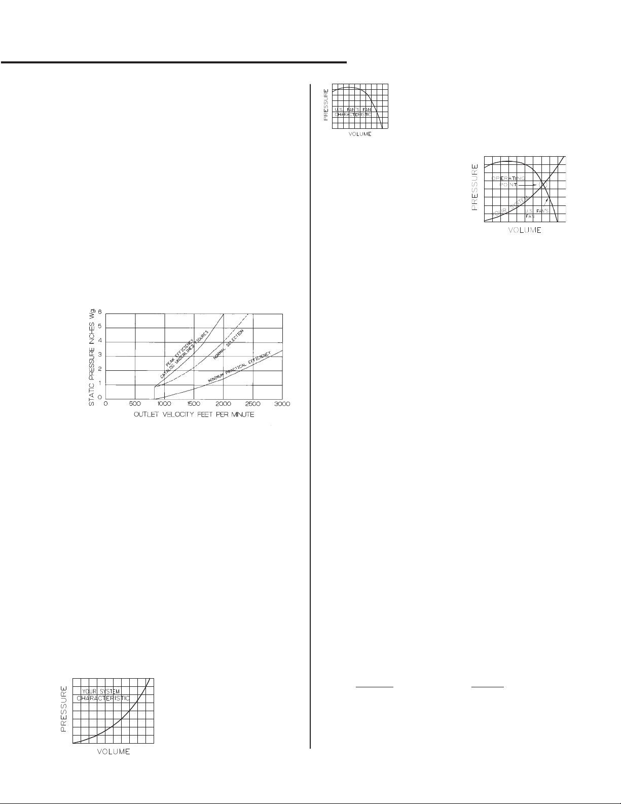
Efficient fan selection minimizes internal energy losses and
sound generation. Acoustical laboratory tests confirm that
low sound output occurs at high operating efficiency. The
figures with a
table are near peak efficiency. Fan selections near the peak
efficiency provide low sound output consistent with adequate
pressure reserve and self-limiting horsepower - another
advantage of carefully coordinated design.
Selection for relatively quiet operation...Selection at
higher efficiencies minimizes sound generation. For lower
sound output, together with other benefits of low power
consumption and operating cost throughout fan life, select
fans near Normal Selection Curve. When higher sound
levels are acceptable, together with smaller fans and higher
operating costs selection can be made at lower efficiencies.
Under these circumstances, sound attenuation may be
desirable.
SELECTION CONSIDERATIONS
Selection of the proper fan for a given application involves
not only the operating characteristics of the fan, but a careful
analysis of first cost versus operating cost, as well as
expected life, quietness of operation, location of equipment
and any other job limitations. Generally speaking,
permanent types of fan installations such as public buildings,
schools, or hospitals are expected to operate for many years,
during which time operating and maintenance costs can be
substantial factors. Quite often an analysis of first cost
versus operating costs for the life expectancy of the fan can
justify a higher initial investment using a larger fan with
higher efficiency. Industrial applications, on the other hand,
have indeterminate life expectancies and often permit
smaller fans to be selected at lower efficiencies. Each
installation should be thoroughly analyzed in its design stage
to insure that the ultimate objective is accomplished.
ACME’S FAN...YOUR SYSTEM
Fan selections are based on static pressure capability when
handling a given volume of air. The static pressure is
calculated for each system by following certain accepted
industry practices. This calculation of static pressure is at
best an inexact science with the error often compounded by
the addition of safety factors.
⎤ in each pressure column of the performance
Recommended Outlet Velocities
For Quiet Operation
If the system pressure
requirements for a given volume
of flow is known, the system
characteristic curve is a
parabola and can be predicted
mathematically. Such a system
curve is illustrated to the left.
A fan at a given RPM has a
characteristic pressure-volume curve
from wide open to blocked tight. Such a
fan curve is illustrated to the left.
If the curves are superimposed as
illustrated to the right, the intersection is the only point on the system
at which the fan can operate. If this
balance point does not satisfy the
system pressure and volume requirements, the system requirements or fan speed must be
adjusted until the required operating characteristics are obtained.
In the selection of a fan to meet calculated or specified pressure-volume conditions, it is important to apply, where possible, an adjustable fan drive with sufficient variation to
compensate for variances between actual and calculated operating conditions.
FAN STARTING REQUIREMENTS
A fan is an energy converter. Electrical energy rotates the
fan wheel through a driving motor and increases the static
pressure (potential energy) of the air handled by the fan in
order to overcome resistance to air flow offered by the duct
system. The wheel also increases the velocity pressure (kinetic energy) of the air which is the energy required to maintain the air in motion. The driving motor must be capable of
starting the fan from rest and accelerating it to operating
speed, with a minimum of disturbance to the electrical system. The information given below is useful in understanding
the motor problems that may arise.
To start and accelerate a fan to operating speed it is
necessary to:
1. Overcome bearing resistance. This resistance can
vary with the type of bearing used. It is low for
anti-friction types and relatively high for sleeve types.
2. Accelerate the inertia of the fan wheel and shaft.
This inertia is generally designated as the moment of
inertia or WR
accelerate it together with the inertia of the drive
sheaves or coupling. The moment of inertia for Class III
and IV fans will be greater than Class I and II fans,
because heavier wheels and shafts are used.
3. Provide energy to the fan wheel as it begins to
deliver air into the duct system. The horsepower
required varies with the cube of the fan speed ratio. It is
insignificant at low speeds, but increases rapidly as the
fan wheel comes up to operating speed.
At lower static pressures it is possible to select motors that
are too small. The fan operating brake horsepower could be
significantly less than the WR
fan to the point of operation. If the motor was sized to the
required operating
for the fan WR
possible to overheat the motor and overload the electrical
system. To assure the proper motor size you should refer to
the appropriate Application Data Booklet for this product.
2
. The motor must provide energy to
2
necessary to accelerate the
brake horsepower without consideration
2
, drive loss, and bearing loss, then it is very
7
Page 8
8100 SERIES
SELECTION AND APPLICATION
The minimum motor sizes indicated in the fan performance
data are based upon the use of standard, open dripproof or
enclosed, normal torque motors for across-the-line starting.
The use of other motors for reduced voltage starting, high
or low starting torques, designed with high inertia
capabilities, etc., should be checked to be sure they will
start and accelerate the fan without overheating the motor
or overloading the electrical circuit. The motors listed in the
performance data have been selected based on one start
per day and operation in an ambient temperature not
exceeding 104°F (40°C). More frequent starting or
operation in higher temperatures will probably require a
motor larger than the minimum sizes listed.
Motor recommendations for fan sizes 8137 through 8154
are based on the use of four pole, 1800 RPM motors.
Under certain operating conditions it may be possible to use
motors smaller than those listed in the performance tables.
The selection of smaller motors should be reviewed with the
motor supplier.
In general, smaller fans do not present a starting problem.
Hence, when a fractional horsepower is used, its starting
and accelerating characteristics should be carefully
checked.
A directly driven fan requires a larger motor to bring it up to
its operating speed than a belt driven unit. The required
inertia capability of the motor to start a fan and accelerate it,
varies as the square of the fan-motor speed ratio. Belt
driven arrangements are advantageous for the motor since
a relatively low motor inertia capability is required due to the
effect of the square of the fan-motor speed ratio. However,
a fan directly connected to a motor does not have this
speed difference and the mechanical advantage of the drive
ratio is nonexistent. The driving motor must, of necessity,
be larger than that indicated in the performance tables and
should be reviewed with the motor supplier.
Whenever outlet dampers are used, the starting load and
motor heating are reduced, if such devices are kept closed
until after the fan has accelerated to operating speed.
CORRECTION OF FAN PERFORMANCE FOR OTHER
THAN STANDARD AIR CONDITIONS
Air volumes to be handled by the fan must be calculated to
satisfy the application. A fan operating on a given system
at a given speed is a constant volume machine. The
density of air entering the fan (affected by temperature
and/or altitude) can vary, but the air volume delivered will
remain unchanged. The system resistance, the fan
pressure capability and brake horsepower will vary directly
with the air density.
In general practice the design system resistance is
calculated in the usual manner using standard air density
and the fan pressure requirements are determined for
“standard” conditions. This is sometimes known as the
equivalent pressure (SP
in the normal manner using the equivalent pressure (SP
). Select the fan from the catalog
E
),
E
noting the fan RPM and BHP. As indicated by fan law #2,
the design air volume and selected fan speed will remain
unchanged, but the fan pressure and horsepower will vary
with the air density. The system resistance will also vary
with the air density.
The design of many systems involves the calculation and
specification of air quantities by weight as in product drying
or combustion. Before a fan can be selected, the air
quantity must be converted to an air volume based upon
actual air density entering the fan inlet. The system
resistance equivalent static pressure (SP
) must be
E
determined using the air volume. The fan selection is now
made from the catalog using the calculated air volume and
the equivalent static pressure (SP
). Fan brake
E
horsepower corrections are made for air density variations
as indicated under Fan Law #2C.
For ease in calculations the table to follow contains air
density ratios for temperatures from -20°Fto800°F (-29°C
to 427°C) and barometric pressures from 29.92" to 20.58"
Hg (760 mm to 536 mm Hg).
FAN LAWS
Two basic fan laws relate performance variables for
any fan of a given design (such as the Series 8100).
An understanding of these relationships is necessary
to select fans when they are handling air or gas which
is different than standard or when fan performance
adjustments must be made on existing systems.
Both of these laws apply to a given unchanged
duct system.
FAN LAW #1
SPEED VARIABLE - CONSTANT AIR DENSITY
A. Volume (CFM)...Varies directly as the ratio of the
speeds.
⎛
⎞
RPM
CFM CFM X
=
21
⎜
⎝
RPM
2
⎟
⎠
1
B. Pressure (SP or TP)...Varies directly as the
square of the speed ratio.
Pressure Pressure X
=
21
⎛
⎜
⎝
RPM
RPM
2
⎞
2
⎟
⎠
1
C. Power...Varies directly as the cube of the speed
ratio.
BHP BHP X
=
21
⎛
⎜
⎝
RPM
RPM
3
⎞
2
⎟
⎠
1
FAN LAW #2
AIR DENSITY VARIABLE - CONSTANT SPEED
A. Volume (CFM)...Remains unchanged
B. Pressure (SP or TP)...Varies directly as the ratio
of the air densities.
Pressure Pressure X
=
21
⎛
Air Density
⎜
⎝
Air Density
⎞
2
⎟
⎠
1
C. Power...Varies directly as the ratio of the air
densities.
BHP BHP X
=
21
⎛
Air Density
⎜
⎝
Air Density
⎞
2
⎟
⎠
1
8
Page 9
8100 SERIES
SET SCREW TIGHTENING SCHEDULE
1. Before initial operation of thefan, tighten set screws
according to the procedure outlined below.
2. After 500 operating hours orthree months, whichever
comes first, tighten set screws to the full recommended
torque.
3. At least once a year,tighten set screws to the full
recommended torque.
PROCEDURE FOR TIGHTENING SET SCREWS IN
BEARINGS AND HUBS
One Set Screw Application
Using a torque wrench, tighten the set screw to the torque
recommended in Table 1.
Two Set Screw Application
1. Using a torque wrench, tightenone set screw to half of
the torque recommended in Table 1.
2. Tighten the second set screwto the full recommended
torque.
3. Tighten the first set screwto the full recommended
torque.
VARIABLE FREQUENCY DRIVES AND MOTORS
There are occasions when a Variable Frequency Drive (VFD)
will cause poor motor performance and possible damage. To
avoid these problems, the Company recommends the
following:
1. Select compatible motor and VFDinverter; if possible,
the motor and the innverter should be from the same
manufacturer or at least the inverter selected should be
recommended by the motor manufacturer.
2. A motor shaft grounding systemshould be used to
prevent motor bearing damage from eddy currents.
NOTE: The Company will not honor motor warranty claims if
the customer fails to follow these recommendations.
Table 1. Recommended Tightening Torque
for Set Screws
Set Screw Diameter Torque (in-lbs)
#10 35
1/4 80
5/16 126
3/8 240
7/16 384
1/2 744
9/16 1080
5/8 1500
3/4 2580
7/8 3600
1 5400
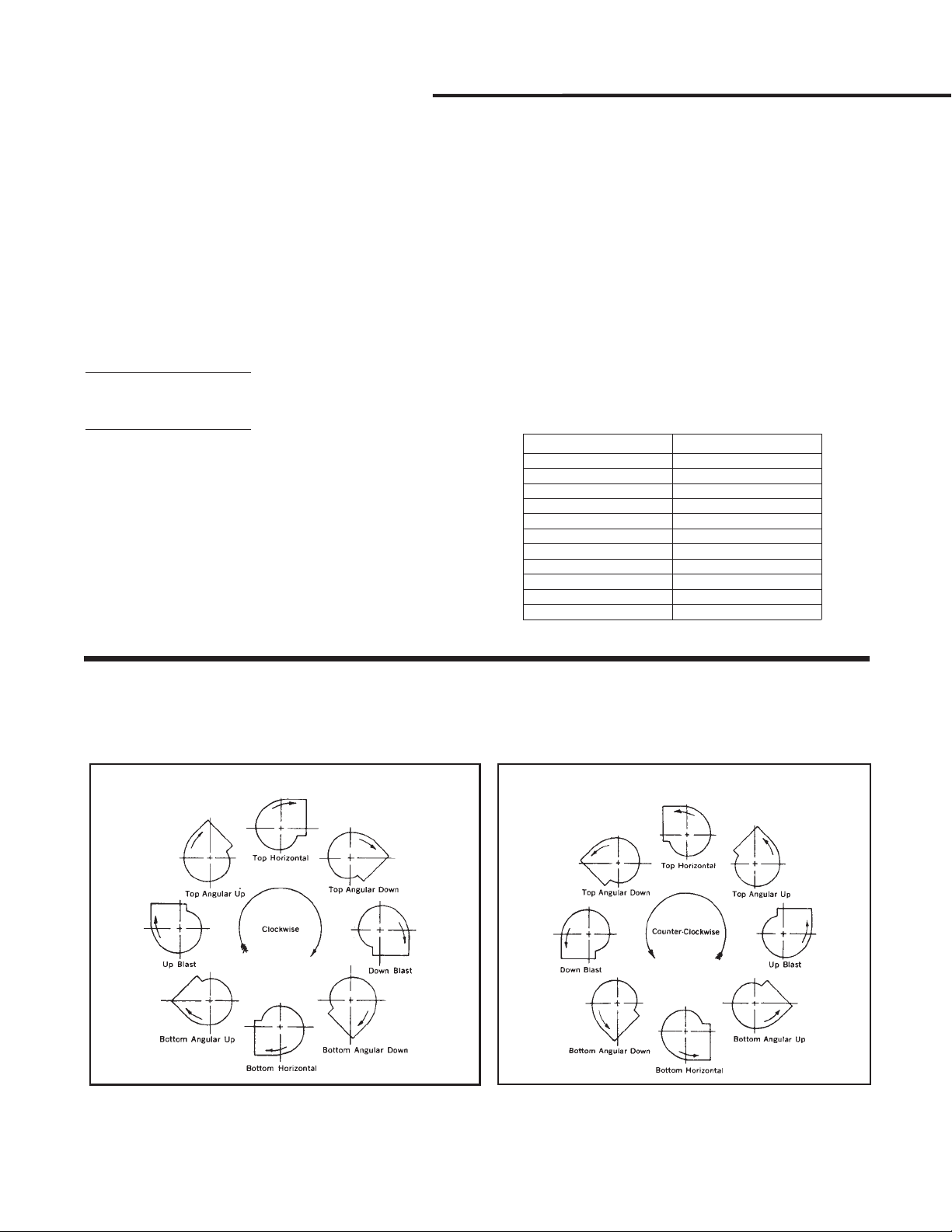
DESIGNATION FOR DIRECTION OF ROTATION AND DISCHARGE
Direction of Rotation is determined from the drive side for
either single or double width, or single or double inlet fans.
(The driving side of a single inlet fan is considered to be the
side opposite the inlet, regardless of the actual location of the
Reprinted from AMCA Publication 99-86 Standards Handbook, with the express written permission from the Air Movement
and Control Association International, Inc., 30 West University Drive, Arlington Heights, Illinois 60004-1893, U.S.A.
drive.) For fan inverted for ceiling suspension, the Direction
of Rotation and Discharge is determined when the fan is
resting on the floor.
9
Page 10
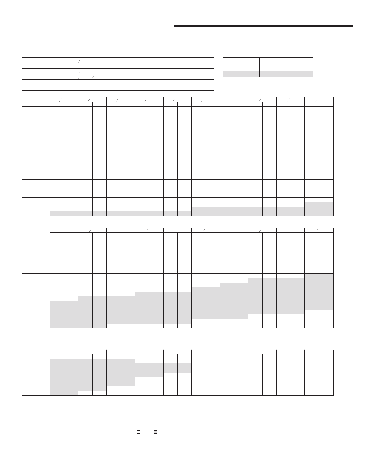
8100 SERIES
SINGLE WIDTH
SIZE 8118
"SP
4
1
18
4
3
20
16
1
19
16
Wheel Diameter
Wheel Circumference 4.78 feet 1.457 m
Inlet Diameter/Area
Outlet Size/Area
Tip Speed 4.78 x RPM ft./minute 1.457 x RPM m/minute
Maximum BHP .43 x (RPM 1000)
VOL
OUT
CFM
VEL
1144 600
1335 700 598 0.09 659 0.12 715 0.15 768 0.18
1526 800 649 0.11 704 0.14 758 0.18 807 0.22 852 0.25 900 0.29
1716 900 701 0.13 754 0.17 802 0.21 850 0.25 894 0.29 935 0.33 976 0.38 1057 0.46
1907 1000 755 0.16 805 0.21 851 0.25 894 0.29 937 0.34 977 0.38 1015 0.43 1089 0.52 1163 0.61
2098 1100 810 0.20 858 0.24 902 0.29 942 0.34 981 0.39 1020 0.44 1058 0.48 1127 0.59 1195 0.69 1262 0.79
2288 1200 865 0.23 911 0.29 953 0.34 993 0.39 1029 0.44 1065 0.49 1101 0.55 1170 0.66 1233 0.77 1294 0.88
2479 1300 922 0.28 965 0.33 1006 0.39 1044 0.45 1080 0.50 1114 0.56 1146 0.62 1213 0.73 1275 0.85 1333 0.97
2670 1400 979 0.33 1021 0.39 1060 0.45 1097 0.51 1131 0.57 1164 0.63 1196 0.69 1257 0.81 1318 0.94 1375 1.07
2861 1500 1036 0.39 1077 0.45 1114 0.51 1150 0.58 1183 0.65 1215 0.71 1246 0.77 1304 0.90 1362 1.04 1418 1.17
3051 1600 1095 0.45 1133 0.52 1169 0.58 1204 0.65 1236 0.72 1268 0.79 1297 0.86 1354 1.00 1407 1.14 1462 1.28
3242 1700 1154 0.52 1190 0.59 1225 0.66 1258 0.74 1290 0.81 1320 0.89 1349 0.96 1405 1.10 1456 1.25 1506 1.40
3433 1800 1213 0.60 1248 0.68 1281 0.75 1313 0.83 1344 0.90 1374 0.98 1402 1.06 1456 1.22 1507 1.37 1555 1.53
3623 1900 1273 0.69 1306 0.77 1338 0.85 1369 0.93 1399 1.01 1428 1.09 1455 1.17 1508 1.34 1558 1.50 1605 1.66
3814 2000 1333 0.78 1364 0.87 1395 0.95 1425 1.04 1454 1.12 1482 1.21 1509 1.29 1561 1.47 1609 1.64 1656 1.81
4195 2200 1454 1.00 1483 1.10 1511 1.19 1539 1.28 1566 1.37 1593 1.47 1618 1.56 1667 1.75 1714 1.94 1759 2.14
4577 2400 1576 1.26 1603 1.37 1629 1.47 1655 1.57 1680 1.67 1705 1.77 1729 1.87 1776 2.07 1821 2.28 1864 2.49
4958 2600 1698 1.57 1723 1.68 1748 1.79 1771 1.90 1796 2.01 1819 2.12 1842 2.23 1887 2.44 1930 2.67 1971 2.89
5340 2800 1822 1.92 1845 2.04 1868 2.16 1890 2.28 1912 2.40 1935 2.52 1956 2.63 1999 2.86 2040 3.10 2079 3.34
5721 3000 1945 2.32 1967 2.45 1989 2.58 2010 2.71 2030 2.84 2051 2.97 2072 3.09 2112 3.34 2151 3.59 2189 3.84
6102 3200 2069 2.78 2090 2.92 2110 3.05 2130 3.19 2150 3.33 2169 3.47 2188 3.60 2227 3.87 2264 4.13 2301 4.40
6484 3400 2193 3.30 2213 3.44 2232 3.59 2251 3.73 2270 3.88 2288 4.03 2306 4.18 2343 4.46 2379 4.74 2413 5.02
6865 3600 2318 3.88 2336 4.03 2354 4.18 2372 4.34 2390 4.49 2408 4.65 2425 4.80 2459 5.11 2494 5.40 2527 5.70
7247 3800 2442 4.53 2460 4.69 2477 4.85 2494 5.01 2511 5.17 2528 5.33 2545 5.50 2577 5.83 2610 6.14 2642 6.45
1
RPM BHP RPM BHP RPM BHP RPM BHP RPM BHP RPM BHP RPM BHP RPM BHP RPM BHP RPM BHP
•551 •0.07 •617 •0.10 •679 •0.12 •736 •0.15
SINGLE INLET
inches 464 mm
inches dia./2.18 sq. ft. 513 mm/.2025 m
1
x
inches I.D./1.90 sq. ft. 484 x 362 mm/.1765 m
14
4
3
BHP .3207 x (RPM 1000)3kW
3
8
"SP
1
"SP
2
5
"SP
8
3
4
•820 •0.21 •868 •0.25
"SP
2
2
7
"SP
8
MAXIMUM CLASS OPERATING RPM
FAN TEMPERATURE
SIZE 8118 -20° to 150°F -29° to66°C
CLASS I 2393
CLASS II 3122
"SP
1
1
"SP
1
4
•944 •0.33 •1028 •0.41
1
"SP
1
2
•1131 •0.54
3
1
•1230 •0.71
"SP
4
1
"SP
VOL
OUT
CFM
VEL
2479 1300 1389 1.09 1503 1.33
2670 1400 1429 1.20 1535 1.46 1638 1.71
2861 1500 1471 1.31 1570 1.59 1670 1.86 1765 2.14
3051 1600 1514 1.42 1612 1.72 1702 2.02 1797 2.31 1886 2.61
3242 1700 1558 1.55 1654 1.86 1743 2.17 1829 2.49 1917 2.80 2001 3.11
3433 1800 1602 1.69 1697 2.01 1785 2.33 1867 2.67 1949 3.01 2032 3.33 2111 3.66 2186 4.00
3623 1900 1650 1.83 1741 2.16 1828 2.51 1909 2.86 1986 3.21 2064 3.56 2142 3.91 2217 4.26 2289 4.61
3814 2000 1700 1.98 1785 2.33 1871 2.69 1951 3.05 2027 3.42 2099 3.80 2174 4.16 2249 4.53 2320 4.89 2388 5.26
4195 2200 1801 2.32 1882 2.70 1959 3.09 2038 3.47 2112 3.87 2183 4.27 2250 4.68 2315 5.10 2384 5.50 2452 5.90
4577 2400 1905 2.70 1983 3.11 2056 3.52 2126 3.95 2199 4.37 2268 4.79 2335 5.23 2398 5.67 2459 6.12 2518 6.57
4958 2600 2010 3.12 2086 3.57 2156 4.01 2224 4.46 2288 4.92 2355 5.37 2421 5.83 2483 6.29 2543 6.77 2602 7.24
5340 2800 2117 3.58 2190 4.07 2259 4.55 2324 5.03 2387 5.51 2446 6.00 2508 6.49 2570 6.98 2629 7.48 2687 7.98
5721 3000 2226 4.10 2296 4.62 2363 5.15 2427 5.65 2487 6.16 2546 6.67 2602 7.20 2658 7.72 2716 8.25 2773 8.77
6102 3200 2336 4.67 2404 5.22 2469 5.78 2531 6.34 2590 6.87 2647 7.42 2701 7.96 2754 8.52 2806 9.08 2861 9.63
6484 3400 2448 5.30 2513 5.88 2576 6.46 2636 7.06 2694 7.66 2749 8.22 2802 8.80 2854 9.38 2905 9.96 2954 10.56
6865 3600 2560 6.00 2623 6.60 2684 7.22 2742 7.84 2799 8.48 2853 9.10 2905 9.70 2956 10.31 3005 10.92 3053 11.54
7247 3800 2674 6.77 2735 7.40 2794 8.04 2850 8.69 2905 9.35 2958 10.02 3009 10.68 3058 11.31 3106 11.95
7628 4000 2788 7.61 2847 8.27 2904 8.94 2959 9.62 3012 10.30 3064 11.00 3114 11.70
8009 4200 2903 8.52 2961 9.21 3016 9.91 3069 10.61 3121 11.33
8391 4400 3019 9.51 3075 10.23
VOL
OUT
CFM
VEL
4195 2200 2517 6.30 •2642 •7.11 •2759 •7.93
4577 2400 2581 7.01 2705 7.88 2822 8.76 •2932 •9.65 •3040 •10.58
4958 2600 2658 7.73 2769 8.70 2885 9.64 2995 10.58 3100 11.54
5340 2800 2742 8.49 2849 9.52 2949 10.57 3058 11.58
5721 3000 2828 9.31 2933 10.39 3032 11.49
6102 3200 2915 10.19 3018 11.32 3116 12.48
6484 3400 3003 11.15 3105 12.33
6865 3600 3099 12.16
2
RPM BHP RPM BHP RPM BHP RPM BHP RPM BHP RPM BHP RPM BHP RPM BHP RPM BHP RPM BHP
"SP
7
RPM BHP RPM BHP RPM BHP RPM BHP RPM BHP RPM BHP RPM BHP RPM BHP RPM BHP RPM BHP
2
2
"SP
8
"SP
"SP
3
•1607 •1.57
"SP
9
1
"SP
3
2
•1734 •1.98
"SP
10
"SP
4
•1854 •2.42
"SP
11
1
"SP
4
2
•1969 •2.90 2053 3.24
"SP
12
"SP
5
•2079 •3.43 •2155 •3.75
"SP
13
1
"SP
5
2
"SP
6
•2257 •4.34
"SP
14
15
"SP
1
"SP
6
2
•2357 •4.97
"SP
16
• Approximate Max. Static Efficiency and Quietest Selection. CL. I CL. II
The standard AMCA class range is shown by the shaded areas. Standard carbonsteel fans may beused up to theMaximum Design RPM aslisted above for eachfan class.
For minimum motor size required see “Fan Starting Requirements,” page 7.
Performance certified is for Installation Type B: Free Inlet, Ducted Outlet. Power rating (BHP) does not include transmission losses. Performance ratings do not include the effects of
appurtenances (accessories).
All capacities listed above are based on standard Air Density of 0.075 Lbs./Cu. Ft. at 70°F & 0 Ft. elevation (1.2 kg/m3at 21.1°C&0m).
10
Page 11
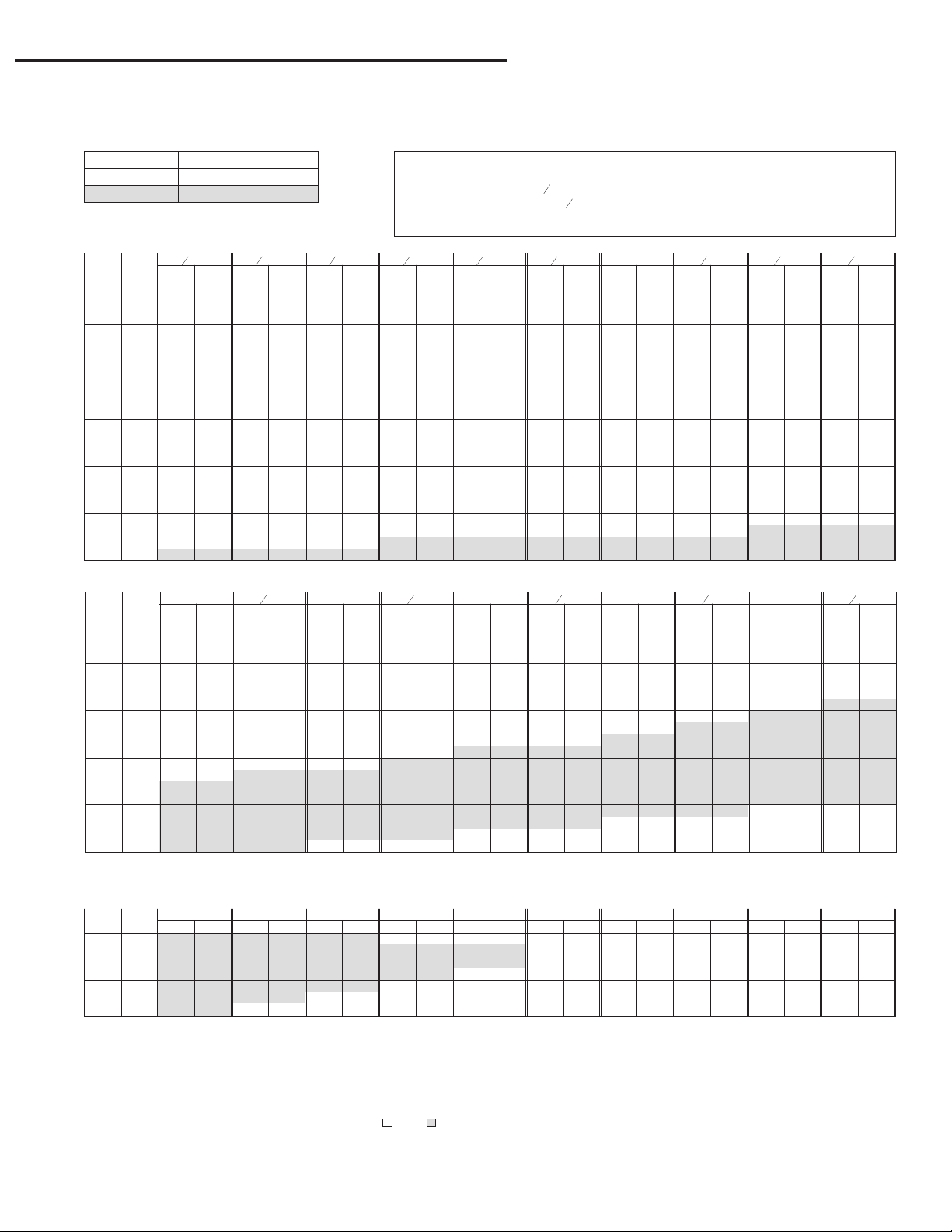
8100 SERIES
MAXIMUM CLASS OPERATING RPM
FAN TEMPERATURE
SIZE 8120 -20° to 150°F -29° to66°C
CLASS I 2183
CLASS II 2848
1
"SP
VOL
OUT
CFM
VEL
1392 600
1624 700 550 0.11 605 0.14 656 0.18 704 0.22
1856 800 597 0.13 647 0.17 696 0.22 740 0.26 781 0.31 824 0.35 865 0.40
2088 900 646 0.16 693 0.21 736 0.26 780 0.31 820 0.36 858 0.41 894 0.46 968 0.56
2320 1000 695 0.20 741 0.25 782 0.30 821 0.36 860 0.41 897 0.47 931 0.52 998 0.64 1065 0.75
2552 1100 746 0.24 790 0.30 829 0.36 866 0.41 901 0.47 937 0.53 971 0.59 1034 0.72 1094 0.84 1156 0.96
2784 1200 797 0.29 839 0.35 877 0.42 913 0.48 946 0.54 978 0.61 1011 0.67 1074 0.80 1131 0.94 1185 1.07
3016 1300 850 0.34 889 0.41 926 0.48 961 0.55 993 0.62 1024 0.68 1053 0.75 1114 0.89 1170 1.04 1223 1.18
3248 1400 903 0.41 941 0.48 976 0.55 1009 0.63 1041 0.70 1071 0.77 1099 0.85 1154 1.00 1210 1.15 1262 1.30
3480 1500 956 0.48 992 0.55 1026 0.63 1059 0.71 1089 0.79 1118 0.87 1146 0.95 1199 1.11 1251 1.27 1302 1.43
3712 1600 1010 0.56 1045 0.64 1077 0.72 1109 0.80 1138 0.89 1167 0.98 1194 1.06 1245 1.23 1293 1.40 1342 1.57
3944 1700 1065 0.65 1098 0.73 1129 0.82 1159 0.91 1188 1.00 1215 1.09 1242 1.18 1292 1.36 1339 1.53 1384 1.72
4176 1800 1120 0.75 1151 0.84 1181 0.93 1210 1.02 1238 1.11 1265 1.21 1291 1.31 1340 1.50 1386 1.68 1429 1.87
4408 1900 1175 0.85 1205 0.95 1234 1.05 1262 1.14 1289 1.24 1315 1.34 1340 1.44 1388 1.65 1433 1.84 1476 2.04
4640 2000 1231 0.97 1259 1.08 1287 1.18 1314 1.28 1340 1.38 1365 1.49 1390 1.59 1437 1.81 1481 2.02 1523 2.22
5104 2200 1343 1.25 1369 1.36 1394 1.48 1420 1.59 1444 1.70 1468 1.81 1491 1.92 1536 2.15 1578 2.39 1618 2.62
5568 2400 1455 1.57 1480 1.70 1503 1.82 1526 1.94 1550 2.06 1572 2.19 1594 2.31 1636 2.56 1677 2.81 1716 3.07
6032 2600 1569 1.95 1591 2.08 1613 2.22 1635 2.36 1656 2.49 1678 2.62 1699 2.75 1739 3.02 1778 3.29 1815 3.56
6496 2800 1683 2.39 1704 2.53 1724 2.68 1744 2.83 1764 2.98 1785 3.11 1804 3.25 1843 3.54 1880 3.82 1915 4.11
6960 3000 1797 2.89 1817 3.05 1836 3.20 1855 3.36 1874 3.52 1892 3.68 1911 3.82 1948 4.12 1983 4.43 2018 4.74
7424 3200 1911 3.46 1930 3.63 1948 3.80 1966 3.96 1984 4.13 2002 4.30 2019 4.47 2054 4.78 2088 5.11 2121 5.43
7888 3400 2026 4.11 2044 4.29 2061 4.46 2078 4.64 2095 4.82 2112 4.99 2128 5.17 2161 5.52 2194 5.86 2225 6.20
8352 3600 2141 4.84 2158 5.02 2175 5.20 2191 5.39 2207 5.58 2223 5.77 2238 5.96 2269 6.33 2300 6.69 2331 7.05
8816 3800 2257 5.64 2273 5.84 2288 6.03 2304 6.23 2319 6.42 2334 6.62 2349 6.82 2378 7.22 2408 7.61 2437 7.99
4
RPM BHP RPM BHP RPM BHP RPM BHP RPM BHP RPM BHP RPM BHP RPM BHP RPM BHP RPM BHP
•506 •0.08 •566 •0.12 •622 •0.15 •674 •0.19
3
"SP
8
1
2
"SP
Wheel Diameter 20 inches 508 mm
Wheel Circumference 5.24 feet 1.597m
Inlet Diameter/Area
Outlet Size/Area 21 x
Tip Speed 5.24 x RPM ft./minute 1.597x RPM m/minute
Maximum BHP .67 x (RPM 1000)
5
"SP
8
SINGLE WIDTH
SINGLE INLET
15
inches dia./2.58 sq. ft. 557 mm/.2397 m
21
16
13
inches I.D./2.32 sq. ft. 533 x 402 mm/.2155 m
15
16
3
BHP .4996 x (RPM 1000)3kW
3
"SP
4
•751 •0.26 •795 •0.30 •839 •0.35
7
"SP
8
"SP
1
SIZE 8120
1
"SP
1
4
•939 •0.49
1
"SP
1
2
•1036 •0.66
2
2
1
•1126 •0.86
3
"SP
4
1
"SP
VOL
OUT
CFM
VEL
3016 1300 1273 1.33 1376 1.62
3248 1400 1311 1.46 1406 1.78 1500 2.09
3480 1500 1350 1.60 1440 1.94 1530 2.27 1617 2.61
3712 1600 1390 1.74 1479 2.10 1561 2.46 1646 2.82 1727 3.18
3944 1700 1431 1.90 1518 2.27 1599 2.65 1676 3.04 1756 3.42 1832 3.80 1904 4.18
4176 1800 1472 2.07 1558 2.45 1638 2.85 1713 3.26 1786 3.67 1861 4.07 1933 4.47 2001 4.88
4408 1900 1517 2.24 1599 2.65 1678 3.06 1752 3.49 1821 3.92 1891 4.35 1962 4.77 2030 5.19 2095 5.62
4640 2000 1563 2.43 1640 2.86 1718 3.29 1791 3.73 1860 4.17 1925 4.63 1992 5.08 2060 5.52 2124 5.97 2187 6.42
5104 2200 1657 2.85 1730 3.31 1799 3.78 1871 4.25 1938 4.73 2003 5.22 2064 5.71 2123 6.22 2184 6.71 2245 7.19
5568 2400 1753 3.33 1824 3.82 1890 4.32 1953 4.83 2019 5.34 2082 5.86 2142 6.39 2200 6.92 2256 7.46 2310 8.01
6032 2600 1851 3.84 1919 4.39 1983 4.92 2044 5.46 2103 6.02 2163 6.57 2222 7.13 2279 7.69 2334 8.27 2387 8.84
6496 2800 1950 4.41 2016 5.01 2079 5.59 2138 6.17 2194 6.75 2249 7.35 2304 7.94 2360 8.54 2414 9.14 2466 9.75
6960 3000 2051 5.05 2115 5.68 2175 6.33 2233 6.94 2288 7.56 2341 8.18 2392 8.82 2441 9.46 2494 10.09 2546 10.73
7424 3200 2153 5.76 2214 6.42 2273 7.10 2329 7.79 2383 8.44 2434 9.10 2484 9.76 2532 10.44 2579 11.12 2627 11.80
7888 3400 2256 6.55 2315 7.25 2372 7.96 2427 8.68 2479 9.42 2529 10.10 2578 10.80 2625 11.50 2671 12.21 2715 12.93
8352 3600 2360 7.41 2418 8.15 2472 8.89 2525 9.65 2576 10.42 2625 11.19 2673 11.92 2719 12.65 2764 13.39 2807 14.14
8816 3800 2465 8.37 2521 9.13 2574 9.91 2625 10.70 2675 11.51 2723 12.32 2769 13.14 2814 13.90
9280 4000 2571 9.41 2625 10.21 2676 11.03 2726 11.85 2774 12.68 2821 13.53
9744 4200 2678 10.55 2730 11.39 2780 12.23 2828 13.09
10208 4400 2786 11.79 2836 12.66
VOL
OUT
CFM
VEL
5104 2200 2305 7.68 2419 8.67 •2526 •9.66
5568 2400 2364 8.56 2477 9.61 2584 10.68 •2684 •11.75 •2781 •12.85
6032 2600 2438 9.43 2537 10.62 2642 11.76 2742 12.90 2838 14.06
6496 2800 2516 10.36 2613 11.62 2705 12.89 2801 14.13
6960 3000 2596 11.38 2691 12.69 2782 14.02
7424 3200 2676 12.47 2770 13.84
7888 3400 2758 13.65
2
RPM BHP RPM BHP RPM BHP RPM BHP RPM BHP RPM BHP RPM BHP RPM BHP RPM BHP RPM BHP
"SP
7
RPM BHP RPM BHP RPM BHP RPM BHP RPM BHP RPM BHP RPM BHP RPM BHP RPM BHP RPM BHP
2
"SP
8
"SP
2
"SP
3
•1471 •1.92
"SP
9
1
"SP
3
2
•1588 •2.41 1675 2.77
"SP
10
"SP
4
•1698 •2.95 1778 3.32
"SP
11
1
"SP
4
2
"SP
5
•1803 •3.54 •1875 •3.91
12
"SP
13
"SP
1
"SP
5
2
•1972 •4.57
"SP
14
"SP
6
•2067 •5.29 2134 5.76
"SP
15
1
"SP
6
2
•2158 •6.05
"SP
16
• Approximate Max. Static Efficiency and Quietest Selection. CL. I CL. II
The standard AMCA class range is shown by the shaded areas. Standard carbonsteel fans may beused up to theMaximum Design RPM aslisted above for eachfan class.
For minimum motor size required see “Fan Starting Requirements,” page 7.
Performance certified is for Installation Type B: Free Inlet, Ducted Outlet. Power rating (BHP) does not include transmission losses. Performance ratings do not include the effects of
appurtenances (accessories).
All capacities listed above are based on standard Air Density of 0.075 Lbs./Cu. Ft. at 70°F & 0 Ft. elevation (1.2 kg/m3at 21.1°C&0m).
11
Page 12

8100 SERIES
SINGLE WIDTH
SIZE 8122
"SP
1
22
4
3
24
16
5
23
16
Wheel Diameter
Wheel Circumference 5.83 feet 1.777 m
Inlet Diameter/Area
Outlet Size/Area
Tip Speed 5.83 x RPM ft./minute 1.777 x RPM m/minute
Maximum BHP 1.15 x (RPM 1000)
1
VOL
OUT
CFM
VEL
1692 600
1974 700 489 0.13 540 0.17 585 0.22 629 0.27
2256 800 531 0.16 576 0.21 620 0.26 660 0.32 698 0.37 737 0.43
2538 900 573 0.20 616 0.25 656 0.31 695 0.37 731 0.43 765 0.49 800 0.56 866 0.68
2820 1000 617 0.24 658 0.30 696 0.37 731 0.43 767 0.50 800 0.56 831 0.63 892 0.77 952 0.91
3102 1100 661 0.29 701 0.36 737 0.43 770 0.50 802 0.57 835 0.64 866 0.72 923 0.87 978 1.02 1034 1.17
3384 1200 707 0.34 745 0.42 779 0.50 812 0.57 842 0.65 871 0.73 901 0.81 957 0.97 1009 1.13 1060 1.30
3666 1300 753 0.41 789 0.49 822 0.58 854 0.66 883 0.74 911 0.82 937 0.91 993 1.08 1043 1.25 1091 1.43
3948 1400 799 0.48 834 0.57 866 0.66 896 0.75 925 0.84 952 0.93 978 1.02 1028 1.20 1079 1.38 1125 1.57
4230 1500 846 0.57 879 0.66 910 0.75 940 0.85 967 0.95 994 1.04 1019 1.14 1066 1.33 1114 1.53 1161 1.73
4512 1600 894 0.66 926 0.76 955 0.86 984 0.96 1010 1.07 1036 1.17 1061 1.27 1107 1.47 1151 1.68 1196 1.89
4794 1700 942 0.77 972 0.87 1001 0.98 1028 1.08 1054 1.19 1079 1.30 1103 1.41 1148 1.63 1191 1.84 1232 2.07
5076 1800 990 0.88 1019 0.99 1047 1.10 1073 1.22 1098 1.33 1123 1.45 1146 1.57 1190 1.79 1232 2.02 1272 2.25
5358 1900 1039 1.01 1066 1.13 1093 1.24 1118 1.36 1143 1.48 1167 1.60 1189 1.73 1233 1.97 1274 2.21 1312 2.45
5640 2000 1088 1.15 1114 1.28 1140 1.40 1164 1.52 1188 1.65 1211 1.77 1233 1.90 1276 2.16 1316 2.42 1354 2.67
6204 2200 1187 1.47 1211 1.61 1234 1.75 1257 1.88 1280 2.02 1301 2.16 1322 2.29 1363 2.58 1401 2.86 1438 3.14
6768 2400 1286 1.85 1308 2.00 1330 2.16 1351 2.31 1372 2.45 1393 2.60 1413 2.75 1451 3.05 1488 3.36 1523 3.67
7332 2600 1386 2.30 1407 2.46 1427 2.63 1447 2.79 1466 2.95 1486 3.11 1505 3.27 1542 3.59 1577 3.92 1610 4.26
7896 2800 1487 2.81 1506 2.99 1525 3.17 1543 3.35 1562 3.52 1580 3.69 1598 3.86 1633 4.21 1667 4.56 1699 4.91
8460 3000 1588 3.40 1606 3.59 1623 3.78 1641 3.97 1658 4.17 1675 4.35 1692 4.54 1725 4.90 1758 5.27 1789 5.65
9024 3200 1689 4.08 1706 4.28 1722 4.48 1739 4.68 1755 4.89 1771 5.09 1787 5.29 1819 5.68 1850 6.07 1880 6.47
9588 3400 1790 4.83 1806 5.05 1822 5.26 1838 5.48 1853 5.69 1868 5.91 1883 6.13 1913 6.54 1943 6.96 1972 7.37
10152 3600 1892 5.69 1907 5.91 1922 6.13 1937 6.36 1951 6.59 1966 6.82 1980 7.05 2008 7.50 2037 7.94 2064 8.38
10716 3800 1993 6.63 2008 6.87 2022 7.11 2036 7.34 2050 7.58 2064 7.83 2078 8.07 2104 8.56 2131 9.02 2158 9.48
4
RPM BHP RPM BHP RPM BHP RPM BHP RPM BHP RPM BHP RPM BHP RPM BHP RPM BHP RPM BHP
•451 •0.10 •505 •0.14 •556 •0.18 •603 •0.22
SINGLE INLET
inches 565 mm
inches dia./3.14 sq. ft. 614 mm/.2917 m
7
x
inches I.D./2.82 sq. ft. 592 x 443 mm/.2620 m
17
16
3
BHP .8576 x (RPM 1000)3kW
3
8
"SP
1
"SP
2
5
"SP
8
3
4
•672 •0.32 •711 •0.37
"SP
2
2
7
"SP
8
MAXIMUM CLASS OPERATING RPM
FAN TEMPERATURE
SIZE 8122 -20° to 150°F -29° to66°C
CLASS I 1962
CLASS II 2560
"SP
1
1
"SP
1
4
•773 •0.48 •843 •0.60
1
"SP
1
2
•927 •0.80
3
"SP
1
4
•1008 •1.05
1
"SP
VOL
OUT
CFM
VEL
3666 1300 1137 1.61 1231 1.97
3948 1400 1170 1.77 1257 2.15 1342 2.53
4230 1500 1204 1.93 1285 2.34 1368 2.75 1446 3.16
4512 1600 1239 2.10 1319 2.54 1394 2.98 1472 3.41 1545 3.85
4794 1700 1275 2.29 1354 2.74 1427 3.21 1498 3.68 1570 4.14 1639 4.60
5076 1800 1311 2.49 1389 2.96 1461 3.45 1528 3.95 1597 4.44 1664 4.92 1729 5.41 1790 5.91
5358 1900 1349 2.70 1425 3.19 1496 3.70 1563 4.22 1625 4.75 1691 5.26 1755 5.77 1816 6.29 1875 6.81
5640 2000 1390 2.92 1461 3.44 1531 3.97 1597 4.50 1659 5.05 1718 5.61 1781 6.15 1842 6.69 1900 7.23 1956 7.78
6204 2200 1473 3.42 1539 3.98 1603 4.55 1667 5.13 1728 5.71 1786 6.31 1842 6.91 1895 7.53 1952 8.12 2008 8.71
6768 2400 1557 3.98 1621 4.58 1681 5.20 1739 5.82 1799 6.44 1856 7.08 1911 7.72 1963 8.37 2013 9.03 2062 9.71
7332 2600 1643 4.59 1705 5.26 1763 5.91 1818 6.57 1871 7.25 1927 7.92 1981 8.60 2032 9.29 2082 9.99 2129 10.70
7896 2800 1730 5.27 1790 6.00 1847 6.70 1900 7.41 1952 8.12 2001 8.85 2052 9.57 2103 10.30 2151 11.03 2199 11.78
8460 3000 1819 6.03 1877 6.80 1932 7.59 1984 8.33 2034 9.08 2082 9.84 2128 10.62 2175 11.39 2223 12.16 2269 12.95
9024 3200 1909 6.87 1965 7.68 2018 8.51 2069 9.34 2117 10.13 2164 10.93 2209 11.74 2253 12.56 2295 13.39 2341 14.21
9588 3400 2000 7.79 2053 8.65 2105 9.52 2154 10.40 2202 11.28 2247 12.11 2291 12.96 2334 13.82 2375 14.69 2416 15.57
10152 3600 2091 8.82 2143 9.71 2193 10.62 2241 11.55 2287 12.48 2332 13.41 2375 14.29 2417 15.19 2457 16.09 2496 17.01
10716 3800 2184 9.94 2234 10.88 2283 11.83 2329 12.79 2374 13.77 2418 14.76 2460 15.73 2500 16.66 2540 17.61
11280 4000 2277 11.17 2326 12.15 2373 13.14 2418 14.15 2462 15.16 2504 16.19 2545 17.24
11844 4200 2371 12.51 2418 13.53 2464 14.57 2508 15.61 2550 16.67
12408 4400 2466 13.97 2511 15.03 2555 16.11
VOL
OUT
CFM
VEL
6204 2200 2062 9.30 •2164 •10.51 •2260 •11.73
6768 2400 2114 10.35 2215 11.64 2311 12.94 •2402 •14.25 •2492 •15.69
7332 2600 2176 11.42 2268 12.85 2363 14.23 2453 15.63 2539 17.05
7896 2800 2244 12.53 2332 14.06 2415 15.62 2505 17.10
8460 3000 2314 13.74 2400 15.34 2482 16.97 2560 18.64
9024 3200 2385 15.04 2470 16.71 2550 18.42
9588 3400 2457 16.44 2540 18.19
10152 3600 2535 17.93
2
RPM BHP RPM BHP RPM BHP RPM BHP RPM BHP RPM BHP RPM BHP RPM BHP RPM BHP RPM BHP
"SP
7
RPM BHP RPM BHP RPM BHP RPM BHP RPM BHP RPM BHP RPM BHP RPM BHP RPM BHP RPM BHP
2
2
"SP
8
"SP
"SP
3
•1316 •2.33
"SP
9
1
"SP
3
2
•1421 •2.92
"SP
10
"SP
4
•1519 •3.58
"SP
11
1
"SP
4
2
•1613 •4.29 1683 4.80
"SP
12
"SP
5
•1703 •5.07 •1767 •5.57
"SP
13
1
"SP
5
2
"SP
6
•1849 •6.41
"SP
14
15
"SP
1
"SP
6
2
•1931 •7.34
"SP
16
• Approximate Max. Static Efficiency and Quietest Selection. CL. I CL. II
The standard AMCA class range is shown by the shaded areas. Standard carbonsteel fans may beused up to theMaximum Design RPM aslisted above for eachfan class.
For minimum motor size required see “Fan Starting Requirements,” page 7.
Performance certified is for Installation Type B: Free Inlet, Ducted Outlet. Power rating (BHP) does not include transmission losses. Performance ratings do not include the effects of
appurtenances (accessories).
All capacities listed above are based on standard Air Density of 0.075 Lbs./Cu. Ft. at 70°F & 0 Ft. elevation (1.2 kg/m3at 21.1°C&0m).
12
Page 13

8100 SERIES
MAXIMUM CLASS OPERATING RPM
FAN TEMPERATURE
SIZE 8124 -20° to 150°F -29° to66°C
CLASS I 1782
CLASS II 2325
1
"SP
VOL
OUT
CFM
VEL
2076 600
2422 700 447 0.16 493 0.21 534 0.27 573 0.33
2768 800 486 0.20 526 0.26 566 0.32 603 0.39 636 0.46 672 0.53
3114 900 525 0.24 564 0.31 599 0.38 635 0.46 668 0.53 698 0.61 729 0.68 789 0.83
3460 1000 565 0.30 602 0.37 636 0.45 668 0.53 700 0.61 730 0.69 758 0.78 813 0.95 868 1.12
3806 1100 606 0.36 642 0.44 674 0.53 704 0.62 733 0.70 763 0.79 790 0.88 842 1.07 892 1.25 942 1.44
4152 1200 648 0.43 682 0.52 713 0.62 742 0.71 770 0.80 796 0.90 823 1.00 874 1.19 921 1.39 966 1.60
4498 1300 690 0.51 723 0.61 753 0.71 781 0.82 808 0.92 833 1.02 857 1.12 906 1.33 953 1.54 996 1.76
4844 1400 733 0.60 764 0.71 793 0.82 821 0.93 846 1.04 871 1.15 894 1.26 939 1.48 985 1.71 1027 1.94
5190 1500 776 0.71 806 0.82 834 0.94 860 1.06 885 1.18 909 1.29 932 1.41 975 1.64 1018 1.88 1060 2.13
5536 1600 820 0.83 849 0.95 875 1.07 901 1.19 925 1.32 948 1.45 971 1.57 1013 1.82 1052 2.08 1092 2.33
5882 1700 864 0.96 891 1.08 917 1.21 942 1.35 965 1.48 988 1.61 1010 1.75 1051 2.01 1089 2.28 1126 2.55
6228 1800 909 1.10 935 1.24 960 1.37 983 1.51 1006 1.65 1028 1.79 1049 1.94 1089 2.22 1127 2.50 1163 2.78
6574 1900 954 1.26 978 1.41 1002 1.55 1025 1.69 1047 1.84 1069 1.99 1089 2.14 1128 2.45 1165 2.74 1200 3.03
6920 2000 999 1.44 1022 1.59 1045 1.74 1067 1.89 1089 2.05 1110 2.20 1130 2.36 1168 2.68 1204 2.99 1238 3.30
7612 2200 1090 1.84 1111 2.01 1132 2.18 1153 2.35 1173 2.51 1193 2.68 1212 2.85 1248 3.19 1283 3.55 1316 3.89
8304 2400 1181 2.32 1201 2.50 1220 2.69 1240 2.88 1259 3.05 1277 3.24 1295 3.42 1330 3.79 1363 4.17 1395 4.55
8996 2600 1273 2.88 1292 3.08 1310 3.28 1327 3.49 1345 3.68 1363 3.87 1380 4.07 1413 4.47 1444 4.87 1475 5.28
9688 2800 1366 3.52 1383 3.74 1400 3.96 1416 4.18 1433 4.40 1449 4.61 1465 4.81 1497 5.24 1527 5.66 1557 6.10
10380 3000 1458 4.27 1474 4.50 1490 4.73 1506 4.96 1521 5.20 1537 5.43 1552 5.66 1582 6.10 1611 6.56 1639 7.02
11072 3200 1551 5.11 1566 5.36 1582 5.60 1596 5.85 1611 6.10 1625 6.36 1639 6.60 1668 7.08 1696 7.56 1723 8.04
11764 3400 1644 6.06 1659 6.32 1673 6.58 1687 6.85 1701 7.11 1714 7.38 1728 7.65 1755 8.16 1782 8.67 1807 9.18
12456 3600 1738 7.13 1751 7.40 1765 7.68 1778 7.96 1791 8.24 1804 8.52 1817 8.80 1842 9.36 1868 9.90 1893 10.43
13148 3800 1831 8.32 1844 8.61 1857 8.90 1870 9.19 1882 9.49 1895 9.78 1907 10.08 1931 10.68 1955 11.25 1979 11.81
4
RPM BHP RPM BHP RPM BHP RPM BHP RPM BHP RPM BHP RPM BHP RPM BHP RPM BHP RPM BHP
•412 •0.12 •461 •0.17 •507 •0.23 •550 •0.28
3
"SP
8
1
2
"SP
Wheel Diameter
Wheel Circumference 6.41 feet 1.954 m
Inlet Diameter/Area
Outlet Size/Area
Tip Speed 6.41 x RPM ft./minute 1.954 x RPM m/minute
Maximum BHP 1.80 x (RPM 1000)
5
"SP
8
SINGLE WIDTH
SINGLE INLET
1
inches 622 mm
24
2
3
inches dia./3.98 sq. ft. 691 mm/.3697 m
27
16
11
x
25
19
16
3
"SP
4
•612 •0.39 •648 •0.45
7
"SP
8
SIZE 8124
5
inches I.D./3.46 sq. ft. 652 x 491 mm/.3214 m
16
3
BHP 1.342 x (RPM 1000)3kW
"SP
1
1
"SP
1
4
•705 •0.59 •766 •0.73
1
"SP
1
2
•844 •0.99
2
•918 •1.29
2
3
"SP
1
4
1
"SP
VOL
OUT
CFM
VEL
4498 1300 1037 1.99 1122 2.42
4844 1400 1067 2.17 1146 2.65 1223 3.11
5190 1500 1099 2.37 1173 2.88 1247 3.38 1317 3.89
5536 1600 1132 2.59 1204 3.12 1271 3.67 1341 4.20 1407 4.73
5882 1700 1164 2.82 1236 3.38 1302 3.95 1365 4.53 1431 5.09 1493 5.66 1552 6.23
6228 1800 1198 3.07 1268 3.65 1334 4.24 1395 4.85 1455 5.46 1517 6.06 1575 6.66 1631 7.26
6574 1900 1234 3.33 1301 3.94 1366 4.56 1426 5.19 1483 5.84 1541 6.48 1599 7.10 1654 7.74 1708 8.37
6920 2000 1271 3.61 1334 4.25 1398 4.89 1458 5.55 1514 6.22 1568 6.90 1623 7.57 1678 8.23 1731 8.89 1782 9.56
7612 2200 1347 4.23 1407 4.92 1464 5.62 1523 6.32 1578 7.04 1631 7.76 1681 8.51 1729 9.26 1779 9.99 1830 10.71
8304 2400 1425 4.93 1483 5.67 1537 6.42 1589 7.18 1643 7.95 1695 8.72 1744 9.51 1791 10.30 1837 11.11 1881 11.94
8996 2600 1504 5.69 1560 6.51 1613 7.31 1663 8.12 1710 8.95 1760 9.77 1809 10.60 1855 11.45 1900 12.30 1944 13.17
9688 2800 1585 6.54 1639 7.43 1690 8.30 1738 9.16 1785 10.03 1829 10.92 1875 11.81 1920 12.70 1965 13.60 2007 14.51
10380 3000 1666 7.48 1719 8.43 1768 9.39 1815 10.31 1860 11.23 1904 12.16 1946 13.11 1987 14.06 2030 15.01 2072 15.96
11072 3200 1749 8.53 1800 9.53 1848 10.54 1894 11.57 1937 12.54 1980 13.51 2020 14.51 2060 15.51 2098 16.53 2138 17.54
11764 3400 1833 9.69 1881 10.74 1928 11.80 1972 12.88 2015 13.97 2056 15.00 2096 16.03 2135 17.08 2172 18.14 2209 19.22
12456 3600 1917 10.97 1964 12.07 2009 13.18 2052 14.31 2094 15.46 2134 16.61 2173 17.69 2211 18.79 2247 19.89 2283 21.01
13148 3800 2002 12.38 2048 13.53 2091 14.69 2133 15.87 2174 17.07 2213 18.28 2251 19.49 2288 20.63 2324 21.78
13840 4000 2088 13.92 2132 15.12 2174 16.33 2215 17.56 2255 18.81 2293 20.07
14532 4200 2175 15.60 2217 16.85 2258 18.12 2298 19.40
15224 4400 2262 17.43 2303 18.73
VOL
OUT
CFM
VEL
7612 2200 1879 11.44 •1971 •12.91 •2059 •14.40
8304 2400 1926 12.74 2019 14.31 2106 15.90 •2188 •17.52 •2266 •19.15
8996 2600 1985 14.04 2067 15.82 2153 17.51 2235 19.22 2313 20.95
9688 2800 2049 15.43 2128 17.30 2203 19.21 2283 21.04
10380 3000 2113 16.93 2191 18.89 2265 20.88
11072 3200 2178 18.55 2255 20.60
11764 3400 2245 20.30 2320 22.44
12456 3600 2318 22.14
2
RPM BHP RPM BHP RPM BHP RPM BHP RPM BHP RPM BHP RPM BHP RPM BHP RPM BHP RPM BHP
"SP
7
RPM BHP RPM BHP RPM BHP RPM BHP RPM BHP RPM BHP RPM BHP RPM BHP RPM BHP RPM BHP
2
2
"SP
8
"SP
"SP
3
•1199 •2.86
"SP
9
1
"SP
3
2
•1294 •3.59
"SP
10
"SP
4
•1384 •4.39 1450 4.97
"SP
11
1
"SP
4
2
•1469 •5.28 •1530 •5.85
"SP
12
5
13
"SP
"SP
1
"SP
5
2
•1608 •6.81
"SP
14
"SP
6
•1684 •7.88 1742 8.62
"SP
15
1
"SP
6
2
•1759 •9.02
"SP
16
• Approximate Max. Static Efficiency and Quietest Selection. CL. I CL. II
The standard AMCA class range is shown by the shaded areas. Standard carbonsteel fans may beused up to theMaximum Design RPM aslisted above for eachfan class.
For minimum motor size required see “Fan Starting Requirements,” page 7.
Performance certified is for Installation Type B: Free Inlet, Ducted Outlet. Power rating (BHP) does not include transmission losses. Performance ratings do not include the effects of
appurtenances (accessories).
All capacities listed above are based on standard Air Density of 0.075 Lbs./Cu. Ft. at 70°F & 0 Ft. elevation (1.2 kg/m3at 21.1°C&0m).
13
Page 14

8100 SERIES
SINGLE WIDTH
SIZE 8127
Wheel Diameter 27 inches 686 mm
Wheel Circumference 7.07 feet 2.155 m
Inlet Diameter/Area
Outlet Size/Area
Tip Speed 7.07 x RPM ft./minute 2.155 x RPM m/minute
Maximum BHP 3.05 x (RPM 1000)
VOL
OUT
CFM
VEL
2520 600
2940 700 386 0.17 427 0.23 465 0.30
3360 800 418 0.21 455 0.28 490 0.36 523 0.43
3780 900 451 0.26 486 0.34 518 0.42 550 0.50 579 0.59 609 0.67
4200 1000 486 0.32 518 0.40 549 0.49 577 0.58 606 0.67 633 0.76 659 0.86
4620 1100 522 0.38 552 0.47 581 0.57 608 0.67 634 0.77 660 0.87 685 0.97 733 1.18
5040 1200 558 0.46 586 0.56 614 0.66 640 0.77 664 0.87 688 0.98 712 1.09 758 1.31 802 1.54
5460 1300 595 0.55 622 0.65 647 0.76 672 0.87 696 0.99 719 1.11 741 1.22 784 1.46 826 1.70 866 1.94
5880 1400 632 0.64 658 0.76 682 0.88 705 0.99 728 1.12 750 1.24 771 1.37 812 1.62 853 1.87 891 2.13
6300 1500 669 0.75 694 0.88 718 1.00 740 1.13 761 1.26 783 1.39 803 1.52 842 1.79 880 2.06 917 2.33
6720 1600 707 0.87 731 1.02 754 1.14 775 1.28 795 1.41 816 1.55 835 1.69 873 1.98 909 2.26 944 2.55
7140 1700 745 1.01 768 1.16 790 1.30 811 1.44 830 1.58 849 1.73 868 1.87 905 2.17 940 2.48 973 2.78
7560 1800 784 1.16 806 1.32 827 1.47 847 1.62 866 1.77 884 1.92 902 2.07 938 2.38 971 2.71 1004 3.03
7980 1900 822 1.32 843 1.49 864 1.66 883 1.82 901 1.97 919 2.13 936 2.29 970 2.61 1004 2.95 1035 3.29
8400 2000 861 1.51 881 1.68 901 1.86 920 2.03 937 2.19 955 2.36 971 2.52 1004 2.86 1036 3.21 1067 3.56
9240 2200 939 1.93 958 2.12 976 2.31 994 2.51 1011 2.70 1027 2.87 1043 3.05 1073 3.42 1102 3.79 1132 4.17
10080 2400 1018 2.42 1035 2.63 1052 2.84 1069 3.05 1085 3.26 1100 3.47 1115 3.67 1144 4.06 1172 4.45 1199 4.86
10920 2600 1097 3.00 1113 3.22 1129 3.45 1144 3.68 1160 3.91 1174 4.14 1189 4.37 1216 4.79 1243 5.21 1268 5.64
11760 2800 1176 3.67 1191 3.91 1206 4.15 1221 4.39 1235 4.64 1249 4.89 1263 5.14 1289 5.62 1315 6.07 1339 6.53
12600 3000 1255 4.44 1270 4.70 1284 4.95 1298 5.21 1312 5.47 1325 5.74 1338 6.00 1363 6.54 1388 7.03 1411 7.52
13440 3200 1335 5.32 1349 5.59 1362 5.86 1375 6.13 1388 6.41 1401 6.69 1413 6.97 1438 7.54 1461 8.11 1484 8.62
14280 3400 1415 6.30 1428 6.59 1441 6.88 1453 7.17 1466 7.46 1478 7.75 1490 8.05 1513 8.65 1535 9.26 1557 9.85
15120 3600 1496 7.41 1508 7.71 1520 8.01 1532 8.32 1543 8.63 1555 8.94 1566 9.25 1588 9.88 1610 10.52 1631 11.16
15960 3800 1576 8.64 1588 8.96 1599 9.28 1610 9.60 1622 9.92 1632 10.25 1643 10.58 1665 11.24 1685 11.90 1706 12.58
1
RPM BHP RPM BHP RPM BHP RPM BHP RPM BHP RPM BHP RPM BHP RPM BHP RPM BHP RPM BHP
•356 •0.14 •401 •0.19 •446 •0.25 494 0.32
"SP
4
11
29
16
3
28
8
SINGLE INLET
inches dia./4.75 sq. ft. 754 mm/.4413 m
5
x
inches I.D./4.20 sq. ft. 721 x541 mm/.3902 m
21
16
3
BHP 2.274 x (RPM 1000)3kW
3
8
"SP
1
"SP
2
5
"SP
8
•501 •0.37 544 0.45
3
"SP
4
•556 •0.51 •591 •0.59 627 0.68
2
2
7
"SP
8
MAXIMUM CLASS OPERATING RPM
FAN TEMPERATURE
SIZE 8127 -20° to 150°F -29° to66°C
CLASS I 1548
CLASS II 2020
"SP
1
•637 •0.76 702 0.96
1
"SP
1
4
•710 •1.05 770 1.28 825 1.51
1
"SP
1
2
•779 •1.39 833 1.63
3
"SP
1
4
•844 •1.77
1
"SP
VOL
OUT
CFM
VEL
5880 1400 928 2.40
6300 1500 953 2.61 1023 3.18
6720 1600 980 2.84 1046 3.44 1111 4.04 1181 4.72 1253 5.46
7140 1700 1007 3.09 1071 3.71 1133 4.35
7560 1800 1035 3.35 1098 4.00 1157 4.67 1216 5.35
7980 1900 1066 3.63 1125 4.31 1183 5.01 1238 5.72 1294 6.43
8400 2000 1097 3.92 1153 4.64 1210 5.36 1264 6.10 1316 6.85 1368 7.60 •1418 •8.37 •1478 •9.26 1537 10.18 1593 11.12
9240 2200 1160 4.56 1214 5.34 1265 6.13 1317 6.93 1367 7.73 1415 8.55 1463 9.37 1510 10.20 •1555 •11.04 •1608 •12.01
10080 2400 1226 5.27 1278 6.12 1327 6.98 1373 7.84 1421 8.70 1467 9.57 1512 10.45 1555 11.35 1599 12.24 1642 13.15
10920 2600 1293 6.08 1343 6.98 1390 7.90 1435 8.83 1478 9.75 1521 10.69 1565 11.63 1607 12.57 1648 13.53 1687 14.50
11760 2800 1363 6.99 1409 7.94 1454 8.91 1498 9.90 1540 10.90 1580 11.90 1619 12.91 1661 13.91 1700 14.92 1739 15.94
12600 3000 1434 8.01 1477 9.00 1520 10.03 1562 11.07 1603 12.13 1642 13.20 1680 14.27 1717 15.34 1754 16.42 1792 17.49
13440 3200 1506 9.14 1548 10.19 1588 11.26 1628 12.35 1667 13.47 1705 14.60 1742 15.74 1778 16.87 1813 18.01 1847 19.17
14280 3400 1578 10.39 1619 11.50 1658 12.62 1695 13.76 1733 14.92 1770 16.11 1806 17.31 1840 18.52 1874 19.72 1907 20.92
15120 3600 1651 11.78 1691 12.93 1728 14.11 1764 15.30 1799 16.51 1835 17.74 1870 18.99 1904 20.26 1937 21.54 1969 22.82
15960 3800 1725 13.26 1763 14.50 1800 15.73 1835 16.98 1869 18.24 1902 19.52 1936 20.82 1969 22.14 2001 23.47
16800 4000 1800 14.84 1837 16.22 1872 17.50 1906 18.80 1939 20.11 1971 21.44 2002 22.79
17640 4200 1875 16.56 1910 18.06 1944 19.42 1977 20.77 2009 22.14
18480 4400 1950 18.43 1984 19.99 2018 21.51
VOL
OUT
CFM
VEL
10080 2400 •1683 •14.06 1780 16.15 1876 18.36 1966 20.62
10920 2600 1728 15.47 •1806 •17.43 •1891 •19.60 1982 21.97
11760 2800 1776 16.97 1851 19.05 1924 21.16 •1997 •23.35
12600 3000 1829 18.57 1900 20.77 1969 23.00
13440 3200 1883 20.30 1952 22.60 2018 24.94
14280 3400 1940 22.14 2006 24.57
15120 3600 2001 24.08
2
RPM BHP RPM BHP RPM BHP RPM BHP RPM BHP RPM BHP RPM BHP RPM BHP RPM BHP RPM BHP
"SP
7
RPM BHP RPM BHP RPM BHP RPM BHP RPM BHP RPM BHP RPM BHP RPM BHP RPM BHP RPM BHP
"SP
2
2
•1002 •2.94 1087 3.58
"SP
8
"SP
3
•1095 •3.79 1173 4.48
"SP
9
1
"SP
3
2
•1193 •5.00 1261 5.74 1329 6.52 1394 7.33
"SP
10
"SP
4
•1272 •6.04 1337 6.83 1401 7.66 1463 8.51
"SP
11
1
"SP
4
2
"SP
5
•1346 •7.16 1409 8.01 1470 8.88 1529 9.78
12
"SP
13
"SP
1
"SP
5
2
"SP
14
6
15
"SP
"SP
1
"SP
6
2
"SP
16
• Approximate Max. Static Efficiency and Quietest Selection. CL. I CL. II
The standard AMCA class range is shown by the shaded areas. Standard carbonsteel fans may beused up to theMaximum Design RPM aslisted above for eachfan class.
For minimum motor size required see “Fan Starting Requirements,” page 7.
Performance certified is for Installation Type B: Free Inlet, Ducted Outlet. Power rating (BHP) does not include transmission losses. Performance ratings do not include the effects of
appurtenances (accessories).
All capacities listed above are based on standard Air Density of 0.075 Lbs./Cu. Ft. at 70°F & 0 Ft. elevation (1.2 kg/m3at 21.1°C&0m).
14
Page 15

8100 SERIES
MAXIMUM CLASS OPERATING RPM
FAN TEMPERATURE
SIZE 8130 -20° to 150°F -29° to66°C
CLASS I 1391
CLASS II 1818
1
"SP
VOL
OUT
CFM
VEL
3078 600 •350 •0.19 •394 •0.27 •433 •0.35 467 0.44 502 0.53 534 0.62 564 0.72 627 0.95 684 1.19 736 1.44
3591 700 378 0.23 419 0.32 457 0.42 •491 •0.51 522 0.61 551 0.71 581 0.82 636 1.05 689 1.29 741 1.56
4104 800 409 0.29 445 0.38 482 0.49 516 0.60 •546 •0.71 •574 •0.82 600 0.93 652 1.17 702 1.43 747 1.69
4617 900 442 0.35 476 0.46 507 0.57 540 0.69 571 0.81 598 0.93 •625 •1.06 673 1.31 719 1.58 764 1.86
5130 1000 475 0.43 508 0.55 538 0.67 566 0.80 595 0.92 623 1.06 649 1.19 •697 •1.47 740 1.74 781 2.03
5643 1100 509 0.51 541 0.65 569 0.78 595 0.91 621 1.05 648 1.19 674 1.34 721 1.63 •764 •1.93 804 2.24
6156 1200 544 0.61 574 0.76 601 0.90 627 1.04 651 1.19 674 1.34 699 1.50 746 1.81 789 2.14 •828 •2.46
6669 1300 579 0.73 608 0.88 634 1.04 659 1.19 682 1.35 704 1.51 725 1.67 771 2.01 814 2.36 853 2.70
7182 1400 615 0.86 642 1.02 667 1.18 691 1.36 714 1.52 735 1.69 756 1.86 796 2.21 838 2.58 878 2.96
7695 1500 651 1.00 677 1.18 701 1.35 724 1.53 746 1.71 767 1.89 787 2.07 825 2.44 864 2.82 903 3.22
8208 1600 688 1.17 712 1.35 736 1.54 758 1.73 779 1.92 800 2.12 819 2.30 856 2.69 890 3.08 928 3.50
8721 1700 725 1.35 748 1.54 770 1.74 792 1.94 813 2.15 832 2.35 851 2.55 887 2.96 921 3.37 954 3.81
9234 1800 762 1.55 784 1.76 805 1.96 826 2.17 846 2.38 866 2.61 884 2.82 919 3.25 952 3.68 984 4.13
9747 1900 800 1.78 821 2.00 841 2.21 861 2.43 880 2.65 899 2.88 917 3.11 952 3.57 984 4.02 1015 4.48
10260 2000 838 2.04 858 2.26 877 2.48 896 2.70 915 2.94 933 3.18 951 3.42 984 3.90 1016 4.38 1046 4.85
11286 2200 914 2.61 932 2.84 950 3.09 967 3.33 985 3.59 1002 3.84 1019 4.11 1051 4.64 1081 5.17 1110 5.69
12312 2400 990 3.29 1007 3.54 1024 3.81 1040 4.07 1056 4.34 1072 4.62 1088 4.90 1119 5.47 1148 6.05 1176 6.64
13338 2600 1067 4.08 1083 4.36 1099 4.65 1114 4.93 1129 5.22 1143 5.50 1158 5.80 1187 6.41 1215 7.02 1242 7.65
14364 2800 1144 5.00 1159 5.30 1174 5.61 1188 5.90 1202 6.21 1216 6.53 1230 6.85 1257 7.48 1284 8.14 1310 8.81
15390 3000 1222 6.06 1236 6.38 1250 6.71 1263 7.02 1277 7.36 1290 7.69 1303 8.03 1328 8.70 1354 9.40 1379 10.10
16416 3200 1299 7.25 1313 7.60 1326 7.94 1339 8.29 1352 8.65 1364 8.99 1376 9.34 1400 10.05 1424 10.78 1448 11.53
17442 3400 1377 8.61 1390 8.98 1402 9.33 1415 9.71 1427 10.08 1439 10.45 1450 10.81 1473 11.56 1495 12.32 1518 13.11
18468 3600 1455 10.12 1467 10.51 1479 10.89 1491 11.29 1502 11.66 1514 12.07 1525 12.46 1547 13.25 1568 14.05 1589 14.86
19494 3800 1534 11.83 1545 12.23 1556 12.62 1567 13.03 1578 13.44 1589 13.85 1600 14.27 1621 15.10 1642 15.96 1662 16.81
4
RPM BHP RPM BHP RPM BHP RPM BHP RPM BHP RPM BHP RPM BHP RPM BHP RPM BHP RPM BHP
3
"SP
8
1
2
"SP
Wheel Diameter 30 inches 762 mm
Wheel Circumference 7.85 feet 2.393 m
Inlet Diameter/Area
Outlet Size/Area
Tip Speed 7.85 x RPM ft./minute 2.393 x RPM m/minute
Maximum BHP 5.15 x (RPM 1000)
5
"SP
8
SINGLE WIDTH
SINGLE INLET
11
inches dia./5.76 sq. ft. 830 mm/.5351 m
32
16
7
x
23
16
3
"SP
4
7
"SP
8
SIZE 8130
1
inches I.D./5.13 sq. ft. 595 x 800 mm/.4766 m
31
2
3
BHP 3.840 x (RPM 1000)3kW
"SP
1
1
"SP
1
4
1
"SP
1
2
2
2
3
"SP
1
4
1
"SP
VOL
OUT
CFM
VEL
7182 1400 •915 •3.34 •982 •4.10 1043 4.88 1102 5.70 1162 6.57 1218 7.46 1271 8.38 1322 9.32 1378 10.36 1431 11.40
7695 1500 939 3.62 1006 4.43 1067 5.25 1124 6.10 1179 6.98 1235 7.91 1288 8.86 1338 9.82 1387 10.83 1436 11.86
8208 1600 964 3.92 1031 4.78 •1092 •5.65 1148 6.53 1201 7.44 1252 8.37 1305 9.36 1355 10.36 1404 11.40 1450 12.45
8721 1700 989 4.24 1056 5.15 1117 6.07 •1172 •6.98 1225 7.93 1274 8.88 1322 9.88 1372 10.91 1420 11.97 1467 13.07
9234 1800 1015 4.58 1081 5.53 1141 6.49 1197 7.46 •1249 •8.44 1298 9.43 1345 10.45 1390 11.50 1438 12.61 1484 13.72
9747 1900 1044 4.95 1106 5.92 1166 6.93 1222 7.97 1274 8.99 •1323 •10.02 1369 11.06 1414 12.15 1457 13.25 1501 14.39
10260 2000 1075 5.34 1131 6.34 1191 7.39 1246 8.45 1298 9.54 1347 10.62 •1393 •11.70 1438 12.83 1480 13.94 1521 15.09
11286 2200 1138 6.21 1191 7.29 1242 8.40 1296 9.53 1348 10.71 1397 11.91 1443 13.10 •1487 •14.28 •1529 •15.48 1569 16.68
12312 2400 1203 7.21 1254 8.35 1301 9.51 1347 10.71 1398 11.96 1446 13.22 1492 14.52 1536 15.82 1578 17.12 •1618 •18.40
13338 2600 1268 8.29 1318 9.54 1364 10.78 1408 12.05 1450 13.35 1497 14.69 1542 16.04 1585 17.41 1627 18.82 1668 20.26
14364 2800 1335 9.48 1383 10.86 1428 12.18 1471 13.52 1512 14.90 1551 16.28 1593 17.71 1636 19.17 1677 20.63 1717 22.13
15390 3000 1403 10.82 1449 12.26 1493 13.72 1534 15.12 1574 16.56 1613 18.05 1650 19.54 1687 21.04 1728 22.60 1767 24.15
16416 3200 1471 12.27 1516 13.81 1558 15.36 1599 16.90 1638 18.42 1675 19.93 1712 21.52 1747 23.10 1781 24.71 1818 26.33
17442 3400 1541 13.91 1584 15.51 1625 17.14 1665 18.83 1703 20.44 1739 22.03 1775 23.68 1809 25.32
18468 3600 1611 15.70 1653 17.39 1693 19.10 1731 20.83 1768 22.60 1804 24.31
19494 3800 1682 17.67 1722 19.41 1761 21.21 1798 23.02
20520 4000 1754 19.82 1792 21.63
VOL
OUT
CFM
VEL
12312 2400 •1657 •19.71 1731 22.36 1801 25.08
13338 2600 1706 21.64 •1780 •24.46
14364 2800 1756 23.66
15390 3000 1805 25.72
2
RPM BHP RPM BHP RPM BHP RPM BHP RPM BHP RPM BHP RPM BHP RPM BHP RPM BHP RPM BHP
"SP
7
RPM BHP RPM BHP RPM BHP RPM BHP RPM BHP RPM BHP RPM BHP RPM BHP RPM BHP RPM BHP
"SP
2
2
"SP
8
"SP
3
"SP
9
1
"SP
3
2
"SP
10
4
11
"SP
"SP
1
"SP
4
2
"SP
12
5
13
"SP
"SP
1
"SP
5
2
"SP
14
15
"SP
6
"SP
1
"SP
6
2
"SP
16
• Approximate Max. Static Efficiency and Quietest Selection. CL. I CL. II
The standard AMCA class range is shown by the shaded areas. Standard carbonsteel fans may beused up to theMaximum Design RPM aslisted above for eachfan class.
For minimum motor size required see “Fan Starting Requirements,” page 7.
Performance certified is for Installation Type B: Free Inlet, Ducted Outlet. Power rating (BHP) does not include transmission losses. Performance ratings do not include the effects of
appurtenances (accessories).
All capacities listed above are based on standard Air Density of 0.075 Lbs./Cu. Ft. at 70°F & 0 Ft. elevation (1.2 kg/m3at 21.1°C&0m).
15
Page 16

8100 SERIES
SINGLE WIDTH
SIZE 8133
Wheel Diameter 33 inches 838 mm
Wheel Circumference 8.64 feet 2.633 m
Inlet Diameter/Area
Outlet Size/Area
Tip Speed 8.64 x RPM ft./minute 2.633 RPM m/minute
Maximum BHP 8.25 x (RPM 1000)
VOL
OUT
CFM
VEL
3756 600
4382 700 315 0.25 349 0.35 380 0.45
5008 800 341 0.31 372 0.42 401 0.53 428 0.64
5634 900 368 0.39 397 0.50 423 0.62 449 0.75 474 0.87 498 1.00
6260 1000 397 0.47 424 0.60 448 0.73 472 0.87 495 1.00 517 1.14 539 1.28
6886 1100 426 0.57 451 0.71 475 0.85 497 1.00 518 1.14 539 1.29 560 1.44 599 1.75
7512 1200 456 0.68 479 0.83 501 0.98 523 1.14 543 1.30 562 1.46 582 1.62 619 1.95 655 2.29
8138 1300 486 0.81 508 0.97 529 1.13 549 1.30 569 1.47 587 1.65 605 1.82 641 2.17 675 2.53 708 2.90
8764 1400 516 0.96 537 1.13 557 1.30 576 1.48 595 1.66 613 1.85 630 2.03 663 2.41 697 2.79 728 3.18
9390 1500 547 1.12 567 1.31 586 1.49 604 1.68 622 1.87 639 2.07 656 2.27 688 2.67 719 3.07 750 3.48
10016 1600 577 1.30 597 1.51 616 1.70 633 1.90 650 2.10 666 2.30 683 2.51 714 2.94 743 3.37 772 3.80
10642 1700 609 1.50 627 1.72 645 1.94 662 2.14 678 2.35 694 2.57 709 2.79 740 3.23 768 3.69 795 4.14
11268 1800 640 1.72 658 1.96 675 2.19 691 2.41 707 2.63 722 2.85 737 3.08 766 3.55 794 4.03 820 4.51
11894 1900 671 1.97 689 2.21 705 2.47 721 2.70 736 2.93 751 3.17 765 3.40 793 3.89 820 4.39 846 4.90
12520 2000 703 2.24 720 2.50 736 2.76 751 3.02 766 3.26 780 3.51 794 3.75 820 4.26 846 4.78 872 5.31
13772 2200 767 2.86 782 3.14 797 3.43 812 3.72 825 4.01 839 4.27 852 4.54 877 5.08 901 5.64 925 6.20
15024 2400 831 3.60 845 3.90 859 4.21 873 4.53 886 4.85 899 5.16 911 5.45 935 6.03 957 6.63 979 7.23
16276 2600 895 4.46 909 4.79 922 5.12 935 5.46 947 5.80 959 6.15 971 6.50 993 7.12 1015 7.75 1036 8.39
17528 2800 960 5.45 973 5.81 985 6.17 997 6.53 1009 6.89 1020 7.26 1031 7.64 1053 8.35 1074 9.02 1094 9.71
18780 3000 1025 6.59 1037 6.97 1048 7.36 1060 7.74 1071 8.13 1082 8.52 1093 8.92 1113 9.72 1133 10.46 1152 11.18
20032 3200 1090 7.89 1101 8.29 1112 8.70 1123 9.11 1134 9.52 1144 9.94 1154 10.36 1174 11.20 1193 12.06 1212 12.82
21284 3400 1156 9.36 1166 9.78 1177 10.21 1187 10.64 1197 11.08 1207 11.52 1216 11.96 1235 12.85 1254 13.76 1272 14.64
22536 3600 1221 11.00 1231 11.45 1241 11.90 1251 12.36 1260 12.82 1270 13.28 1279 13.74 1297 14.68 1315 15.63 1332 16.59
23788 3800 1287 12.82 1296 13.30 1306 13.78 1315 14.26 1324 14.74 1333 15.22 1342 15.71 1359 16.70 1376 17.69 1393 18.70
1
RPM BHP RPM BHP RPM BHP RPM BHP RPM BHP RPM BHP RPM BHP RPM BHP RPM BHP RPM BHP
•291 •0.20 •328 •0.29 •365 •0.38 404 0.48
"SP
4
11
35
16
11
34
SINGLE INLET
inches dia./6.87 sq. ft. 906 mm/.6382 m
x 26 inches I.D./6.26 sq. ft. 881 x 660 mm/.5816 m
16
3
BHP 6.152 x (RPM 1000)3kW
3
8
"SP
1
"SP
2
5
"SP
8
•410 •0.55 445 0.67
3
"SP
4
•455 •0.75 •483 •0.88 513 1.02
2
2
7
"SP
8
MAXIMUM CLASS OPERATING RPM
FAN TEMPERATURE
SIZE 8133 -20° to 150°F -29° to 66°C
CLASS I 1265
CLASS II 1652
"SP
1
•521 •1.13 574 1.43
1
"SP
1
4
•581 •1.56 630 1.90 675 2.26
1
"SP
1
2
•637 •2.07 681 2.44
3
"SP
1
4
•690 •2.63
1
"SP
VOL
OUT
CFM
VEL
8764 1400 759 3.57
9390 1500 779 3.89 837 4.73
10016 1600 801 4.23 855 5.12 908 6.03 966 7.04 1025 8.14
10642 1700 823 4.60 876 5.53 926 6.48
11268 1800 846 4.99 897 5.96 946 6.96 994 7.97
11894 1900 871 5.40 919 6.42 967 7.46 1012 8.52 1058 9.58
12520 2000 896 5.84 942 6.91 989 7.99 1033 9.08 1076 10.20 1119 11.33 •1159 •12.47 •1209 •13.81 1257 15.18 1303 16.58
13772 2200 948 6.78 992 7.95 1034 9.13 1077 10.31 1118 11.51 1156 12.73 1196 13.96 1234 15.20 •1271 •16.45 •1316 •17.91
15024 2400 1001 7.85 1044 9.11 1084 10.38 1122 11.67 1161 12.96 1199 14.25 1236 15.57 1271 16.90 1307 18.24 1342 19.59
16276 2600 1056 9.05 1097 10.38 1136 11.76 1173 13.14 1208 14.52 1243 15.92 1279 17.31 1314 18.73 1347 20.16 1379 21.60
17528 2800 1113 10.40 1151 11.81 1188 13.26 1224 14.74 1258 16.23 1291 17.71 1323 19.22 1357 20.71 1390 22.21 1421 23.74
18780 3000 1171 11.91 1207 13.39 1242 14.92 1277 16.47 1310 18.06 1342 19.65 1373 21.24 1403 22.85 1434 24.45 1465 26.05
20032 3200 1230 13.59 1264 15.15 1297 16.75 1330 18.38 1362 20.04 1393 21.73 1423 23.44 1453 25.12 1481 26.82 1509 28.54
21284 3400 1289 15.45 1322 17.09 1354 18.77 1385 20.47 1416 22.21 1446 23.97 1475 25.76 1504 27.58 1532 29.35 1559 31.15
22536 3600 1349 17.50 1381 19.23 1412 20.98 1441 22.76 1470 24.56 1499 26.40 1528 28.27 1556 30.16 1583 32.07 1609 33.96
23788 3800 1409 19.71 1440 21.56 1470 23.39 1499 25.25 1526 27.13 1554 29.04 1581 30.98 1608 32.94 1635 34.93
25040 4000 1470 22.06 1500 24.11 1529 26.02 1557 27.96 1584 29.91 1610 31.90 1635 33.90
26292 4200 1531 24.62 1560 26.85 1588 28.88 1615 30.89 1641 32.92
27544 4400 1592 27.39 1621 29.72 1648 31.97
VOL
OUT
CFM
VEL
15024 2400 •1376 •20.95 1456 24.09 1534 27.38 1608 30.75
16276 2600 1413 23.05 •1477 •25.97 •1547 •29.22 1621 32.76
17528 2800 1452 25.28 1513 28.38 1573 31.52 •1634 •34.82
18780 3000 1495 27.66 1553 30.94 1609 34.26
20032 3200 1539 30.23 1596 33.66 1650 37.15
21284 3400 1585 32.97 1639 36.58
22536 3600 1635 35.85
2
RPM BHP RPM BHP RPM BHP RPM BHP RPM BHP RPM BHP RPM BHP RPM BHP RPM BHP RPM BHP
"SP
7
RPM BHP RPM BHP RPM BHP RPM BHP RPM BHP RPM BHP RPM BHP RPM BHP RPM BHP RPM BHP
"SP
2
2
•820 •4.38 889 5.34
"SP
8
"SP
3
•896 •5.65 959 6.68
"SP
9
1
"SP
3
2
•976 •7.45 1032 8.55 1087 9.73 1140 10.93
"SP
10
"SP
4
•1040 •8.99 1094 10.19 1146 11.43 1196 12.69
"SP
11
1
"SP
4
2
"SP
5
•1101 •10.67 1153 11.94 1203 13.25 1251 14.58
12
"SP
13
"SP
1
"SP
5
2
"SP
14
6
15
"SP
"SP
1
"SP
6
2
"SP
16
• Approximate Max. Static Efficiency and Quietest Selection. CL. I CL. II
The standard AMCA class range is shown by the shaded areas. Standard carbonsteel fans may beused up to theMaximum Design RPM aslisted above for eachfan class.
For minimum motor size required see “Fan Starting Requirements,” page 7.
Performance certified is for Installation Type B: Free Inlet, Ducted Outlet. Power rating (BHP) does not include transmission losses. Performance ratings do not include the effects of
appurtenances (accessories).
All capacities listed above are based on standard Air Density of 0.075 Lbs./Cu. Ft. at 70°F & 0 Ft. elevation (1.2 kg/m3at 21.1°C&0m).
16
Page 17

8100 SERIES
MAXIMUM CLASS OPERATING RPM
FAN TEMPERATURE
SIZE 8137 -20° to 150°F -29° to 66°C
CLASS I 1129
CLASS II 1473
1
"SP
VOL
OUT
CFM
VEL
4578 600
5341 700 285 0.29 317 0.41 345 0.53
6104 800 306 0.35 337 0.49 364 0.62 389 0.75
6867 900 329 0.43 357 0.57 384 0.73 408 0.88 431 1.02
7630 1000 354 0.52 379 0.67 404 0.84 428 1.01 450 1.17 471 1.34 490 1.50
8393 1100 379 0.62 402 0.79 426 0.96 448 1.14 470 1.33 490 1.51 509 1.69 544 2.06
9156 1200 405 0.75 427 0.92 447 1.10 469 1.30 490 1.49 510 1.70 528 1.90 563 2.29 595 2.70
9919 1300 431 0.88 452 1.07 472 1.26 491 1.46 511 1.67 530 1.89 548 2.11 582 2.54 614 2.97 644 3.41
10682 1400 458 1.04 478 1.24 497 1.44 514 1.65 532 1.87 551 2.10 569 2.33 602 2.81 633 3.27 662 3.73
11445 1500 485 1.21 504 1.43 522 1.64 539 1.87 555 2.09 572 2.33 590 2.57 622 3.08 653 3.59 682 4.07
12208 1600 512 1.40 530 1.64 548 1.87 564 2.10 580 2.34 595 2.58 611 2.84 643 3.36 673 3.90 701 4.45
12971 1700 539 1.61 557 1.88 574 2.12 590 2.36 605 2.61 619 2.86 633 3.12 664 3.67 693 4.23 721 4.81
13734 1800 567 1.85 584 2.13 600 2.39 615 2.64 630 2.90 644 3.17 658 3.44 686 4.00 714 4.59 741 5.19
14497 1900 594 2.11 611 2.40 626 2.68 641 2.95 655 3.23 669 3.50 682 3.79 708 4.36 735 4.97 762 5.59
15260 2000 622 2.39 638 2.70 653 3.01 667 3.29 681 3.58 695 3.86 707 4.16 732 4.76 757 5.38 783 6.02
16786 2200 678 3.04 693 3.38 707 3.72 720 4.06 733 4.36 746 4.68 758 4.99 782 5.64 804 6.29 826 6.97
18312 2400 734 3.82 748 4.18 761 4.54 774 4.91 786 5.28 798 5.62 810 5.96 832 6.65 854 7.35 874 8.07
19838 2600 791 4.72 804 5.11 816 5.50 828 5.90 840 6.30 851 6.70 862 7.06 884 7.80 904 8.55 924 9.31
21364 2800 848 5.76 860 6.17 872 6.60 883 7.02 894 7.45 905 7.89 916 8.32 936 9.10 955 9.90 974 10.71
22890 3000 905 6.95 917 7.40 928 7.84 938 8.30 949 8.75 959 9.21 969 9.68 989 10.57 1007 11.41 1025 12.27
24416 3200 963 8.31 973 8.78 984 9.25 994 9.73 1004 10.22 1014 10.71 1023 11.20 1042 12.19 1060 13.10 1077 14.00
25942 3400 1020 9.83 1030 10.33 1040 10.84 1050 11.34 1059 11.86 1069 12.37 1078 12.89 1096 13.94 1113 14.98 1130 15.93
27468 3600 1078 11.55 1087 12.07 1097 12.60 1106 13.14 1115 13.68 1124 14.22 1133 14.77 1150 15.87 1166 16.98 1183 18.05
28994 3800 1136 13.45 1145 14.01 1154 14.56 1162 15.13 1171 15.69 1179 16.26 1188 16.84 1204 17.99 1220 19.16 1236 20.34
4
RPM BHP RPM BHP RPM BHP RPM BHP RPM BHP RPM BHP RPM BHP RPM BHP RPM BHP RPM BHP
•264 •0.24 •298 •0.34 •335 •0.45
3
"SP
8
1
2
"SP
Wheel Diameter
Wheel Circumference 9.56 feet 2.914 m
Inlet Diameter/Area
Outlet Size/Area
Tip Speed 9.56 x RPM ft./minute 2.914 x RPM m/minute
Maximum BHP 13.04 x (RPM 1000)
5
"SP
8
•377 •0.65 407 0.79
SINGLE WIDTH
SINGLE INLET
1
inches 927 mm
36
2
3
inches dia./8.30 sq. ft. 995mm/.7711 m
39
16
3
5
x
38
3
"SP
4
•415 •0.90 443 1.05 469 1.20
7
•452 •1.18 •478 •1.34 525 1.69
inches I.D./7.63 sq. ft. 975 x 727 mm/.7088m
28
8
8
3
BHP 9.724 x (RPM 1000)3kW
"SP
8
"SP
1
SIZE 8137
1
"SP
1
4
•533 •1.86 576 2.24
1
"SP
1
2
•585 •2.46 624 2.88
2
•632 •3.13
2
3
"SP
1
4
1
"SP
VOL
OUT
CFM
VEL
10682 1400 690 4.20
11445 1500 709 4.57 761 5.59 821 6.71 876 7.85
12208 1600 728 4.96 778 6.02
12971 1700 747 5.39 796 6.49 842 7.63
13734 1800 767 5.81 816 6.99 860 8.17 903 9.39
14497 1900 787 6.23 835 7.52 879 8.75 921 10.01 962 11.32
15260 2000 808 6.69 855 8.05 899 9.36 940 10.66 978 11.99 1019 13.39 •1065 •14.87 1108 16.37 1149 17.89
16786 2200 850 7.68 896 9.13 938 10.63 978 12.08 1016 13.50 1052 14.95 1086 16.43 •1125 •17.99 •1166 •19.61 1206 21.26
18312 2400 894 8.80 938 10.34 979 11.93 1018 13.56 1055 15.16 1090 16.70 1124 18.27 1156 19.86 1188 21.47 •1223 •23.17
19838 2600 943 10.08 980 11.68 1021 13.36 1059 15.09 1094 16.85 1129 18.63 1162 20.28 1194 21.96 1225 23.66 1255 25.38
21364 2800 992 11.53 1027 13.20 1063 14.94 1100 16.76 1135 18.61 1169 20.50 1201 22.43 1233 24.24 1263 26.03 1292 27.84
22890 3000 1043 13.13 1077 14.90 1109 16.70 1143 18.59 1177 20.53 1210 22.51 1242 24.52 1272 26.57 1302 28.60 1331 30.50
24416 3200 1094 14.92 1127 16.77 1158 18.66 1187 20.60 1220 22.62 1252 24.69 1283 26.79 1313 28.92 1342 31.09 1370 33.29
25942 3400 1146 16.88 1177 18.83 1207 20.82 1236 22.84 1263 24.89 1294 27.04 1325 29.24 1354 31.46 1383 33.71 1410 36.00
27468 3600 1198 19.05 1229 21.09 1258 23.17 1285 25.28 1312 27.42 1338 29.60 1367 31.88 1396 34.19 1424 36.53 1451 38.91
28994 3800 1251 21.43 1280 23.56 1308 25.73 1335 27.93 1362 30.16 1387 32.43 1411 34.73 1439 37.12 1466 39.55
30520 4000 1304 24.03 1333 26.26 1360 28.51 1386 30.81 1411 33.13 1436 35.48 1460 37.87
32046 4200 1358 26.73 1385 29.18 1412 31.53 1437 33.92 1462 36.33
33572 4400 1412 29.66 1438 32.35 1464 34.80
35098 4600 1466 32.83
VOL
OUT
CFM
VEL
18312 2400 •1261 •24.94 1333 28.52 1401 32.16
19838 2600 1283 27.12 •1351 •30.85 1418 34.70
21364 2800 1321 29.67 1375 33.40 •1436 •37.35
22890 3000 1359 32.42 1412 36.32 1463 40.29
24416 3200 1397 35.38 1450 39.45
25942 3400 1437 38.31
2
RPM BHP RPM BHP RPM BHP RPM BHP RPM BHP RPM BHP RPM BHP RPM BHP RPM BHP RPM BHP
"SP
7
RPM BHP RPM BHP RPM BHP RPM BHP RPM BHP RPM BHP RPM BHP RPM BHP RPM BHP RPM BHP
"SP
2
2
•752 •5.22 812 6.28
"SP
8
"SP
3
•830 •7.15 885 8.35 936 9.57
"SP
9
1
"SP
3
2
•894 •8.86 945 10.13 993 11.43
"SP
10
"SP
4
•954 •10.72 1002 12.07 1047 13.44
"SP
11
1
"SP
4
2
•1010 •12.72 1056 14.15 1099 15.59
"SP
12
5
13
"SP
"SP
1
"SP
5
2
"SP
14
15
"SP
6
"SP
1
"SP
6
2
"SP
16
• Approximate Max. Static Efficiency and Quietest Selection. CL. I CL. II
The standard AMCA class range is shown by the shaded areas. Standard carbonsteel fans may beused up to theMaximum Design RPM aslisted above for eachfan class.
For minimum motor size required see “Fan Starting Requirements,” page 7.
Performance certified is for Installation Type B: Free Inlet, Ducted Outlet. Power rating (BHP) does not include transmission losses. Performance ratings do not include the effects of
appurtenances (accessories).
All capacities listed above are based on standard Air Density of 0.075 Lbs./Cu. Ft. at 70°F & 0 Ft. elevation (1.2 kg/m3at 21.1°C&0m).
17
Page 18

8100 SERIES
SINGLE WIDTH
SIZE 8140
"SP
1
40
1
49
42
Wheel Diameter
Wheel Circumference 10.5 feet 3.200 m
Inlet Diameter/Area
Outlet Size/Area
Tip Speed 10.5 x RPM ft./minute 3.200 x RPM m/minute
Maximum BHP 21.29 x (RPM 1000)
1
VOL
OUT
CFM
VEL
5610 600
6545 700 259 0.36 288 0.50 314 0.64
7480 800 278 0.44 306 0.60 331 0.76 354 0.93
8415 900 300 0.53 325 0.71 349 0.89 371 1.08 392 1.26 411 1.44
9350 1000 323 0.64 345 0.83 368 1.03 389 1.24 409 1.44 428 1.64 446 1.85
10285 1100 346 0.77 367 0.97 388 1.18 408 1.41 427 1.64 446 1.86 463 2.08 495 2.53
11220 1200 370 0.92 390 1.13 408 1.36 427 1.59 446 1.84 464 2.09 481 2.34 512 2.81 541 3.31
12155 1300 394 1.09 413 1.32 430 1.56 447 1.80 465 2.06 483 2.32 499 2.59 530 3.13 559 3.65 585 4.18
13090 1400 418 1.29 436 1.53 453 1.78 469 2.04 485 2.30 502 2.58 518 2.87 548 3.45 576 4.02 603 4.58
14025 1500 443 1.50 460 1.77 476 2.03 491 2.30 506 2.58 521 2.87 537 3.17 567 3.78 594 4.42 620 5.01
14960 1600 467 1.73 484 2.03 500 2.31 514 2.59 529 2.88 542 3.18 557 3.49 586 4.13 612 4.80 638 5.47
15895 1700 492 2.00 508 2.32 523 2.61 538 2.91 551 3.22 564 3.53 577 3.85 605 4.51 631 5.20 656 5.91
16830 1800 517 2.29 533 2.63 547 2.95 561 3.26 574 3.58 587 3.91 599 4.24 624 4.92 650 5.64 675 6.38
17765 1900 543 2.61 557 2.97 572 3.32 585 3.65 598 3.98 610 4.32 622 4.67 645 5.37 670 6.11 694 6.88
18700 2000 568 2.97 582 3.34 596 3.72 609 4.07 621 4.42 633 4.77 645 5.13 667 5.86 689 6.62 713 7.41
20570 2200 619 3.78 632 4.18 645 4.60 657 5.02 669 5.40 680 5.78 692 6.16 713 6.95 733 7.76 752 8.58
22440 2400 671 4.74 683 5.18 695 5.62 706 6.08 718 6.53 728 6.94 739 7.36 759 8.21 778 9.07 797 9.94
24310 2600 723 5.86 734 6.33 745 6.81 756 7.30 767 7.79 777 8.29 787 8.73 806 9.63 825 10.55 842 11.48
26180 2800 775 7.15 785 7.66 796 8.17 806 8.70 816 9.22 826 9.75 835 10.29 854 11.25 871 12.23 888 13.21
28050 3000 827 8.63 837 9.18 847 9.73 857 10.28 866 10.84 875 11.40 884 11.97 902 13.07 919 14.10 935 15.15
29920 3200 879 10.32 889 10.90 898 11.48 907 12.07 916 12.66 925 13.26 934 13.86 951 15.08 967 16.20 983 17.30
31790 3400 932 12.22 941 12.83 950 13.45 959 14.07 967 14.69 976 15.32 984 15.96 1000 17.24 1016 18.53 1031 19.69
33660 3600 985 14.35 993 14.99 1002 15.64 1010 16.30 1018 16.96 1026 17.62 1034 18.29 1049 19.64 1065 21.01 1079 22.32
35530 3800 1037 16.72 1046 17.40 1054 18.08 1062 18.77 1069 19.46 1077 20.16 1085 20.86 1099 22.28 1114 23.71 1128 25.16
4
RPM BHP RPM BHP RPM BHP RPM BHP RPM BHP RPM BHP RPM BHP RPM BHP RPM BHP RPM BHP
•240 •0.29 •271 •0.41 •304 •0.55
SINGLE INLET
inches 1022 mm
4
inches sq./10.31 sq. ft. 1257 mm/.9578 m
2
7
11
x
inches I.D./9.35 sq. ft. 1078 x 805 mm/.8686 m
31
16
16
3
BHP 15.88 x (RPM 1000)3kW
3
8
"SP
1
"SP
2
5
"SP
8
•342 •0.80 369 0.96
3
•377 •1.10 •402 •1.28 426 1.47
"SP
4
2
2
7
8
MAXIMUM CLASS OPERATING RPM
FAN TEMPERATURE
SIZE 8140 -20° to 150°F -29° to 66°C
CLASS I 1023
CLASS II 1335
"SP
"SP
1
•434 •1.65 476 2.06
1
"SP
1
4
•484 •2.29 523 2.75
1
"SP
1
2
•531 •3.02 566 3.52
3
"SP
1
4
•574 •3.84
1
"SP
VOL
OUT
CFM
VEL
13090 1400 628 5.15
14025 1500 645 5.61 691 6.85 746 8.22 796 9.62
14960 1600 662 6.10 707 7.39
15895 1700 680 6.62 725 7.97 766 9.36
16830 1800 698 7.13 742 8.59 783 10.03 821 11.52
17765 1900 717 7.66 760 9.24 800 10.74 838 12.28 874 13.87
18700 2000 736 8.22 778 9.89 818 11.50 855 13.09 890 14.72 926 16.42 •967 •18.22 1006 20.06 1043 21.91 1079 23.79
20570 2200 774 9.45 815 11.22 854 13.06 890 14.84 924 16.58 957 18.35 988 20.16 •1022 •22.05 •1059 •24.03 1095 26.04
22440 2400 815 10.84 854 12.72 891 14.66 926 16.66 960 18.64 992 20.52 1022 22.43 1052 24.37 1080 26.35 •1111 •28.40
24310 2600 859 12.43 893 14.38 929 16.43 964 18.54 996 20.70 1027 22.90 1057 24.92 1086 26.97 1114 29.05 1141 31.15
26180 2800 905 14.22 936 16.26 968 18.39 1002 20.61 1034 22.87 1064 25.18 1093 27.54 1122 29.79 1149 31.98 1176 34.19
28050 3000 951 16.21 982 18.37 1010 20.57 1041 22.87 1072 25.25 1102 27.67 1130 30.13 1158 32.63 1185 35.16 1211 37.48
29920 3200 998 18.42 1027 20.69 1055 23.01 1082 25.37 1111 27.83 1140 30.36 1168 32.93 1195 35.54 1221 38.19 1247 40.87
31790 3400 1045 20.86 1074 23.25 1101 25.67 1127 28.15 1152 30.66 1179 33.28 1206 35.96 1233 38.68 1259 41.43 1284 44.23
33660 3600 1093 23.56 1121 26.05 1147 28.59 1172 31.17 1196 33.80 1220 36.46 1245 39.23 1272 42.06 1297 44.92 1321 47.82
35530 3800 1142 26.51 1168 29.12 1193 31.77 1218 34.46 1241 37.19 1264 39.96 1286 42.77 1310 45.68 1335 48.66
37400 4000 1190 29.71 1216 32.46 1240 35.22 1264 38.03 1287 40.87 1309 43.75 1331 46.67
39270 4200 1239 33.06 1264 36.09 1288 38.97 1311 41.88 1333 44.84
41140 4400 1289 36.70 1313 40.03
VOL
OUT
CFM
VEL
22440 2400 •1145 •30.56 1211 34.94 1272 39.39
24310 2600 1167 33.28 •1226 •37.81 1288 42.52
26180 2800 1201 36.43 1251 40.98 •1304 •45.77
28050 3000 1236 39.83 1285 44.59 1331 49.45
29920 3200 1271 43.49 1319 48.47
31790 3400 1308 47.06
2
RPM BHP RPM BHP RPM BHP RPM BHP RPM BHP RPM BHP RPM BHP RPM BHP RPM BHP RPM BHP
"SP
7
RPM BHP RPM BHP RPM BHP RPM BHP RPM BHP RPM BHP RPM BHP RPM BHP RPM BHP RPM BHP
"SP
2
2
•683 •6.39 738 7.69
"SP
8
"SP
3
•754 •8.76 803 10.23 850 11.72
"SP
9
1
"SP
3
2
•811 •10.86 858 12.41 902 14.00
"SP
10
"SP
4
•866 •13.13 909 14.78 951 16.46
"SP
11
1
"SP
4
2
•917 •15.59 959 17.33 998 19.10
"SP
12
13
"SP
5
"SP
1
"SP
5
2
"SP
14
6
15
"SP
"SP
1
"SP
6
2
"SP
16
• Approximate Max. Static Efficiency and Quietest Selection. CL. I CL. II
The standard AMCA class range is shown by the shaded areas. Standard carbonsteel fans may beused up to theMaximum Design RPM aslisted above for eachfan class.
For minimum motor size required see “Fan Starting Requirements,” page 7.
Performance certified is for Installation Type B: Free Inlet, Ducted Outlet. Power rating (BHP) does not include transmission losses. Performance ratings do not include the effects of
appurtenances (accessories).
All capacities listed above are based on standard Air Density of 0.075 Lbs./Cu. Ft. at 70°F & 0 Ft. elevation (1.2 kg/m3at 21.1°C&0m).
18
Page 19

8100 SERIES
MAXIMUM CLASS OPERATING RPM
FAN TEMPERATURE
SIZE 8145 -20° to 150°F -29° to 66°C
CLASS I 926
CLASS II 1208
1
"SP
VOL
OUT
CFM
VEL
6846 600
7987 700 234 0.44 261 0.61 284 0.79
9128 800 252 0.53 277 0.73 300 0.93 320 1.13
10269 900 271 0.65 294 0.86 316 1.09 336 1.31 354 1.53 371 1.76
11410 1000 292 0.78 312 1.01 333 1.25 352 1.51 370 1.76 387 2.00 403 2.25
12551 1100 313 0.94 331 1.18 350 1.44 369 1.71 386 2.00 403 2.27 418 2.54 448 3.08
13692 1200 334 1.12 352 1.38 368 1.65 386 1.94 403 2.24 419 2.55 434 2.85 463 3.43 489 4.03
14833 1300 356 1.33 373 1.61 389 1.90 404 2.20 421 2.51 436 2.83 451 3.17 479 3.81 505 4.45 529 5.10
15974 1400 378 1.57 394 1.86 409 2.17 424 2.48 438 2.81 454 3.15 468 3.50 495 4.21 521 4.90 545 5.58
17115 1500 400 1.83 415 2.15 430 2.47 444 2.80 457 3.14 471 3.50 485 3.86 512 4.61 537 5.38 560 6.10
18256 1600 422 2.11 437 2.47 451 2.81 465 3.16 478 3.52 490 3.88 503 4.26 529 5.04 554 5.85 576 6.67
19397 1700 445 2.43 459 2.83 473 3.18 486 3.55 498 3.92 510 4.30 521 4.69 547 5.50 571 6.35 593 7.21
20538 1800 467 2.79 481 3.20 494 3.59 507 3.98 519 4.37 530 4.76 542 5.17 564 6.00 588 6.88 610 7.78
21679 1900 490 3.18 504 3.62 516 4.04 528 4.45 540 4.85 551 5.27 562 5.69 583 6.55 605 7.45 627 8.39
22820 2000 513 3.61 526 4.07 538 4.53 550 4.96 561 5.38 572 5.81 583 6.25 603 7.14 623 8.07 644 9.04
25102 2200 559 4.60 571 5.09 583 5.60 594 6.11 604 6.57 615 7.04 625 7.51 644 8.47 662 9.45 680 10.46
27384 2400 606 5.76 617 6.30 628 6.85 638 7.40 648 7.96 658 8.46 667 8.97 686 10.00 703 11.05 720 12.12
29666 2600 653 7.13 663 7.71 673 8.29 683 8.89 692 9.49 702 10.09 711 10.63 728 11.74 745 12.86 761 13.99
31948 2800 700 8.70 709 9.32 719 9.95 728 10.59 737 11.23 746 11.88 755 12.53 771 13.70 787 14.89 803 16.10
34230 3000 747 10.51 756 11.17 765 11.84 774 12.52 782 13.20 791 13.89 799 14.58 815 15.92 830 17.18 845 18.46
36512 3200 794 12.56 803 13.26 811 13.97 820 14.69 828 15.41 836 16.14 844 16.88 859 18.37 874 19.73 888 21.08
38794 3400 842 14.87 850 15.61 858 16.37 866 17.12 873 17.89 881 18.66 889 19.43 903 21.00 917 22.57 931 23.98
41076 3600 889 17.46 897 18.24 905 19.04 912 19.84 919 20.64 927 21.45 934 22.27 948 23.92 962 25.58 975 27.19
43358 3800 937 20.34 944 21.17 952 22.00 959 22.85 966 23.69 973 24.54 980 25.40 993 27.13 1006 28.87 1019 30.64
4
RPM BHP RPM BHP RPM BHP RPM BHP RPM BHP RPM BHP RPM BHP RPM BHP RPM BHP RPM BHP
•217 •0.36 •245 •0.50 •275 •0.67
3
"SP
8
1
2
"SP
Wheel Diameter
Wheel Circumference 11.65 feet 3.551 m
Inlet Diameter/Area
Outlet Size/Area
Tip Speed 11.65 x RPM ft./minute 3.551 x RPM m/minute
Maximum BHP 35.09 x (RPM 1000)
5
"SP
8
•309 •0.98 334 1.18
SINGLE WIDTH
SINGLE INLET
1
inches 1130 mm
44
2
1
inches sq./12.42 sq. ft. 1359 mm/1.154 m
53
2
15
x 35 inches I.D./11.41 sq. ft. 1192 x 889 mm/1.060 m
46
16
3
BHP 26.17 x (RPM 1000)3kW
3
"SP
4
•341 •1.34 •364 •1.56 385 1.79
7
"SP
8
"SP
1
•392 •2.01 431 2.52
SIZE 8145
1
"SP
1
4
•438 •2.79 473 3.35
1
"SP
1
2
•480 •3.68 512 4.30
2
3
1
•519 •4.68
2
"SP
4
1
"SP
VOL
OUT
CFM
VEL
15974 1400 567 6.29
17115 1500 583 6.84 625 8.36 674 10.03 719 11.74
18256 1600 599 7.43 639 9.01
19397 1700 615 8.07 655 9.72 692 11.42
20538 1800 631 8.70 671 10.47 707 12.24 742 14.05
21679 1900 648 9.34 687 11.27 723 13.10 757 14.98 790 16.93
22820 2000 665 10.02 703 12.06 739 14.02 773 15.97 804 17.96 837 20.03 •874 •22.24 909 24.47 943 26.74 976 29.04
25102 2200 700 11.52 737 13.69 772 15.93 804 18.10 835 20.23 865 22.39 893 24.59 •924 •26.90 •958 •29.33 990 31.78
27384 2400 736 13.21 772 15.51 805 17.88 837 20.32 867 22.73 896 25.03 924 27.36 951 29.73 976 32.14 •1005 •34.66
29666 2600 776 15.15 807 17.53 840 20.04 871 22.61 900 25.24 928 27.92 956 30.39 982 32.90 1007 35.43 1032 38.00
31948 2800 818 17.33 846 19.82 875 22.42 905 25.13 934 27.89 962 30.71 988 33.59 1014 36.33 1039 39.01 1063 41.71
34230 3000 859 19.75 887 22.38 913 25.08 940 27.89 969 30.79 996 33.74 1022 36.74 1047 39.80 1071 42.87 1094 45.71
36512 3200 902 22.44 928 25.21 953 28.04 978 30.93 1004 33.93 1030 37.02 1056 40.16 1080 43.34 1104 46.58 1127 49.86
38794 3400 944 25.42 970 28.32 994 31.29 1018 34.31 1040 37.38 1065 40.58 1090 43.85 1114 47.17 1138 50.53 1160 53.94
41076 3600 988 28.69 1012 31.74 1036 34.84 1059 37.99 1081 41.19 1102 44.44 1125 47.83 1149 51.28 1172 54.78 1194 58.32
43358 3800 1031 32.28 1055 35.47 1078 38.70 1100 41.99 1121 45.33 1142 48.71 1162 52.14 1184 55.70 1207 59.33
45640 4000 1075 36.18 1098 39.53 1121 42.91 1142 46.33 1163 49.80 1183 53.32 1202 56.88
47922 4200 1119 40.27 1142 43.95 1163 47.47 1184 51.03 1204 54.63
50204 4400 1164 44.70 1186 48.74 1207 52.40
VOL
OUT
CFM
VEL
27384 2400 •1036 •37.29 1095 42.64 1150 48.08
29666 2600 1055 40.60 •1109 •46.14 1164 51.89
31948 2800 1086 44.44 1130 50.00 •1179 •55.86
34230 3000 1117 48.58 1161 54.39 1203 60.32
36512 3200 1149 53.03 1193 59.12
38794 3400 1182 57.39
2
RPM BHP RPM BHP RPM BHP RPM BHP RPM BHP RPM BHP RPM BHP RPM BHP RPM BHP RPM BHP
"SP
7
RPM BHP RPM BHP RPM BHP RPM BHP RPM BHP RPM BHP RPM BHP RPM BHP RPM BHP RPM BHP
"SP
2
2
•618 •7.80 667 9.39
"SP
8
"SP
3
•681 •10.69 727 12.48 769 14.30
"SP
9
1
"SP
3
2
•734 •13.25 776 15.15 815 17.09
"SP
10
"SP
4
•783 •16.02 822 18.04 860 20.09
"SP
11
1
"SP
4
2
•830 •19.02 867 21.15 902 23.31
"SP
12
5
13
"SP
"SP
1
"SP
5
2
"SP
14
15
"SP
6
"SP
1
"SP
6
2
"SP
16
• Approximate Max. Static Efficiency and Quietest Selection. CL. I CL. II
The standard AMCA class range is shown by the shaded areas. Standard carbonsteel fans may beused up to theMaximum Design RPM aslisted above for eachfan class.
For minimum motor size required see “Fan Starting Requirements,” page 7.
Performance certified is for Installation Type B: Free Inlet, Ducted Outlet. Power rating (BHP) does not include transmission losses. Performance ratings do not include the effects of
appurtenances (accessories).
All capacities listed above are based on standard Air Density of 0.075 Lbs./Cu. Ft. at 70°F & 0 Ft. elevation (1.2 kg/m3at 21.1°C&0m).
19
Page 20

8100 SERIES
SINGLE WIDTH
SIZE 8149
Wheel Diameter 49 inches 1245 mm
Wheel Circumference 12.8 feet 3.901 m
Inlet Diameter/Area
Outlet Size/Area
Tip Speed 12.8 x RPM ft./minute 3.901 x RPM m/minute
Maximum BHP 56.78 x (RPM 1000)
1
VOL
OUT
CFM
VEL
8346 600
9737 700 213 0.53 237 0.75 258 0.96
11128 800 229 0.65 252 0.89 273 1.14 291 1.38
12519 900 247 0.79 268 1.05 288 1.33 306 1.60 322 1.87 338 2.15
13910 1000 266 0.96 284 1.23 303 1.53 321 1.84 337 2.15 352 2.44 367 2.75
15301 1100 285 1.15 302 1.45 319 1.76 336 2.09 352 2.44 367 2.77 381 3.10 407 3.76
16692 1200 305 1.38 321 1.69 336 2.02 352 2.37 367 2.74 382 3.11 396 3.48 422 4.19 445 4.92
18083 1300 324 1.63 340 1.97 354 2.32 368 2.69 383 3.07 397 3.46 411 3.87 436 4.66 460 5.43 482 6.22
19474 1400 344 1.92 359 2.29 373 2.66 386 3.04 399 3.44 413 3.85 426 4.27 451 5.15 474 5.98 496 6.82
20865 1500 365 2.24 379 2.64 392 3.03 405 3.43 417 3.85 429 4.28 442 4.72 466 5.63 489 6.58 510 7.46
22256 1600 385 2.59 399 3.03 412 3.45 424 3.87 435 4.30 446 4.75 458 5.20 482 6.16 504 7.14 525 8.14
23647 1700 406 2.99 419 3.47 431 3.90 443 4.35 454 4.80 465 5.27 475 5.74 498 6.73 520 7.75 540 8.81
25038 1800 426 3.42 439 3.93 451 4.41 462 4.88 473 5.35 484 5.83 494 6.33 514 7.34 535 8.41 555 9.50
26429 1900 447 3.91 459 4.44 471 4.96 482 5.45 492 5.95 503 6.45 512 6.96 531 8.01 551 9.11 571 10.25
27820 2000 468 4.44 480 4.99 491 5.56 502 6.08 512 6.60 522 7.12 531 7.66 550 8.74 568 9.87 587 11.04
30602 2200 510 5.65 521 6.26 532 6.88 542 7.50 551 8.06 561 8.63 570 9.21 587 10.38 604 11.57 619 12.80
33384 2400 553 7.09 563 7.74 573 8.41 582 9.09 591 9.77 600 10.38 609 11.00 625 12.25 641 13.53 656 14.83
36166 2600 596 8.77 605 9.47 614 10.19 623 10.91 632 11.65 640 12.39 648 13.05 664 14.39 679 15.75 694 17.14
38948 2800 639 10.71 647 11.46 656 12.23 664 13.01 673 13.79 681 14.58 688 15.38 703 16.81 718 18.26 732 19.73
41730 3000 682 12.93 690 13.74 698 14.55 706 15.38 714 16.21 721 17.05 729 17.90 743 19.54 757 21.07 771 22.63
44512 3200 725 15.46 733 16.31 740 17.18 748 18.05 755 18.94 763 19.83 770 20.72 784 22.53 797 24.21 810 25.85
47294 3400 768 18.30 776 19.21 783 20.13 790 21.05 797 21.98 804 22.92 811 23.87 824 25.78 837 27.70 849 29.43
50076 3600 812 21.49 819 22.45 826 23.42 832 24.40 839 25.38 846 26.36 852 27.36 865 29.36 877 31.40 889 33.37
52858 3800 855 25.05 862 26.06 869 27.08 875 28.10 881 29.13 888 30.17 894 31.21 906 33.31 918 35.44 929 37.60
4
RPM BHP RPM BHP RPM BHP RPM BHP RPM BHP RPM BHP RPM BHP RPM BHP RPM BHP RPM BHP
•198 •0.44 •223 •0.62 •250 •0.82
"SP
1
58
2
5
51
8
SINGLE INLET
inches sq./15.02 sq. ft. 1486 mm/1.395 m
13
x
inches I.D./13.9 sq. ft. 1311 x 986 mm/1.291 m
38
16
3
BHP 42.34 x (RPM 1000)3kW
3
8
"SP
1
"SP
2
5
"SP
8
•281 •1.19 303 1.43
3
"SP
4
•310 •1.63 •331 •1.91 350 2.18
2
2
7
"SP
8
MAXIMUM CLASS OPERATING RPM
FAN TEMPERATURE
SIZE 8149 -20° to 150°F -29° to66°C
CLASS I 840
CLASS II 1097
"SP
1
•356 •2.45 391 3.07
1
"SP
1
4
•398 •3.40 430 4.09
1
"SP
1
2
•436 •4.49 465 5.24
3
"SP
1
4
•472 •5.71
1
"SP
VOL
OUT
CFM
VEL
19474 1400 516 7.67
20865 1500 530 8.35 568 10.20 613 12.22 654 14.30
22256 1600 545 9.08 582 11.00
23647 1700 559 9.86 596 11.87 630 13.93
25038 1800 575 10.62 611 12.79 644 14.94 675 17.14
26429 1900 590 11.41 625 13.77 658 16.00 689 18.29 718 20.64
27820 2000 606 12.25 640 14.72 673 17.13 703 19.50 732 21.92 761 24.42 •795 •27.11 827 29.83 857 32.59 887 35.38
30602 2200 637 14.08 671 16.72 703 19.45 732 22.11 760 24.70 787 27.33 813 30.01 •840 •32.80 •871 •35.75 900 38.74
33384 2400 671 16.16 703 18.95 733 21.84 762 24.81 790 27.77 816 30.57 841 33.41 865 36.29 888 39.22 •913 •42.26
36166 2600 708 18.55 735 21.44 765 24.49 793 27.62 820 30.83 845 34.10 870 37.12 894 40.17 917 43.26 939 46.39
38948 2800 745 21.22 771 24.26 797 27.42 825 30.71 851 34.08 876 37.51 900 41.01 923 44.39 945 47.64 967 50.93
41730 3000 784 24.20 808 27.41 832 30.69 857 34.10 882 37.63 907 41.22 930 44.88 953 48.60 975 52.37 996 55.84
44512 3200 822 27.51 846 30.88 869 34.33 891 37.84 914 41.49 938 45.25 961 49.07 984 52.95 1005 56.88 1026 60.87
47294 3400 861 31.17 884 34.71 907 38.32 928 41.99 948 45.73 970 49.61 993 53.60 1015 57.64 1036 61.73 1057 65.88
50076 3600 901 35.20 923 38.91 945 42.68 965 46.52 985 50.42 1004 54.38 1025 58.48 1047 62.69 1067 66.94 1088 71.25
52858 3800 941 39.62 962 43.50 983 47.44 1003 51.44 1022 55.50 1041 59.62 1059 63.80 1079 68.11
55640 4000 981 44.39 1002 48.50 1022 52.61 1041 56.78 1060 61.00 1078 65.28 1096 69.62
58422 4200 1021 49.42 1042 53.94 1061 58.22 1080 62.55
61204 4400 1062 54.87 1082 59.83
VOL
OUT
CFM
VEL
33384 2400 •941 •45.47 995 51.97 1045 58.59
36166 2600 960 49.55 •1008 •56.25 1058 63.25
38948 2800 988 54.25 1029 61.01 •1072 •68.10
41730 3000 1017 59.33 1057 66.41 1095 73.62
44512 3200 1046 64.79 1086 72.20
47294 3400 1076 70.08
2
RPM BHP RPM BHP RPM BHP RPM BHP RPM BHP RPM BHP RPM BHP RPM BHP RPM BHP RPM BHP
"SP
7
RPM BHP RPM BHP RPM BHP RPM BHP RPM BHP RPM BHP RPM BHP RPM BHP RPM BHP RPM BHP
"SP
2
2
•562 •9.51 606 11.44
"SP
8
"SP
3
•619 •13.04 660 15.21 699 17.43
"SP
9
1
"SP
3
2
•667 •16.15 705 18.47 741 20.82
"SP
10
"SP
4
•712 •19.54 748 21.99 781 24.48
"SP
11
1
"SP
4
2
•754 •23.19 788 25.78 820 28.41
"SP
12
13
"SP
5
"SP
1
"SP
5
2
"SP
14
6
15
"SP
"SP
1
"SP
6
2
"SP
16
• Approximate Max. Static Efficiency and Quietest Selection. CL. I CL. II
The standard AMCA class range is shown by the shaded areas. Standard carbonsteel fans may beused up to theMaximum Design RPM aslisted above for eachfan class.
For minimum motor size required see “Fan Starting Requirements,” page 7.
Performance certified is for Installation Type B: Free Inlet, Ducted Outlet. Power rating (BHP) does not include transmission losses. Performance ratings do not include the effects of
appurtenances (accessories).
All capacities listed above are based on standard Air Density of 0.075 Lbs./Cu. Ft. at 70°F & 0 Ft. elevation (1.2 kg/m3at 21.1°C&0m).
20
Page 21

8100 SERIES
MAXIMUM CLASS OPERATING
RPM
SINGLE WIDTH
SINGLE INLET
SIZE 8154
FAN TEMPERATURE
SIZE 8154 -20° to 150°F -29° to66°C
CLASS I 759
CLASS II 991
Wheel Diameter
Wheel Circumference 14.2 feet 4.328 m
Inlet Diameter/Area 65 inches sq./18.49 sq. ft. 1651mm/1.718 m
Outlet Size/Area
Tip Speed 14.2 x RPM ft./minute 4.328x RPM m/minute
Maximum BHP 94.51 x (RPM 1000)
1
"SP
VOL
OUT
CFM
VEL
10188 600
11886 700 192 0.65 214 0.91 233 1.17
13584 800 207 0.79 227 1.09 246 1.39 263 1.68
15282 900 222 0.96 241 1.28 259 1.62 276 1.95 291 2.28 305 2.62
16980 1000 239 1.17 256 1.50 273 1.87 289 2.25 304 2.62 318 2.98 331 3.35
18678 1100 257 1.40 272 1.76 287 2.15 303 2.55 317 2.97 331 3.38 343 3.78 367 4.59
20376 1200 274 1.67 289 2.06 302 2.46 317 2.89 331 3.34 344 3.79 357 4.24 380 5.11 402 6.01
22074 1300 292 1.98 306 2.40 319 2.83 332 3.27 345 3.74 358 4.22 370 4.71 393 5.68 414 6.62 434 7.59
23772 1400 310 2.34 324 2.78 336 3.23 348 3.70 360 4.18 372 4.69 384 5.21 406 6.27 427 7.29 447 8.31
25470 1500 328 2.72 341 3.21 353 3.69 365 4.18 375 4.68 387 5.21 398 5.75 420 6.86 441 8.02 460 9.09
27168 1600 347 3.15 359 3.68 371 4.19 382 4.71 392 5.24 402 5.78 413 6.34 434 7.50 454 8.71 473 9.92
28866 1700 365 3.63 377 4.21 388 4.74 399 5.29 409 5.84 419 6.41 428 6.98 449 8.20 468 9.45 487 10.74
30564 1800 384 4.16 395 4.78 406 5.36 416 5.93 426 6.51 436 7.10 445 7.70 463 8.94 482 10.25 501 11.58
32262 1900 403 4.74 413 5.39 424 6.03 434 6.63 443 7.23 453 7.85 461 8.47 478 9.75 497 11.10 515 12.49
33960 2000 421 5.38 432 6.06 442 6.76 452 7.39 461 8.02 470 8.66 478 9.31 495 10.64 511 12.02 529 13.45
37356 2200 459 6.85 469 7.59 479 8.35 488 9.11 496 9.79 505 10.49 513 11.19 529 12.62 544 14.08 558 15.58
40752 2400 498 8.59 507 9.40 515 10.21 524 11.04 532 11.86 540 12.61 548 13.36 563 14.90 577 16.46 591 18.05
44148 2600 536 10.63 544 11.49 553 12.37 561 13.25 569 14.15 576 15.04 584 15.85 598 17.49 612 19.15 625 20.85
47544 2800 575 12.98 583 13.90 590 14.84 598 15.78 605 16.74 613 17.71 620 18.68 633 20.42 646 22.19 659 23.99
50940 3000 613 15.67 621 16.66 628 17.65 635 18.66 642 19.68 649 20.70 656 21.74 669 23.73 682 25.60 694 27.50
54336 3200 652 18.73 659 19.78 666 20.84 673 21.90 680 22.98 686 24.06 693 25.16 705 27.37 717 29.41 729 31.41
57732 3400 691 22.18 698 23.29 705 24.41 711 25.54 717 26.67 724 27.82 730 28.97 742 31.30 753 33.64 765 35.75
61128 3600 730 26.04 737 27.21 743 28.39 749 29.58 755 30.78 761 31.99 767 33.20 778 35.65 790 38.13 800 40.53
64524 3800 769 30.34 776 31.58 781 32.82 787 34.07 793 35.33 799 36.60 804 37.87 815 40.44 826 43.04 837 45.67
4
RPM BHP RPM BHP RPM BHP RPM BHP RPM BHP RPM BHP RPM BHP RPM BHP RPM BHP RPM BHP
•178 •0.53 •201 •0.75 •225 •1.00
3
"SP
8
1
2
"SP
5
"SP
8
•254 •1.45 274 1.75
3
"SP
4
•280 •1.99 •298 •2.33 316 2.67
1
inches 1378 mm
54
4
1
3
x
57
inches I.D./16.98 sq. ft. 1454 x 1086 mm/1.577 m
42
4
4
3
BHP 70.48 x (RPM 1000)3kW
7
"SP
8
"SP
1
•322 •2.99 353 3.75
1
"SP
1
4
•359 •4.15 388 4.99
2
2
1
"SP
1
2
•394 •5.48 420 6.40
3
"SP
1
4
•426 •6.97
1
"SP
VOL
OUT
CFM
VEL
23772 1400 466 9.36
25470 1500 478 10.18 513 12.44 553 14.92 590 17.46
27168 1600 491 11.07 525 13.42
28866 1700 504 12.02 537 14.47 568 17.00
30564 1800 518 12.95 550 15.59 581 18.22 609 20.91
32262 1900 532 13.91 564 16.78 593 19.51 621 22.30 648 25.19
33960 2000 546 14.92 577 17.95 607 20.88 634 23.77 660 26.73 687 29.81 •717 •33.09 746 36.42 774 39.79 801 43.21
37356 2200 574 17.15 605 20.38 633 23.71 660 26.95 686 30.11 710 33.33 733 36.61 •758 •40.04 •786 •43.65 812 47.29
40752 2400 604 19.67 633 23.09 661 26.62 687 30.25 712 33.84 736 37.26 758 40.74 780 44.26 801 47.84 •824 •51.58
44148 2600 637 22.57 662 26.11 689 29.84 715 33.67 739 37.58 762 41.57 784 45.25 806 48.97 827 52.75 847 56.57
47544 2800 671 25.81 695 29.53 718 33.39 743 37.42 767 41.53 789 45.73 811 50.00 832 54.10 852 58.07 872 62.09
50940 3000 706 29.43 728 33.35 749 37.36 772 41.53 795 45.84 817 50.23 839 54.70 859 59.25 879 63.84 898 68.06
54336 3200 740 33.44 762 37.56 783 41.77 803 46.06 824 50.53 846 55.13 867 59.79 887 64.53 906 69.34 925 74.22
57732 3400 775 37.88 796 42.20 816 46.61 836 51.10 854 55.67 875 60.43 895 65.29 915 70.23 934 75.24 952 80.31
61128 3600 811 42.76 831 47.29 851 51.90 869 56.59 887 61.36 905 66.20 924 71.22 943 76.36 962 81.57 980 86.83
64524 3800 847 48.12 866 52.86 885 57.67 903 62.56 921 67.53 938 72.56 954 77.66 972 82.95 991 88.35
67920 4000 883 53.93 902 58.92 920 63.94 938 69.04 955 74.20 971 79.43 987 84.73
71316 4200 919 60.02 938 65.51 955 70.74 972 76.04 989 81.40
74712 4400 956 66.63 974 72.66 991 78.09
VOL
OUT
CFM
VEL
40752 2400 •850 •55.50 898 63.45 944 71.54
44148 2600 866 60.44 •910 •68.66 955 77.22
47544 2800 891 66.16 928 74.42 •967 •83.13
50940 3000 917 72.32 953 80.98 987 89.79
54336 3200 943 78.96 979 88.01
57732 3400 970 85.45
2
RPM BHP RPM BHP RPM BHP RPM BHP RPM BHP RPM BHP RPM BHP RPM BHP RPM BHP RPM BHP
"SP
7
RPM BHP RPM BHP RPM BHP RPM BHP RPM BHP RPM BHP RPM BHP RPM BHP RPM BHP RPM BHP
"SP
2
2
•507 •11.61 547 13.97
"SP
8
"SP
3
•559 •15.91 596 18.57 631 21.28
"SP
9
1
"SP
3
2
•602 •19.72 636 22.55 669 25.43
"SP
10
"SP
4
•642 •23.85 675 26.85 705 29.89
"SP
11
1
"SP
4
2
•681 •28.31 711 31.47 740 34.68
"SP
12
5
13
"SP
"SP
1
"SP
5
2
"SP
14
15
"SP
6
"SP
1
"SP
6
2
"SP
16
• Approximate Max. Static Efficiency and Quietest Selection. CL. I CL. II
The standard AMCA class range is shown by the shaded areas. Standard carbonsteel fans may beused up to theMaximum Design RPM aslisted above for eachfan class.
For minimum motor size required see “Fan Starting Requirements,” page 7.
Performance certified is for Installation Type B: Free Inlet, Ducted Outlet. Power rating (BHP) does not include transmission losses. Performance ratings do not include the effects of
appurtenances (accessories).
All capacities listed above are based on standard Air Density of 0.075 Lbs./Cu. Ft. at 70°F & 0 Ft. elevation (1.2 kg/m3at 21.1°C&0m).
21
Page 22

8100 SERIES
DOUBLE WIDTH
SIZE 8118
"SP
4
1
18
4
3
20
16
1
19
16
Wheel Diameter
Wheel Circumference 4.78 feet 1.457 m
Inlet Diameter/Area
Outlet Size/Area
Tip Speed 4.78 x RPM ft./minute 1.457 x RPM m/minute
Maximum BHP .85 x (RPM 1000)
VOL
OUT
CFM
VEL
2034 600
2373 700 547 0.14 609 0.19
2712 800 588 0.17 648 0.23 700 0.29
3051 900 631 0.20 688 0.27 738 0.34 785 0.40
3390 1000 677 0.24 729 0.32 778 0.39 823 0.47 865 0.54
3729 1100 724 0.29 772 0.37 819 0.45 862 0.54 903 0.62 942 0.70 978 0.78 1061 0.97 1153 1.20 1242 1.44
4068 1200 772 0.35 818 0.43 861 0.52 903 0.61 943 0.70 980 0.79 1016 0.88
4407 1300 821 0.41 864 0.50 904 0.60 945 0.69 983 0.79 1020 0.89 1055 0.98 1120 1.17
4746 1400 870 0.48 912 0.58 951 0.68 987 0.78 1025 0.89 1060 0.99 1094 1.10 1158 1.30 1217 1.50
5085 1500 921 0.56 960 0.67 997 0.77 1032 0.88 1067 0.99 1102 1.10 1135 1.22 1197 1.44 1255 1.66 1310 1.88
5424 1600 972 0.65 1009 0.76 1045 0.87 1079 0.99 1111 1.10 1144 1.22 1176 1.34 1237 1.59 1294 1.82 1348 2.05
5763 1700 1024 0.75 1058 0.87 1093 0.99 1126 1.11 1157 1.23 1187 1.35 1218 1.48 1278 1.73 1334 1.99 1387 2.24
6102 1800 1076 0.86 1109 0.99 1142 1.11 1173 1.24 1204 1.36 1233 1.49 1261 1.63 1320 1.89 1374 2.17 1426 2.44
6441 1900 1128 0.99 1160 1.12 1191 1.25 1222 1.38 1251 1.51 1280 1.65 1307 1.79 1362 2.06 1415 2.35 1466 2.64
6780 2000 1181 1.12 1211 1.26 1240 1.40 1270 1.53 1299 1.67 1327 1.81 1353 1.96 1404 2.25 1457 2.54 1507 2.84
7458 2200 1287 1.43 1315 1.58 1342 1.73 1369 1.88 1396 2.03 1422 2.19 1447 2.34 1496 2.65 1542 2.98 1590 3.30
8136 2400 1393 1.79 1420 1.96 1445 2.12 1470 2.29 1494 2.45 1519 2.62 1543 2.78 1590 3.12 1634 3.46 1676 3.81
8814 2600 1501 2.22 1525 2.39 1549 2.57 1573 2.75 1595 2.93 1617 3.11 1640 3.29 1685 3.65 1727 4.01 1768 4.39
9492 2800 1609 2.71 1632 2.90 1654 3.09 1676 3.28 1698 3.47 1719 3.67 1739 3.86 1782 4.25 1822 4.63 1861 5.03
10170 3000 1717 3.28 1739 3.48 1760 3.68 1781 3.88 1801 4.09 1821 4.29 1840 4.50 1879 4.92 1919 5.33 1956 5.74
10848 3200 1826 3.92 1846 4.13 1866 4.35 1886 4.56 1905 4.78 1924 5.00 1943 5.22 1979 5.66 2016 6.10 2052 6.54
11526 3400 1935 4.64 1954 4.87 1973 5.09 1992 5.32 2010 5.55 2028 5.78 2046 6.02 2081 6.49 2115 6.96 2149 7.42
12204 3600 2044 5.45 2062 5.69 2081 5.93 2098 6.17 2116 6.41 2133 6.66 2150 6.90 2183 7.40 2215 7.90 2248 8.39
12882 3800 2154 6.36 2171 6.61 2188 6.86 2205 7.11 2222 7.37 2238 7.62 2255 7.88 2286 8.40 2317 8.92 2347 9.45
1
RPM BHP RPM BHP RPM BHP RPM BHP RPM BHP RPM BHP RPM BHP RPM BHP RPM BHP RPM BHP
•508 •0.11 •581 •0.16 665 0.22
DOUBLE INLET
inches 464 mm
inches dia./4.36 sq. ft. 513 mm/.4050 m
5
x
inches I.D./3.39 sq. ft. 484 x 651 mm/.3149 m
25
8
3
BHP .6338 x (RPM 1000)3kW
3
8
"SP
1
"SP
2
•672 •0.25 744 0.32 811 0.40
5
"SP
8
•753 •0.35 816 0.43 879 0.52 935 0.60
3
4
•832 •0.47 886 0.56 941 0.65 1046 0.85
"SP
2
2
7
"SP
8
•906 •0.62 •951 •0.70 1052 0.91 1148 1.13
MAXIMUM CLASS OPERATING RPM
FAN TEMPERATURE
SIZE 8118 -20° to 150°F -29° to66°C
CLASS I 2228
CLASS II 2904
"SP
1
1
"SP
1
4
•1084 •1.06 1162 1.27 1245 1.52
1
"SP
1
2
•1183 •1.37 1255 1.60
3
"SP
1
4
•1277 •1.72
1
"SP
VOL
OUT
CFM
VEL
4068 1200 1328 1.78
4407 1300 1332 1.87 1483 2.44
4746 1400 1343 1.97 1487 2.55 1620 3.16
5085 1500
5424 1600 1399 2.28
5763 1700 1437 2.48 1533 2.99 1642 3.59 1760 4.29 1877 5.04 1981 5.76
6102 1800 1475 2.69 1568 3.22
6441 1900 1515 2.92 1606 3.46 1690 4.03
6780 2000 1554 3.15 1644 3.73 1727 4.31 1810 4.92 •1900 •5.61 2000 6.40 2101 7.25 2200 8.13 2292 9.00
7458 2200 1636 3.63 1723 4.30 1804 4.93 1880 5.56 1952 6.21 •2031 •6.93 2119 7.74 2209 8.61 2301 9.55 2392 10.51
8136 2400 1720 4.16 1804 4.88 1883 5.62 1957 6.30 2028 6.99 2095 7.69 •2164 •8.43 •2235 •9.21 2319 10.13 2401 11.09
8814 2600 1807 4.76 1887 5.53 1964 6.31 2036 7.11 2105 7.84 2171 8.58 2234 9.34 2295 10.11 •2361 •10.93 •2426 •11.78
9492 2800 1899 5.43 1972 6.24 2047 7.07 2117 7.91 2184 8.77 2249 9.56 2311 10.36 2370 11.17 2428 11.98 2484 12.82
10170 3000 1993 6.17 2062 7.03 2131 7.90 2200 8.79 2265 9.69 2328 10.61 2389 11.47 2447 12.32 2504 13.18 2558 14.05
10848 3200 2087 6.99 2155 7.89 2219 8.81 2284 9.75 2348 10.70 2409 11.66 2468 12.63 2525 13.58 2581 14.48 2635 15.39
11526 3400 2183 7.89 2249 8.84 2311 9.81 2370 10.79 2432 11.78 2492 12.79 2550 13.81 2606 14.84 2660 15.87 2713 16.83
12204 3600 2280 8.88 2344 9.88 2404 10.89 2461 11.92 2517 12.97 2576 14.01 2632 15.08 2687 16.15 2740 17.24 2792 18.34
12882 3800 2378 9.97 2440 11.01 2498 12.07 2554 13.14 2608 14.23 2660 15.34 2716 16.44 2770 17.56 2822 18.69 2873 19.84
13560 4000 2477 11.16 2536 12.24 2593 13.34 2648 14.46 2700 15.60 2751 16.75 2801 17.91 2854 19.07
14238 4200 2579 12.43 2634 13.58 2689 14.73 2742 15.89 2794 17.07 2843 18.26 2891 19.47
14916 4400 2681 13.81 2733 15.03 2786 16.22 2838 17.43 2888 18.65
15594 4600 2783 15.31 2833 16.58 2884 17.83
16272 4800 2887 16.92
VOL
OUT
CFM
VEL
7458 2200 2479 11.50
8136 2400 2485 12.09 2650 14.20 2796 16.21
8814 2600 2504 12.79 2657 14.88 2812 17.14
9492 2800 •2546 •13.72 2678 15.70 2819 17.92
10170 3000 2611 14.93 •2722 •16.79 •2843 •18.86
10848 3200 2687 16.30 2787 18.16 2891 20.14
11526 3400 2764 17.78 2863 19.73
12204 3600 2842 19.38
2
RPM BHP RPM BHP RPM BHP RPM BHP RPM BHP RPM BHP RPM BHP RPM BHP RPM BHP RPM BHP
•1366 •2.11 1493 2.67 1627 3.31 1748 3.95
"SP
7
RPM BHP RPM BHP RPM BHP RPM BHP RPM BHP RPM BHP RPM BHP RPM BHP RPM BHP RPM BHP
"SP
2
2
•1505 •2.80 1630 3.44 1757 4.14 1868 4.82
"SP
8
"SP
3
•1661 •3.78 1769 4.46 1880 5.21 1991 6.00 2089 6.77
"SP
9
1
"SP
3
2
"SP
4
1
"SP
4
2
"SP
5
1
"SP
5
2
•1781 •4.65 1888 5.40 1994 6.20 2098 7.04 2192 7.85
10
"SP
11
"SP
12
"SP
13
"SP
"SP
14
6
15
"SP
"SP
1
"SP
6
2
"SP
16
• Approximate Max. Static Efficiency and Quietest Selection. CL. I CL. II
The standard AMCA class range is shown by the shaded areas. Standard carbonsteel fans may beused up to theMaximum Design RPM aslisted above for eachfan class.
For minimum motor size required see “Fan Starting Requirements,” page 7.
Performance certified is for Installation Type B: Free Inlet, Ducted Outlet. Power rating (BHP) does not include transmission losses. Performance ratings do not include the effects of
appurtenances (accessories).
All capacities listed above are based on standard Air Density of 0.075 Lbs./Cu. Ft. at 70°F & 0 Ft. elevation (1.2 kg/m3at 21.1°C&0m).
22
Page 23

8100 SERIES
MAXIMUM CLASS OPERATING RPM
FAN TEMPERATURE
SIZE 8120 -20° to 150°F -29° to66°C
CLASS I 2033
CLASS II 2650
1
"SP
VOL
OUT
CFM
VEL
2490 600
2905 700 504 0.17 560 0.23
3320 800 543 0.21 596 0.28 644 0.35
3735 900 583 0.25 634 0.33 680 0.42 722 0.50
4150 1000 626 0.30 673 0.39 717 0.49 758 0.58 796 0.67 832 0.76
4565 1100 670 0.37 713 0.46 755 0.56 795 0.67 832 0.76 867 0.86 900 0.96
4980 1200 715 0.43 756 0.54 795 0.65 833 0.76 869 0.87 903 0.97 935 1.08 996 1.30
5395 1300 760 0.51 800 0.63 836 0.74 872 0.86 907 0.98 940 1.10 971 1.21 1030 1.44 1087 1.68
5810 1400 806 0.61 844 0.72 879 0.85 912 0.97 946 1.10 978 1.23 1008 1.36 1066 1.61 1120 1.85 1172 2.12
6225 1500 854 0.71 889 0.83 923 0.96 954 1.09 985 1.23 1016 1.36 1046 1.50 1103 1.78 1156 2.04 1205 2.31
6640 1600 901 0.82 935 0.96 967 1.09 998 1.23 1027 1.37 1056 1.52 1085 1.66 1140 1.96 1192 2.25 1241 2.53
7055 1700 950 0.95 981 1.09 1012 1.23 1042 1.38 1070 1.53 1097 1.68 1124 1.83 1179 2.14 1229 2.46 1277 2.76
7470 1800 998 1.09 1028 1.24 1057 1.39 1086 1.54 1114 1.70 1140 1.86 1165 2.02 1217 2.34 1267 2.68 1314 3.01
7885 1900 1047 1.24 1075 1.40 1103 1.56 1131 1.72 1158 1.89 1183 2.05 1208 2.22 1257 2.56 1305 2.90 1351 3.26
8300 2000 1096 1.41 1123 1.58 1150 1.75 1176 1.92 1202 2.09 1227 2.26 1251 2.43 1297 2.79 1344 3.15 1390 3.52
9130 2200 1195 1.80 1220 1.99 1245 2.17 1268 2.36 1293 2.54 1316 2.73 1339 2.92 1383 3.30 1425 3.69 1467 4.09
9960 2400 1294 2.27 1318 2.46 1341 2.66 1363 2.87 1384 3.07 1407 3.27 1429 3.48 1470 3.89 1510 4.30 1549 4.73
10790 2600 1394 2.81 1416 3.02 1438 3.24 1459 3.45 1479 3.68 1499 3.90 1519 4.12 1559 4.55 1598 5.00 1634 5.45
11620 2800 1495 3.43 1515 3.66 1536 3.89 1555 4.13 1575 4.36 1593 4.60 1612 4.84 1650 5.31 1686 5.78 1722 6.26
12450 3000 1596 4.15 1615 4.39 1634 4.64 1653 4.89 1671 5.14 1689 5.39 1706 5.65 1741 6.16 1776 6.66 1810 7.17
13280 3200 1697 4.97 1715 5.22 1733 5.49 1751 5.75 1768 6.02 1785 6.28 1802 6.55 1834 7.10 1867 7.64 1900 8.17
14110 3400 1798 5.88 1816 6.16 1833 6.44 1849 6.71 1866 7.00 1882 7.28 1898 7.56 1929 8.14 1959 8.72 1991 9.28
14940 3600 1900 6.91 1916 7.20 1933 7.50 1949 7.79 1964 8.09 1980 8.38 1995 8.68 2025 9.29 2054 9.90 2082 10.51
15770 3800 2002 8.06 2017 8.37 2033 8.68 2048 8.98 2063 9.30 2078 9.61 2092 9.92 2121 10.56 2149 11.20 2176 11.84
4
RPM BHP RPM BHP RPM BHP RPM BHP RPM BHP RPM BHP RPM BHP RPM BHP RPM BHP RPM BHP
•468 •0.14 •532 •0.19 607 0.27
3
"SP
8
1
"SP
2
•615 •0.30 679 0.39 742 0.48
Wheel Diameter 20 inches 508 mm
Wheel Circumference 5.24 feet 1.597 m
Inlet Diameter/Area
Outlet Size/Area 21 x
Tip Speed 5.24 x RPM ft./minute 1.597x RPM m/minute
Maximum BHP 1.34 x (RPM 1000)
5
"SP
8
•691 •0.43 746 0.52 803 0.63 855 0.74
DOUBLE WIDTH
DOUBLE INLET
15
inches dia./5.16 sq. ft. 557 mm/.4794 m
21
16
7
inches I.D./4.15 sq. ft. 533 x 722 mm/.3855 m
28
16
3
BHP .9992 x (RPM 1000)3kW
3
"SP
4
•763 •0.58 •810 •0.68 860 0.79 957 1.04
7
"SP
8
"SP
1
•871 •0.86 961 1.10 1049 1.37
SIZE 8120
1
"SP
1
4
•971 •1.18 1052 1.45 1134 1.75
2
2
1
"SP
1
2
•1063 •1.55 1137 1.84
3
"SP
1
4
•1148 •1.95
1
"SP
VOL
OUT
CFM
VEL
4565 1100 1205 2.03
4980 1200 1213 2.16
5395 1300 1217 2.27 1354 2.97
5810 1400
6225 1500 1254 2.59 1366 3.25 1486 4.02 1599 4.83
6640 1600 1287 2.81
7055 1700 1323 3.06 1408 3.68
7470 1800 1359 3.33 1442 3.96 1525 4.64 1618 5.43 1717 6.33 1817 7.29 1911 8.26
7885 1900 1395 3.61 1478 4.27 1554 4.96 •1635 •5.70 1727 6.57 1820 7.53 1915 8.54 2005 9.58 2083 10.51
8300 2000 1433 3.89 1514 4.60 1590 5.31 1662 6.04 •1739 •6.84 1829 7.80 1918 8.81 2009 9.87 2095 10.97 2170 11.96
9130 2200 1509 4.49 1588 5.31 1661 6.08 1731 6.86 1796 7.65 •1865 •8.50 •1938 •9.43 2020 10.49 2101 11.60 2184 12.77
9960 2400 1587 5.16 1664 6.04 1735 6.94 1803 7.78 1867 8.62 1928 9.48 1987 10.35 •2052 •11.30 •2121 •12.34 2196 13.50
10790 2600 1670 5.91 1741 6.85 1811 7.80 1876 8.77 1939 9.69 1999 10.59 2056 11.51 2111 12.45 2168 13.42 •2227 •14.45
11620 2800 1756 6.75 1821 7.74 1888 8.75 1952 9.78 2013 10.82 2071 11.82 2128 12.79 2182 13.78 2234 14.77 2284 15.78
12450 3000 1843 7.68 1906 8.73 1967 9.80 2029 10.88 2089 11.98 2146 13.10 2200 14.19 2254 15.22 2305 16.27 2355 17.33
13280 3200 1932 8.71 1993 9.82 2050 10.94 2108 12.09 2166 13.24 2222 14.41 2275 15.60 2327 16.79 2377 17.89 2426 19.00
14110 3400 2021 9.85 2080 11.01 2136 12.19 2190 13.39 2244 14.61 2299 15.83 2351 17.07 2402 18.33 2451 19.60 2499 20.80
14940 3600 2112 11.11 2169 12.32 2223 13.56 2275 14.81 2325 16.09 2377 17.37 2428 18.66 2478 19.97 2526 21.30 2573 22.64
15770 3800 2203 12.48 2258 13.75 2311 15.04 2362 16.35 2411 17.68 2458 19.03 2507 20.38 2556 21.74 2603 23.12 2649 24.51
16600 4000 2296 13.98 2349 15.31 2400 16.65 2449 18.02 2497 19.40 2543 20.80 2587 22.22 2634 23.64
17430 4200 2391 15.59 2440 17.00 2490 18.40 2538 19.82 2584 21.25 2629 22.71
18260 4400 2486 17.33 2532 18.83 2580 20.29 2627 21.76
19090 4600 2582 19.23 2627 20.78
VOL
OUT
CFM
VEL
9130 2200 2263 13.96 2403 16.20
9960 2400 2269 14.69 2420 17.24 2557 19.79
10790 2600 •2291 •15.58 2427 18.10 2567 20.82
11620 2800 2338 16.84 •2450 •19.13 2578 21.82
12450 3000 2403 18.39 2500 20.61 •2601 •22.99
13280 3200 2474 20.12 2565 22.38
14110 3400 2546 21.97 2635 24.34
14940 3600 2619 23.97
2
RPM BHP RPM BHP RPM BHP RPM BHP RPM BHP RPM BHP RPM BHP RPM BHP RPM BHP RPM BHP
•1228 •2.40 1357 3.10 1482 3.86
"SP
7
RPM BHP RPM BHP RPM BHP RPM BHP RPM BHP RPM BHP RPM BHP RPM BHP RPM BHP RPM BHP
"SP
2
2
•1381 •3.43 1491 4.19 1604 5.03 1709 5.88
"SP
8
"SP
3
•1502 •4.38 1607 5.21 1714 6.12 1812 7.03
"SP
9
1
"SP
3
2
"SP
10
4
11
"SP
"SP
1
"SP
4
2
"SP
12
5
13
"SP
"SP
1
"SP
5
2
"SP
14
15
"SP
6
"SP
1
"SP
6
2
"SP
16
• Approximate Max. Static Efficiency and Quietest Selection. CL. I CL. II
The standard AMCA class range is shown by the shaded areas. Standard carbonsteel fans may beused up to theMaximum Design RPM aslisted above for eachfan class.
For minimum motor size required see “Fan Starting Requirements,” page 7.
Performance certified is for Installation Type B: Free Inlet, Ducted Outlet. Power rating (BHP) does not include transmission losses. Performance ratings do not include the effects of
appurtenances (accessories).
All capacities listed above are based on standard Air Density of 0.075 Lbs./Cu. Ft. at 70°F & 0 Ft. elevation (1.2 kg/m3at 21.1°C&0m).
23
Page 24

8100 SERIES
DOUBLE WIDTH
SIZE 8122
"SP
1
22
4
3
24
16
5
23
16
Wheel Diameter
Wheel Circumference 5.83 feet 1.777 m
Inlet Diameter/Area
Outlet Size/Area
Tip Speed 5.83 x RPM ft./minute 1.777 x RPM m/minute
Maximum BHP 2.27 x (RPM 1000)
1
VOL
OUT
CFM
VEL
3042 600 •461 •0.19 523 0.27 578 0.36 628 0.45
3549 700 495 0.24 •553 •0.33 606 0.43 655 0.53 699 0.63
4056 800 533 0.29 584 0.39 •636 •0.50 682 0.61 726 0.72 767 0.84 805 0.96
4563 900 574 0.36 623 0.47 668 0.59 •713 •0.71 755 0.83 795 0.95 832 1.08 901 1.35
5070 1000 617 0.44 662 0.56 704 0.68 744 0.81 •785 •0.94 823 1.08 859 1.22 928 1.50 991 1.80
5577 1100 660 0.53 702 0.66 743 0.80 780 0.93 817 1.07 •854 •1.22 890 1.36 956 1.67 1018 1.98 1075 2.30
6084 1200 705 0.64 744 0.78 782 0.92 819 1.07 853 1.22 886 1.37 •921 •1.53 986 1.85 1045 2.18 1102 2.52
6591 1300 750 0.76 788 0.91 823 1.07 858 1.22 891 1.38 922 1.54 952 1.71 •1016 •2.05 1075 2.40 1130 2.76
7098 1400 796 0.90 832 1.06 866 1.22 898 1.39 930 1.56 961 1.73 990 1.90 1048 2.26 •1106 •2.63 1160 3.01
7605 1500 842 1.06 877 1.23 909 1.40 940 1.58 970 1.76 1000 1.94 1028 2.12 1082 2.50 1137 2.89 •1190 •3.28
8112 1600 889 1.24 922 1.42 953 1.60 983 1.79 1011 1.97 1040 2.17 1068 2.36 1120 2.75 1169 3.16 1222 3.57
8619 1700 936 1.43 968 1.63 998 1.82 1026 2.01 1054 2.21 1080 2.41 1107 2.62 1159 3.03 1207 3.45 1253 3.89
9126 1800 984 1.65 1014 1.85 1043 2.06 1071 2.27 1097 2.47 1123 2.68 1148 2.90 1198 3.33 1245 3.77 1289 4.22
9633 1900 1032 1.89 1061 2.11 1088 2.32 1115 2.54 1141 2.76 1166 2.98 1190 3.20 1238 3.65 1284 4.11 1327 4.58
10140 2000 1080 2.16 1108 2.38 1134 2.61 1160 2.84 1185 3.07 1209 3.30 1233 3.53 1278 4.00 1323 4.48 1366 4.97
11154 2200 1177 2.77 1203 3.02 1228 3.27 1252 3.52 1275 3.77 1298 4.02 1320 4.27 1362 4.78 1403 5.30 1445 5.83
12168 2400 1275 3.50 1299 3.77 1322 4.03 1345 4.30 1366 4.58 1388 4.85 1409 5.12 1449 5.67 1488 6.23 1525 6.80
13182 2600 1373 4.35 1396 4.64 1417 4.93 1439 5.22 1459 5.51 1479 5.81 1499 6.10 1538 6.69 1575 7.29 1610 7.90
14196 2800 1472 5.34 1493 5.64 1514 5.95 1534 6.26 1553 6.58 1572 6.89 1591 7.21 1627 7.85 1663 8.49 1697 9.13
15210 3000 1571 6.47 1591 6.79 1610 7.12 1629 7.46 1648 7.79 1666 8.13 1684 8.47 1718 9.15 1752 9.83 1785 10.50
16224 3200 1671 7.75 1689 8.10 1708 8.45 1726 8.80 1743 9.16 1760 9.52 1777 9.87 1810 10.60 1842 11.30 1874 12.10
17238 3400 1771 9.20 1788 9.57 1806 9.94 1823 10.30 1839 10.70 1856 11.10 1872 11.40 1904 12.20 1934 13.00 1964 13.80
18252 3600 1871 10.80 1887 11.20 1904 11.60 1920 12.00 1936 12.40 1952 12.80 1967 13.20 1997 14.00 2027 14.80 2055 15.60
19266 3800 1971 12.60 1987 13.10 2003 13.50 2018 13.90 2033 14.30 2048 14.70 2063 15.10 2092 16.00 2120 16.80 2148 17.70
4
RPM BHP RPM BHP RPM BHP RPM BHP RPM BHP RPM BHP RPM BHP RPM BHP RPM BHP RPM BHP
DOUBLE INLET
inches 565 mm
inches dia./6.28 sq. ft. 614 mm/.5834 m
5
x
inches I.D./5.07 sq. ft. 592 x 795 mm/.4710 m
31
16
3
BHP 1.693 x (RPM 1000)3kW
3
8
"SP
1
"SP
2
5
"SP
8
3
4
"SP
2
2
7
"SP
8
MAXIMUM CLASS OPERATING RPM
FAN TEMPERATURE
SIZE 8122 -20° to 150°F -29° to66°C
CLASS I 1827
CLASS II 2382
"SP
1
1
"SP
1
4
1
"SP
1
2
3
"SP
1
4
1
"SP
VOL
OUT
CFM
VEL
6084 1200 1156 2.87 1256 3.61
6591 1300 1183 3.13 1281 3.89
7098 1400 1211 3.40 1308 4.20 1396 5.02
7605 1500 1241 3.69 1335 4.52 1423 5.39 1505 6.28
8112 1600 1271 4.00 1363 4.87 1450 5.77 1531 6.70 1607 7.65 1682 8.65
8619 1700 •1302 •4.33 •1394 •5.24 1478 6.17 1559 7.14 1634 8.13 1705 9.14 1775 10.20
9126 1800 1334 4.68 1424 5.63 •1507 •6.60 1586 7.60 1661 8.63 1732 9.68 1799 10.80 1864 11.90
9633 1900 1369 5.06 1456 6.04 1538 7.05 •1614 •8.09 •1688 •9.15 1759 10.20 1826 11.30 1890 12.50 1951 13.60
10140 2000 1407 5.47 1487 6.48 1569 7.53 1645 8.61 1716 9.70 •1786 •10.80 •1853 •12.00 1916 13.10 1977 14.30 2036 15.50
11154 2200 1484 6.36 1559 7.45 1631 8.57 1706 9.72 1777 10.90 1843 12.10 1908 13.30 •1971 •14.50 2031 15.80 2089 17.10
12168 2400 1563 7.37 1636 8.53 1703 9.73 1769 10.90 1839 12.20 1904 13.50 1967 14.70 2027 16.10 •2086 •17.40 •2144 •18.70
13182 2600 1644 8.51 1714 9.75 1780 11.00 1842 12.30 1902 13.60 1967 15.00 2029 16.30 2088 17.70 2145 19.10 2200 20.50
14196 2800 1730 9.78 1794 11.10 1858 12.40 1919 13.80 1976 15.20 2032 16.60 2091 18.00 2150 19.50 2206 21.00 2260 22.50
15210 3000 1817 11.20 1878 12.60 1938 14.00 1997 15.50 2053 16.90 2107 18.40 2159 19.90 2213 21.40 2268 23.00 2322 24.60
16224 3200 1905 12.80 1963 14.30 2019 15.80 2076 17.30 2131 18.80 2184 20.40 2235 21.90 2284 23.50 2332 25.20
17238 3400 1994 14.50 2050 16.10 2105 17.70 2157 19.30 2210 20.90 2262 22.50 2312 24.10 2360 25.80
18252 3600 2084 16.50 2139 18.10 2191 19.70 2242 21.40 2291 23.10 2341 24.80
19266 3800 2175 18.60 2228 20.30 2279 22.00 2328 23.80 2375 25.50
20280 4000 2267 20.90 2317 22.70 2367 24.50
21294 4200 2360 23.40
VOL
OUT
CFM
VEL
10140 2000 2096 16.80
11154 2200 2145 18.40 2252 21.00
12168 2400 •2199 •20.10 2305 22.90
13182 2600 2254 22.00 •2359 •24.90
14196 2800 2313 24.00
15210 3000 2374 26.10
2
RPM BHP RPM BHP RPM BHP RPM BHP RPM BHP RPM BHP RPM BHP RPM BHP RPM BHP RPM BHP
"SP
7
RPM BHP RPM BHP RPM BHP RPM BHP RPM BHP RPM BHP RPM BHP RPM BHP RPM BHP RPM BHP
"SP
2
2
"SP
8
"SP
3
"SP
9
1
"SP
3
2
"SP
10
4
11
"SP
"SP
1
"SP
4
2
"SP
12
13
"SP
5
"SP
1
"SP
5
2
"SP
14
15
"SP
6
"SP
1
"SP
6
2
"SP
16
• Approximate Max. Static Efficiency and Quietest Selection. CL. I CL. II
The standard AMCA class range is shown by the shaded areas. Standard carbonsteel fans may beused up to theMaximum Design RPM aslisted above for eachfan class.
For minimum motor size required see “Fan Starting Requirements,” page 7.
Performance certified is for Installation Type B: Free Inlet, Ducted Outlet. Power rating (BHP) does not include transmission losses. Performance ratings do not include the effects of
appurtenances (accessories).
All capacities listed above are based on standard Air Density of 0.075 Lbs./Cu. Ft. at 70°F & 0 Ft. elevation (1.2 kg/m3at 21.1°C&0m).
24
Page 25

8100 SERIES
MAXIMUM CLASS OPERATING RPM
FAN TEMPERATURE
SIZE 8124 -20° to 150°F -29° to66°C
CLASS I 1660
CLASS II 2163
1
"SP
VOL
OUT
CFM
VEL
3720 600
4340 700 411 0.25 457 0.35
4960 800 442 0.31 486 0.42 525 0.53
5580 900 474 0.38 516 0.50 554 0.62 588 0.74
6200 1000 509 0.45 548 0.59 584 0.73 617 0.86 648 0.99
6820 1100 545 0.54 580 0.69 615 0.84 647 0.99 678 1.14 706 1.28 733 1.43
7440 1200 581 0.65 615 0.80 647 0.96 678 1.13 708 1.30 735 1.45 762 1.61 812 1.94
8060 1300 618 0.77 651 0.93 680 1.10 710 1.28 738 1.46 765 1.64 791 1.81 840 2.15 886 2.52
8680 1400 656 0.90 687 1.08 715 1.26 742 1.45 770 1.63 796 1.83 821 2.02 869 2.39 913 2.77 956 3.16
9300 1500 694 1.05 723 1.24 751 1.43 777 1.63 802 1.83 828 2.03 852 2.24 898 2.65 942 3.05 982 3.45
9920 1600 733 1.22 760 1.42 787 1.62 812 1.83 836 2.04 860 2.26 884 2.47 929 2.92 971 3.35 1011 3.77
10540 1700 772 1.41 798 1.62 823 1.84 848 2.05 871 2.27 893 2.50 915 2.73 960 3.19 1001 3.67 1040 4.12
11160 1800 812 1.61 836 1.84 860 2.07 884 2.30 906 2.53 928 2.77 948 3.01 991 3.49 1032 3.99 1070 4.49
11780 1900 851 1.84 875 2.08 897 2.32 920 2.56 942 2.81 963 3.05 983 3.30 1023 3.81 1063 4.33 1101 4.86
12400 2000 891 2.10 914 2.35 935 2.60 957 2.85 978 3.11 999 3.36 1018 3.62 1056 4.15 1095 4.69 1132 5.24
13640 2200 971 2.68 992 2.95 1012 3.23 1032 3.51 1052 3.78 1071 4.06 1090 4.34 1126 4.91 1160 5.50 1195 6.09
14880 2400 1052 3.36 1072 3.66 1090 3.96 1108 4.26 1126 4.57 1144 4.87 1162 5.17 1197 5.78 1229 6.41 1260 7.05
16120 2600 1133 4.16 1152 4.48 1169 4.80 1186 5.13 1203 5.46 1219 5.79 1236 6.12 1269 6.77 1300 7.44 1330 8.12
17360 2800 1215 5.09 1232 5.43 1249 5.78 1265 6.12 1280 6.48 1296 6.83 1311 7.19 1342 7.89 1372 8.60 1401 9.32
18600 3000 1297 6.15 1313 6.52 1329 6.88 1344 7.26 1359 7.63 1373 8.01 1388 8.39 1416 9.15 1445 9.90 1473 10.66
19840 3200 1379 7.36 1394 7.75 1409 8.14 1424 8.53 1438 8.93 1452 9.33 1465 9.73 1492 10.55 1519 11.35 1546 12.15
21080 3400 1462 8.72 1476 9.13 1490 9.54 1504 9.96 1517 10.38 1530 10.80 1543 11.23 1569 12.09 1594 12.96 1620 13.80
22320 3600 1544 10.25 1558 10.68 1571 11.12 1584 11.56 1597 12.00 1610 12.44 1622 12.89 1647 13.79 1670 14.71 1694 15.62
23560 3800 1627 11.95 1640 12.40 1653 12.86 1665 13.32 1677 13.79 1689 14.26 1701 14.73 1725 15.67 1748 16.63 1770 17.60
4
RPM BHP RPM BHP RPM BHP RPM BHP RPM BHP RPM BHP RPM BHP RPM BHP RPM BHP RPM BHP
•381 •0.20 •434 •0.29 495 0.41
3
"SP
8
1
"SP
2
•501 •0.45 554 0.58 605 0.72
Wheel Diameter
Wheel Circumference 6.41 feet 1.954 m
Inlet Diameter/Area
Outlet Size/Area
Tip Speed 6.41 x RPM ft./minute 1.954 x RPM m/minute
Maximum BHP 3.65 x (RPM 1000)
5
"SP
8
•563 •0.64 609 0.78 655 0.94 698 1.10
DOUBLE WIDTH
DOUBLE INLET
1
inches 622 mm
24
2
3
inches dia./7.96 sq. ft. 691 mm/.7395 m
27
16
11
3
x
25
3
"SP
4
•622 •0.87 661 1.02 702 1.19 781 1.55
7
•678 •1.13 •710 •1.28 784 1.65 857 2.06
inches I.D/.6.20 sq. ft. 652 x 883/.5760 m
34
4
16
3
BHP 2.722 x (RPM 1000)3kW
"SP
8
"SP
1
SIZE 8124
1
"SP
1
4
•792 •1.77 859 2.18 926 2.62
2
2
1
"SP
1
2
•867 •2.32 928 2.76
3
"SP
1
4
•937 •2.92
1
"SP
VOL
OUT
CFM
VEL
6820 1100 983 3.04
7440 1200 990 3.24
8060 1300 993 3.40 1106 4.44
8680 1400
9300 1500 1022 3.87 1114 4.86 1213 6.02 1305 7.22
9920 1600 1049 4.20
10540 1700 1078 4.57 1148 5.49 1226 6.55 1312 7.80 1399 9.16 1479 10.51
11160 1800 1107 4.96 1175 5.91
11780 1900 1137 5.38 1204 6.37 1267 7.39
12400 2000 1167 5.80 1233 6.86 1295 7.92 1355 9.02 •1418 •10.22 1492 11.66 1566 13.18 1640 14.78 1710 16.42 1771 17.89
13640 2200 1229 6.69 1293 7.92 1353 9.07 1410 10.23 1463 11.41 •1520 •12.69 •1581 •14.10 1648 15.69 1715 17.36 1782 19.11
14880 2400 1292 7.69 1355 9.00 1413 10.34 1468 11.59 1521 12.85 1571 14.13 1620 15.45 •1673 •16.88 •1730 •18.46 1792 20.20
16120 2600 1359 8.81 1418 10.20 1475 11.62 1528 13.08 1579 14.44 1628 15.80 1675 17.17 1720 18.57 1767 20.04 •1815 •21.58
17360 2800 1429 10.05 1482 11.53 1537 13.04 1590 14.57 1639 16.14 1687 17.62 1733 19.07 1777 20.55 1820 22.03 1861 23.54
18600 3000 1500 11.43 1551 13.00 1601 14.60 1652 16.21 1701 17.86 1747 19.53 1792 21.15 1836 22.69 1878 24.26 1918 25.84
19840 3200 1572 12.96 1622 14.61 1669 16.29 1716 18.00 1764 19.73 1809 21.48 1853 23.26 1895 25.03 1936 26.67 1976 28.33
21080 3400 1645 14.65 1693 16.38 1739 18.15 1782 19.95 1827 21.76 1872 23.59 1915 25.45 1956 27.33 1996 29.23 2035 31.01
22320 3600 1718 16.51 1765 18.33 1809 20.17 1852 22.05 1893 23.96 1935 25.87 1977 27.81 2018 29.77 2057 31.75 2096 33.76
23560 3800 1792 18.55 1837 20.45 1881 22.38 1922 24.33 1962 26.32 2000 28.34 2041 30.36 2081 32.39 2120 34.45 2157 36.54
24800 4000 1868 20.77 1911 22.76 1953 24.77 1993 26.81 2032 28.87 2070 30.97 2106 33.09 2144 35.21
26040 4200 1945 23.16 1985 25.27 2026 27.36 2065 29.48 2103 31.63 2139 33.80
27280 4400 2022 25.75 2060 27.99 2099 30.16 2137 32.36
28520 4600 2099 28.55 2136 30.88
VOL
OUT
CFM
VEL
13640 2200 1847 20.89 1961 24.22
14880 2400 1852 21.99 1975 25.81 2086 29.58
16120 2600 •1869 •23.30 1980 27.07 2095 31.16
17360 2800 1906 25.14 •1999 •28.60 2104 32.64
18600 3000 1958 27.43 2038 30.77 •2122 •34.37
19840 3200 2015 30.00 2090 33.38
21080 3400 2074 32.76 2147 36.29
22320 3600 2133 35.72
2
RPM BHP RPM BHP RPM BHP RPM BHP RPM BHP RPM BHP RPM BHP RPM BHP RPM BHP RPM BHP
•1002 •3.59 1108 4.64 1209 5.77
"SP
7
RPM BHP RPM BHP RPM BHP RPM BHP RPM BHP RPM BHP RPM BHP RPM BHP RPM BHP RPM BHP
"SP
2
2
•1126 •5.12 1216 6.26 1309 7.52 1394 8.80
"SP
8
"SP
3
•1243 •6.93 1320 8.13 1401 9.47 1483 10.91 1559 12.35
"SP
9
1
"SP
3
2
4
"SP
1
"SP
4
2
"SP
5
1
"SP
5
2
•1333 •8.51 1409 9.83 1486 11.27 1563 12.79 1636 14.32
10
"SP
11
"SP
12
"SP
13
"SP
"SP
14
15
"SP
6
"SP
1
"SP
6
2
"SP
16
• Approximate Max. Static Efficiency and Quietest Selection. CL. I CL. II
The standard AMCA class range is shown by the shaded areas. Standard carbonsteel fans may beused up to theMaximum Design RPM aslisted above for eachfan class.
For minimum motor size required see “Fan Starting Requirements,” page 7.
Performance certified is for Installation Type B: Free Inlet, Ducted Outlet. Power rating (BHP) does not include transmission losses. Performance ratings do not include the effects of
appurtenances (accessories).
All capacities listed above are based on standard Air Density of 0.075 Lbs./Cu. Ft. at 70°F & 0 Ft. elevation (1.2 kg/m3at 21.1°C&0m).
25
Page 26

8100 SERIES
DOUBLE WIDTH
SIZE 8127
Wheel Diameter 27 inches 686 mm
Wheel Circumference 7.07 feet 2.155 m
Inlet Diameter/Area
Outlet Size/Area
Tip Speed 7.07 x RPM ft./minute 2.155 x RPM m/minute
Maximum BHP 5.90 x (RPM 1000)
VOL
OUT
CFM
VEL
4537 600
5293 700 370 0.30 413 0.41
6050 800 398 0.36 438 0.49 475 0.62 510 0.76
6806 900 429 0.44 465 0.58 500 0.73 532 0.88 564 1.03
7562 1000 460 0.53 494 0.69 526 0.85 557 1.01 586 1.17 615 1.34 642 1.51
8318 1100 493 0.64 524 0.81 554 0.99 584 1.16 611 1.33 637 1.52 664 1.70 714 2.07
9074 1200 526 0.77 556 0.95 584 1.13 611 1.32 638 1.51 663 1.71 687 1.90 736 2.30 781 2.70
9831 1300 560 0.91 588 1.10 615 1.30 640 1.50 665 1.71 690 1.91 714 2.12 758 2.55 803 2.98 844 3.42
10587 1400 595 1.07 621 1.27 646 1.48 671 1.70 694 1.92 717 2.14 740 2.36 784 2.81 825 3.28 866 3.74
11343 1500 630 1.25 655 1.47 678 1.69 702 1.92 724 2.15 745 2.39 767 2.63 810 3.10 850 3.59 888 4.08
12099 1600 665 1.45 689 1.68 711 1.92 734 2.16 755 2.41 776 2.66 796 2.91 837 3.41 876 3.92 912 4.45
12855 1700 701 1.68 723 1.92 745 2.17 766 2.43 787 2.68 807 2.95 826 3.21 864 3.75 902 4.28 938 4.83
13612 1800 737 1.93 758 2.18 779 2.45 799 2.72 819 2.99 838 3.26 857 3.54 893 4.11 929 4.67 965 5.24
14368 1900 773 2.20 793 2.48 813 2.75 832 3.03 851 3.32 870 3.60 888 3.89 923 4.49 957 5.09 992 5.68
15124 2000 809 2.51 829 2.79 848 3.08 867 3.38 884 3.67 902 3.97 920 4.28 954 4.89 986 5.52 1019 6.15
16636 2200 882 3.21 900 3.52 918 3.83 936 4.15 952 4.48 969 4.80 984 5.13 1017 5.80 1048 6.47 1077 7.17
18149 2400 955 4.03 972 4.38 989 4.72 1006 5.06 1021 5.41 1037 5.76 1052 6.12 1081 6.83 1111 7.56 1139 8.30
19661 2600 1029 5.00 1045 5.37 1061 5.74 1076 6.11 1091 6.48 1106 6.86 1120 7.24 1147 8.01 1175 8.79 1202 9.58
21174 2800 1103 6.12 1118 6.51 1133 6.91 1148 7.31 1162 7.71 1176 8.11 1189 8.52 1215 9.34 1240 10.17 1266 11.01
22686 3000 1177 7.40 1192 7.82 1206 8.25 1220 8.68 1233 9.10 1246 9.53 1259 9.96 1284 10.83 1308 11.71 1331 12.61
24198 3200 1252 8.86 1266 9.30 1279 9.76 1292 10.21 1305 10.67 1317 11.12 1329 11.58 1353 12.50 1376 13.43 1399 14.37
25711 3400 1327 10.50 1340 10.97 1352 11.45 1365 11.94 1377 12.42 1389 12.91 1401 13.39 1423 14.36 1445 15.34 1467 16.33
27223 3600 1402 12.34 1414 12.84 1426 13.35 1438 13.86 1449 14.37 1461 14.89 1472 15.40 1494 16.42 1515 17.45 1536 18.49
28736 3800 1477 14.39 1489 14.92 1500 15.45 1511 15.99 1522 16.53 1533 17.07 1544 17.61 1565 18.69 1585 19.77 1605 20.86
1
RPM BHP RPM BHP RPM BHP RPM BHP RPM BHP RPM BHP RPM BHP RPM BHP RPM BHP RPM BHP
•344 •0.24 •391 •0.34 438 0.45
"SP
4
11
29
16
3
28
8
DOUBLE INLET
inches dia./9.50 sq. ft. 754 mm/.8826 m
3
x
inches I.D/.7.562 sq. ft. 721 x 975 mm/.7025 m
38
8
3
BHP 4.400 x (RPM 1000)3kW
3
8
"SP
1
"SP
2
•453 •0.53 •492 •0.66 536 0.80
5
"SP
8
3
"SP
4
•543 •0.90 580 1.06 618 1.23
2
2
7
"SP
8
•593 •1.18 •624 •1.35 691 1.73
MAXIMUM CLASS OPERATING RPM
FAN TEMPERATURE
SIZE 8127 -20° to 150°F -29° to66°C
CLASS I 1517
CLASS II 1977
"SP
1
1
"SP
1
4
•697 •1.87 758 2.29
1
"SP
1
2
•764 •2.47 819 2.92
3
"SP
1
4
•826 •3.14
1
"SP
VOL
OUT
CFM
VEL
8318 1100 873 3.41
9074 1200 876 3.62
9831 1300
10587 1400 904 4.21 984 5.24 1071 6.43
11343 1500 926 4.58
12099 1600 948 4.97 1018 6.04
12855 1700 972 5.39 1040 6.50 1104 7.65
13612 1800 998 5.82 1063 7.00 1126 8.19 1184 9.41 1246 10.74 1313 12.21 1381 13.78
14368 1900 1025 6.28 1087 7.52 1148 8.77 1206 10.03
15124 2000 1052 6.78 1113 8.06 1170 9.38 1228 10.69 1282 12.02 •1333 •13.39 •1391 •14.92 1451 16.55 1513 18.28 1572 20.04
16636 2200 1106 7.87 1166 9.24 1221 10.65 1272 12.10 1326 13.53 1376 14.99 1425 16.47 •1471 •17.97 •1524 •19.67 1578 21.42
18149 2400 1166 9.05 1220 10.56 1274 12.07 1324 13.60 1372 15.17 1420 16.74 1468 18.31 1514 19.91 1558 21.52 •1600 •23.16
19661 2600 1228 10.37 1278 12.00 1328 13.64 1377 15.27 1424 16.92 1469 18.61 1513 20.32 1558 22.01 1601 23.72 1643 25.44
21174 2800 1291 11.85 1339 13.58 1385 15.35 1432 17.10 1478 18.85 1522 20.62 1564 22.43 1604 24.26 1645 26.09 1687 27.91
22686 3000 1355 13.50 1402 15.32 1446 17.18 1488 19.08 1532 20.95 1575 22.82 1616 24.71 1656 26.63 1694 28.58 1731 30.55
24198 3200 1421 15.33 1465 17.25 1508 19.20 1549 21.19 1588 23.22 1629 25.20 1670 27.19 1709 29.20 1746 31.24 1783 33.30
25711 3400 1488 17.33 1529 19.36 1571 21.41 1611 23.49 1649 25.61 1685 27.76 1724 29.88 1762 31.98 1799 34.11 1835 36.26
27223 3600 1556 19.54 1595 21.67 1635 23.82 1673 26.00 1710 28.21 1746 30.45 1781 32.73 1817 34.97 1853 37.19 1889 39.43
28736 3800 1625 21.96 1662 24.19 1699 26.45 1737 28.72 1773 31.03 1808 33.36 1842 35.73 1874 38.12 1908 40.51 1943 42.84
30248 4000 1694 24.60 1730 26.93 1766 29.30 1801 31.68 1836 34.07 1870 36.50 1903 38.96 1935 41.44 1967 43.96
31760 4200 1764 27.48 1799 29.91 1833 32.37 1866 34.86 1900 37.36 1933 39.88 1965 42.43
33273 4400 1834 30.61 1868 33.13 1901 35.69 1933 38.28 1964 40.90
34785 4600 1905 33.99 1938 36.61 1970 39.27
36298 4800 1976 37.65
VOL
OUT
CFM
VEL
16636 2200 1634 23.31
18149 2400 •1648 •24.98 1748 28.87 1849 33.03
19661 2600 1683 27.19 •1765 •30.87 1855 34.95 1950 39.40
21174 2800 1726 29.75 1803 33.48 •1876 •37.31 1960 41.65
22686 3000 1771 32.49 1846 36.41 1917 40.39
24198 3200 1818 35.38 1890 39.54 1961 43.71
25711 3400 1870 38.43 1937 42.83
27223 3600 1923 41.69
28736 3800 1977 45.19
2
RPM BHP RPM BHP RPM BHP RPM BHP RPM BHP RPM BHP RPM BHP RPM BHP RPM BHP RPM BHP
•885 •3.88 978 4.95
"SP
7
RPM BHP RPM BHP RPM BHP RPM BHP RPM BHP RPM BHP RPM BHP RPM BHP RPM BHP RPM BHP
"SP
2
2
•997 •5.59 1074 6.75 1156 8.05
"SP
8
"SP
3
•1084 •7.15 1159 8.43 1235 9.82
"SP
9
1
"SP
3
2
"SP
4
1
"SP
4
2
•1168 •8.87 1238 10.25 1310 11.73
•1260 •11.32 1321 12.76 1384 14.31 1448 15.96
10
"SP
11
"SP
12
"SP
13
"SP
5
"SP
1
"SP
5
2
"SP
14
6
15
"SP
"SP
1
"SP
6
2
"SP
16
• Approximate Max. Static Efficiency and Quietest Selection. CL. I CL. II
The standard AMCA class range is shown by the shaded areas. Standard carbonsteel fans may beused up to theMaximum Design RPM aslisted above for eachfan class.
For minimum motor size required see “Fan Starting Requirements,” page 7.
Performance certified is for Installation Type B: Free Inlet, Ducted Outlet. Power rating (BHP) does not include transmission losses. Performance ratings do not include the effects of
appurtenances (accessories).
All capacities listed above are based on standard Air Density of 0.075 Lbs./Cu. Ft. at 70°F & 0 Ft. elevation (1.2 kg/m3at 21.1°C&0m).
26
Page 27

8100 SERIES
MAXIMUM CLASS OPERATING RPM
FAN TEMPERATURE
SIZE 8130 -20° to 150°F -29° to66°C
CLASS I 1365
CLASS II 1779
1
"SP
VOL
OUT
CFM
VEL
5545 600
6469 700 332 0.36 370 0.50
7394 800 356 0.44 392 0.60 426 0.76 457 0.92
8318 900 383 0.54 416 0.71 448 0.89 477 1.07 505 1.25
9242 1000 411 0.65 441 0.84 471 1.03 499 1.23 525 1.43 551 1.63 576 1.84
10166 1100 440 0.78 469 0.98 496 1.20 523 1.41 548 1.62 571 1.85 595 2.07 640 2.52
11090 1200 470 0.93 497 1.15 522 1.38 547 1.61 571 1.84 594 2.08 616 2.32 660 2.80 700 3.30
12015 1300 500 1.09 525 1.33 550 1.58 572 1.83 595 2.08 618 2.33 639 2.58 680 3.11 720 3.63 757 4.17
12939 1400 531 1.29 554 1.54 578 1.80 600 2.06 620 2.34 642 2.60 663 2.87 702 3.43 739 3.99 776 4.56
13863 1500 562 1.50 585 1.77 606 2.05 627 2.33 648 2.61 667 2.91 687 3.19 725 3.77 761 4.37 796 4.97
14787 1600 594 1.75 615 2.03 635 2.32 656 2.62 675 2.92 694 3.23 712 3.54 749 4.15 784 4.78 817 5.42
15711 1700 625 2.02 646 2.32 665 2.63 684 2.94 703 3.25 721 3.57 739 3.90 773 4.56 808 5.21 840 5.88
16636 1800 657 2.32 677 2.64 696 2.96 713 3.29 732 3.62 749 3.95 766 4.29 799 4.99 832 5.68 864 6.38
17560 1900 689 2.65 708 2.98 726 3.32 743 3.67 760 4.01 778 4.36 794 4.72 826 5.45 856 6.18 888 6.91
18484 2000 721 3.02 740 3.37 757 3.72 774 4.08 790 4.44 806 4.81 822 5.18 853 5.94 882 6.71 912 7.48
20332 2200 786 3.86 803 4.24 819 4.62 835 5.01 850 5.41 865 5.81 880 6.21 909 7.03 937 7.86 964 8.70
22181 2400 851 4.85 867 5.27 883 5.68 897 6.10 912 6.53 926 6.96 939 7.39 966 8.27 993 9.16 1018 10.07
24029 2600 917 6.01 932 6.46 946 6.91 960 7.36 974 7.82 987 8.28 1000 8.75 1025 9.69 1050 10.64 1074 11.60
25878 2800 983 7.35 997 7.83 1011 8.32 1024 8.81 1037 9.29 1049 9.78 1061 10.28 1085 11.28 1108 12.30 1131 13.33
27726 3000 1049 8.88 1063 9.40 1075 9.92 1088 10.45 1100 10.97 1112 11.49 1124 12.01 1146 13.08 1168 14.16 1189 15.25
29574 3200 1116 10.63 1128 11.18 1140 11.73 1152 12.29 1164 12.85 1175 13.40 1186 13.96 1208 15.08 1229 16.22 1249 17.38
31423 3400 1183 12.60 1194 13.18 1206 13.77 1217 14.36 1228 14.95 1239 15.54 1250 16.13 1270 17.32 1290 18.52 1310 19.73
33271 3600 1249 14.80 1260 15.42 1271 16.04 1282 16.66 1293 17.29 1303 17.92 1313 18.54 1333 19.79 1352 21.05 1371 22.32
35120 3800 1316 17.26 1327 17.91 1337 18.56 1347 19.22 1358 19.88 1368 20.54 1377 21.20 1396 22.51 1415 23.84 1433 25.17
4
RPM BHP RPM BHP RPM BHP RPM BHP RPM BHP RPM BHP RPM BHP RPM BHP RPM BHP RPM BHP
•308 •0.29 •350 •0.41 394 0.56
3
"SP
8
1
"SP
2
•406 •0.64 •442 •0.80 482 0.99
Wheel Diameter 30 inches 762 mm
Wheel Circumference 7.85 feet 2.393 m
Inlet Diameter/Area
Outlet Size/Area
Tip Speed ft./minute 7.85 xRPM ft./minute 2.393 x RPM m/minute
Maximum BHP 9.94 x (RPM 1000)
5
"SP
8
DOUBLE WIDTH
DOUBLE INLET
11
inches dia./11.5 sq. ft. 830 mm/1.068 m
32
16
1
1
x
31
3
"SP
4
•488 •1.10 522 1.29 556 1.51
•532 •1.44 •561 •1.65 622 2.12
inches I.D./9.242 sq. ft. 800 x 1073 mm/.8586 m
42
4
2
3
BHP 7.412 x (RPM 1000)3kW
7
"SP
8
"SP
1
SIZE 8130
1
"SP
1
4
•626 •2.29 682 2.81
1
"SP
1
2
•686 •3.02 737 3.59
2
•742 •3.84
2
3
"SP
1
4
1
"SP
VOL
OUT
CFM
VEL
11090 1200 788 4.44
12015 1300
12939 1400 811 5.13 884 6.41 963 7.88
13863 1500 831 5.58
14787 1600 850 6.06 913 7.36
15711 1700 871 6.56 933 7.93 990 9.33 1049 10.85 1114 12.56 1178 14.38
16636 1800 894 7.09 953 8.53 1009 9.99
17560 1900 918 7.65 973 9.16 1029 10.69 1081 12.24
18484 2000 942 8.24 997 9.82 1049 11.42 1101 13.03 1150 14.67
20332 2200 990 9.56 1044 11.24 1094 12.97 1140 14.74 1189 16.49 1234 18.28 1278 20.09 •1321 •21.97 •1370 •24.06 1419 26.26
22181 2400 1043 10.99 1092 12.84 1141 14.68 1186 16.56 1229 18.48 1274 20.40 1317 22.32 1358 24.28 1397 26.26 •1436 •28.29
24029 2600 1098 12.58 1143 14.58 1189 16.57 1233 18.57 1276 20.60 1316 22.67 1356 24.75 1397 26.82 1436 28.91 1473 31.03
25878 2800 1154 14.37 1198 16.48 1239 18.64 1281 20.77 1323 22.92 1363 25.10 1401 27.31 1437 29.56 1475 31.78 1512 34.01
27726 3000 1211 16.35 1253 18.58 1293 20.86 1331 23.18 1371 25.46 1410 27.75 1447 30.07 1483 32.43 1518 34.81 1552 37.22
29574 3200 1269 18.55 1309 20.89 1348 23.29 1385 25.72 1420 28.21 1458 30.63 1495 33.06 1530 35.53 1564 38.02 1597 40.55
31423 3400 1329 20.96 1366 23.44 1404 25.95 1440 28.50 1475 31.09 1508 33.73 1543 36.30 1578 38.88 1611 41.48 1644 44.12
33271 3600 1389 23.61 1425 26.23 1461 28.85 1496 31.52 1529 34.23 1562 36.98 1593 39.77 1626 42.49 1659 45.21 1691 47.95
35120 3800 1450 26.52 1485 29.25 1518 32.02 1552 34.80 1585 37.62 1616 40.48 1647 43.38 1677 46.32 1708 49.21 1739 52.06
36968 4000 1512 29.69 1545 32.54 1577 35.44 1609 38.35 1641 41.29 1672 44.26 1702 47.27 1731 50.32 1759 53.40
38816 4200 1574 33.15 1606 36.12 1637 39.14 1667 42.19 1698 45.24 1728 48.33 1757 51.45
40665 4400 1637 36.91 1668 40.00 1697 43.13 1726 46.30 1755 49.50
42513 4600 1700 40.97 1730 44.18 1758 47.43
44362 4800 1763 45.36
VOL
OUT
CFM
VEL
20332 2200 1470 28.58
22181 2400 •1481 •30.57 1573 35.39 1663 40.50
24029 2600 1510 33.17 •1586 •37.76 1669 42.84 1754 48.31
25878 2800 1548 36.27 1617 40.84 •1685 •45.64 1761 50.97
27726 3000 1587 39.59 1656 44.39 1720 49.27
29574 3200 1629 43.10 1695 48.18 1758 53.29
31423 3400 1675 46.78 1736 52.18
33271 3600 1722 50.72
35120 3800 1770 54.95
2
RPM BHP RPM BHP RPM BHP RPM BHP RPM BHP RPM BHP RPM BHP RPM BHP RPM BHP RPM BHP
•795 •4.74 880 6.07
"SP
7
RPM BHP RPM BHP RPM BHP RPM BHP RPM BHP RPM BHP RPM BHP RPM BHP RPM BHP RPM BHP
"SP
2
2
•894 •6.83 966 8.28 1040 9.87
"SP
8
"SP
3
•974 •8.74 1042 10.33 1111 12.04
"SP
9
1
"SP
3
2
•1062 •11.48 1120 13.14 1181 14.97 1242 16.89
"SP
10
"SP
4
•1131 •13.82 1187 15.61 1245 17.54 1303 19.56
"SP
11
1
"SP
4
2
"SP
5
•1196 •16.35 •1250 •18.25 1306 20.28 1361 22.40
12
"SP
13
"SP
5
14
1
2
"SP
"SP
15
"SP
6
"SP
1
"SP
6
2
"SP
16
• Approximate Max. Static Efficiency and Quietest Selection. CL. I CL. II
The standard AMCA class range is shown by the shaded areas. Standard carbonsteel fans may beused up to theMaximum Design RPM aslisted above for eachfan class.
For minimum motor size required see “Fan Starting Requirements,” page 7.
Performance certified is for Installation Type B: Free Inlet, Ducted Outlet. Power rating (BHP) does not include transmission losses. Performance ratings do not include the effects of
appurtenances (accessories).
All capacities listed above are based on standard Air Density of 0.075 Lbs./Cu. Ft. at 70°F & 0 Ft. elevation (1.2 kg/m3at 21.1°C&0m).
27
Page 28

8100 SERIES
DOUBLE WIDTH
SIZE 8133
Wheel Diameter 33 inches 838 mm
Wheel Circumference 8.64 feet 2.633 m
Inlet Diameter/Area
Outlet Size/Area
Tip Speed 8.64 x RPM ft./minute 2.633 RPM m/minute
Maximum BHP 15.95 x (RPM 1000)
1
VOL
OUT
CFM
VEL
6756 600
7882 700 302 0.44 337 0.61
9008 800 325 0.54 358 0.73 388 0.93 417 1.12
10134 900 350 0.66 380 0.87 408 1.08 435 1.30 461 1.53
11260 1000 376 0.79 403 1.03 430 1.26 455 1.50 479 1.75 502 1.99 525 2.24
12386 1100 402 0.95 428 1.20 452 1.46 477 1.72 499 1.98 521 2.26 543 2.52 583 3.07
13512 1200 429 1.14 454 1.41 477 1.68 499 1.97 521 2.25 542 2.54 562 2.83 601 3.42 638 4.02
14638 1300 457 1.34 480 1.63 502 1.93 522 2.23 543 2.54 564 2.85 583 3.16 619 3.79 656 4.43 690 5.08
15764 1400 485 1.58 507 1.89 528 2.20 548 2.53 566 2.86 586 3.19 605 3.51 640 4.19 674 4.87 708 5.56
16890 1500 514 1.85 534 2.18 554 2.51 573 2.85 591 3.20 609 3.56 627 3.91 662 4.61 694 5.34 726 6.07
18016 1600 543 2.15 562 2.49 580 2.85 599 3.21 617 3.57 634 3.95 650 4.33 684 5.07 715 5.83 745 6.61
19142 1700 572 2.48 590 2.85 608 3.22 625 3.60 642 3.99 659 4.38 675 4.77 706 5.57 737 6.37 767 7.18
20268 1800 601 2.86 619 3.24 636 3.63 652 4.03 668 4.43 684 4.84 700 5.26 729 6.11 759 6.95 788 7.79
21394 1900 630 3.27 647 3.67 664 4.08 679 4.50 695 4.92 710 5.35 725 5.78 754 6.67 781 7.56 810 8.45
22520 2000 660 3.72 676 4.14 692 4.57 707 5.01 722 5.45 736 5.90 751 6.35 779 7.27 805 8.21 832 9.15
24772 2200 719 4.75 735 5.22 749 5.69 763 6.16 777 6.64 790 7.13 804 7.62 830 8.61 856 9.62 880 10.65
27024 2400 779 5.97 793 6.48 807 6.99 820 7.50 833 8.02 846 8.54 858 9.07 882 10.15 907 11.23 930 12.33
29276 2600 839 7.40 853 7.95 866 8.51 878 9.06 890 9.61 902 10.17 914 10.74 936 11.89 959 13.05 981 14.22
31528 2800 900 9.06 912 9.65 924 10.24 936 10.84 948 11.43 959 12.03 970 12.63 992 13.85 1012 15.09 1033 16.34
33780 3000 960 10.95 972 11.58 984 12.22 995 12.86 1006 13.49 1017 14.13 1027 14.77 1048 16.06 1067 17.38 1087 18.71
36032 3200 1021 13.11 1032 13.78 1043 14.45 1054 15.13 1065 15.82 1075 16.49 1085 17.17 1104 18.54 1123 19.92 1142 21.33
38284 3400 1082 15.54 1093 16.25 1103 16.96 1113 17.68 1123 18.41 1133 19.13 1143 19.84 1161 21.29 1180 22.75 1197 24.23
40536 3600 1143 18.27 1153 19.02 1163 19.77 1173 20.53 1182 21.29 1192 22.06 1201 22.82 1219 24.34 1236 25.87 1253 27.42
42788 3800 1205 21.30 1214 22.09 1224 22.88 1233 23.68 1242 24.48 1251 25.29 1260 26.10 1277 27.70 1294 29.31 1310 30.93
4
RPM BHP RPM BHP RPM BHP RPM BHP RPM BHP RPM BHP RPM BHP RPM BHP RPM BHP RPM BHP
•281 •0.35 •319 •0.50 359 0.68
"SP
1
35
16
11
34
DOUBLE INLET
inches dia./13.7 sq. ft. 891 mm/1.273 m
3
x
inches I.D./11.26 sq. ft. 881 x1187 mm/1.046 m
46
4
16
3
BHP 11.89 x (RPM 1000)3kW
3
8
"SP
1
"SP
2
•370 •0.78 •403 •0.98 438 1.20
5
"SP
8
•444 •1.33 475 1.57 506 1.83
3
"SP
4
2
2
7
"SP
8
•485 •1.75 •510 •2.00 566 2.57
MAXIMUM CLASS OPERATING RPM
FAN TEMPERATURE
SIZE 8133 -20° to 150°F -29° to 66°C
CLASS I 1241
CLASS II 1618
"SP
1
1
"SP
1
4
•570 •2.79 620 3.42
1
"SP
1
2
•625 •3.68 670 4.36
3
"SP
1
4
•676 •4.67
1
"SP
VOL
OUT
CFM
VEL
13512 1200 717 5.40
14638 1300
15764 1400 739 6.26 804 7.80 876 9.58
16890 1500 757 6.81
18016 1600 775 7.40 832 8.98
19142 1700 794 8.01 850 9.68 902 11.38
20268 1800 816 8.66 868 10.42 920 12.19 968 14.00 1019 16.00 1074 18.20 1130 20.53
21394 1900 837 9.34 888 11.19 938 13.04 985 14.93
22520 2000 859 10.08 909 11.99 956 13.95 1003 15.90 1048 17.89 •1090 •19.92 •1138 •22.22 1187 24.66 1238 27.24 1286 29.87
24772 2200 903 11.69 952 13.74 997 15.84 1040 18.00 1083 20.13 1125 22.30 1164 24.51 •1202 •26.75 •1247 •29.30 1291 31.93
27024 2400 952 13.45 996 15.70 1041 17.94 1082 20.23 1121 22.57 1161 24.90 1200 27.25 1237 29.62 1273 32.03 •1308 •34.47
29276 2600 1003 15.41 1044 17.84 1085 20.27 1125 22.70 1164 25.17 1200 27.68 1236 30.22 1273 32.74 1308 35.29 1343 37.86
31528 2800 1054 17.60 1094 20.17 1131 22.81 1169 25.41 1207 28.02 1243 30.67 1277 33.36 1310 36.09 1344 38.80 1378 41.52
33780 3000 1106 20.05 1144 22.76 1181 25.53 1215 28.36 1251 31.13 1286 33.92 1320 36.75 1353 39.61 1384 42.51 1415 45.45
36032 3200 1159 22.75 1196 25.61 1231 28.52 1265 31.48 1297 34.50 1331 37.46 1364 40.42 1396 43.42 1427 46.46 1457 49.53
38284 3400 1214 25.72 1248 28.74 1282 31.79 1315 34.90 1346 38.05 1376 41.26 1408 44.40 1439 47.54 1470 50.71 1499 53.91
40536 3600 1270 28.99 1302 32.17 1334 35.37 1366 38.61 1397 41.91 1426 45.25 1454 48.64 1484 51.98 1514 55.28 1543 58.62
42788 3800 1326 32.57 1357 35.90 1387 39.27 1418 42.65 1447 46.08 1476 49.56 1504 53.09 1531 56.66 1558 60.20 1587 63.67
45040 4000 1382 36.49 1412 39.96 1441 43.48 1470 47.03 1499 50.60 1527 54.21 1554 57.88 1580 61.58 1606 65.33
47292 4200 1439 40.75 1468 44.36 1496 48.03 1523 51.75 1551 55.47 1578 59.22 1605 63.02
49544 4400 1497 45.38 1525 49.14 1551 52.95 1578 56.81 1603 60.71
51796 4600 1554 50.39 1581 54.30 1607 58.25
54048 4800 1612 55.80
VOL
OUT
CFM
VEL
24772 2200 1337 34.74
27024 2400 •1348 •37.21 1430 43.03 1513 49.23
29276 2600 1376 40.46 •1443 •45.97 1517 52.09 1595 58.73
31528 2800 1411 44.26 1473 49.82 •1534 •55.57 1603 62.05
33780 3000 1447 48.33 1509 54.17 1567 60.11
36032 3200 1486 52.63 1545 58.82 1602 65.03
38284 3400 1528 57.15 1583 63.72
40536 3600 1571 61.99
42788 3800 1614 67.18
2
RPM BHP RPM BHP RPM BHP RPM BHP RPM BHP RPM BHP RPM BHP RPM BHP RPM BHP RPM BHP
•724 •5.77 800 7.38
"SP
7
RPM BHP RPM BHP RPM BHP RPM BHP RPM BHP RPM BHP RPM BHP RPM BHP RPM BHP RPM BHP
"SP
2
2
•815 •8.32 878 10.06 945 12.00
"SP
8
"SP
3
•887 •10.65 948 12.56 1010 14.64
"SP
9
1
"SP
3
2
"SP
4
1
"SP
4
2
•955 •13.21 1013 15.28 1072 17.48
•1030 •16.85 1080 19.00 1132 21.33 1185 23.79
10
"SP
11
"SP
12
"SP
13
"SP
5
"SP
14
5
1
2
"SP
"SP
15
"SP
6
"SP
1
"SP
6
2
"SP
16
• Approximate Max. Static Efficiency and Quietest Selection. CL. I CL. II
The standard AMCA class range is shown by the shaded areas. Standard carbonsteel fans may beused up to theMaximum Design RPM aslisted above for eachfan class.
For minimum motor size required see “Fan Starting Requirements,” page 7.
Performance certified is for Installation Type B: Free Inlet, Ducted Outlet. Power rating (BHP) does not include transmission losses. Performance ratings do not include the effects of
appurtenances (accessories).
All capacities listed above are based on standard Air Density of 0.075 Lbs./Cu. Ft. at 70°F & 0 Ft. elevation (1.2 kg/m3at 21.1°C&0m).
28
Page 29

8100 SERIES
MAXIMUM CLASS OPERATING RPM
FAN TEMPERATURE
SIZE 8137 -20° to 150°F -29° to 66°C
CLASS I 1111
CLASS II 1448
1
"SP
VOL
OUT
CFM
VEL
8244 600
9618 700 272 0.54 304 0.74
10992 800 292 0.65 322 0.89 349 1.12 374 1.37
12366 900 313 0.79 341 1.06 367 1.32 391 1.58 414 1.85
13740 1000 336 0.95 361 1.24 386 1.55 410 1.83 431 2.12 452 2.42 472 2.72 513 3.40
15114 1100 359 1.15 383 1.44 406 1.77 428 2.11 449 2.42 469 2.74 488 3.07
16488 1200 383 1.37 406 1.69 426 2.02 448 2.39 468 2.76 488 3.10 506 3.44 541 4.15
17862 1300 408 1.62 429 1.96 449 2.31 468 2.68 488 3.09 506 3.49 524 3.86 558 4.61 590 5.38 620 6.17
19236 1400 432 1.90 453 2.27 472 2.65 489 3.03 508 3.44 526 3.87 543 4.31 576 5.11 607 5.92 636 6.75
20610 1500 457 2.21 477 2.62 495 3.02 512 3.42 528 3.83 546 4.28 563 4.75 595 5.65 625 6.50 653 7.38
21984 1600 483 2.56 501 3.00 519 3.43 535 3.85 551 4.28 566 4.73 583 5.21 614 6.21 644 7.13 671 8.05
23358 1700 508 2.95 526 3.42 543 3.88 559 4.33 574 4.78 589 5.24 603 5.72 634 6.76 662 7.81 690 8.77
24732 1800 534 3.39 551 3.88 567 4.38 583 4.85 597 5.33 612 5.81 625 6.30 654 7.35 682 8.47 708 9.55
26106 1900 559 3.86 576 4.38 592 4.91 607 5.42 621 5.92 635 6.42 648 6.93 674 7.98 702 9.15 728 10.34
27480 2000 585 4.39 601 4.93 616 5.48 631 6.04 645 6.56 658 7.09 671 7.62 696 8.71 722 9.87 747 11.10
30228 2200 637 5.60 652 6.19 666 6.79 680 7.39 693 8.01 706 8.58 718 9.16 742 10.33 765 11.52 787 12.78
32976 2400 690 7.03 704 7.66 717 8.31 730 8.97 742 9.63 754 10.30 766 10.93 789 12.19 811 13.47 831 14.77
35724 2600 743 8.70 756 9.38 768 10.08 780 10.78 792 11.49 804 12.21 815 12.94 837 14.31 857 15.68 877 17.06
38472 2800 796 10.63 808 11.36 820 12.11 832 12.86 843 13.62 854 14.38 864 15.16 885 16.71 905 18.16 924 19.63
41220 3000 850 12.84 861 13.62 872 14.41 883 15.21 894 16.02 904 16.84 914 17.66 934 19.32 953 20.95 971 22.51
43968 3200 903 15.35 914 16.18 925 17.02 935 17.87 945 18.73 955 19.59 964 20.46 983 22.22 1001 24.00 1019 25.71
46716 3400 957 18.18 967 19.06 977 19.96 987 20.85 997 21.76 1006 22.67 1015 23.58 1033 25.43 1051 27.31 1068 29.21
49464 3600 1011 21.35 1021 22.29 1030 23.23 1039 24.17 1049 25.13 1058 26.09 1066 27.05 1084 29.00 1100 30.96 1117 32.95
52212 3800 1065 24.89 1074 25.87 1083 26.86 1092 27.86 1101 28.86 1109 29.86 1118 30.88 1134 32.92 1151 34.98 1166 37.07
4
RPM BHP RPM BHP RPM BHP RPM BHP RPM BHP RPM BHP RPM BHP RPM BHP RPM BHP RPM BHP
•253 •0.43 •287 •0.61
3
"SP
8
1
"SP
2
•332 •0.95 •362 •1.19
Wheel Diameter
Wheel Circumference 9.56 feet 2.914 m
Inlet Diameter/Area
Outlet Size/Area
Tip Speed 9.56 x RPM ft./minute 2.914 x RPM m/minute
Maximum BHP 26.95 x (RPM 1000)
5
"SP
8
DOUBLE WIDTH
DOUBLE INLET
1
36
2
3
39
16
3
38
3
"SP
4
•400 •1.63
7
•436 •2.13 •460 •2.44
SIZE 8137
inches 927 mm
inches dia./16.6 sq. ft. 995 mm/1.542 m
9
x
inches I.D./13.74 sq. ft. 975 x 1310 mm/1.276 m
51
8
16
3
BHP 20.10 x (RPM 1000)3kW
"SP
8
"SP
1
1
"SP
1
4
•524 •3.73 563 4.48
1
"SP
1
2
•573 •4.88 •609 •5.70
2
2
3
"SP
1
4
1
"SP
VOL
OUT
CFM
VEL
17862 1300
19236 1400 664 7.61 724 9.50
20610 1500 681 8.27
21984 1600 697 8.98 748 10.91
23358 1700 716 9.75 765 11.75 811 13.82 860 16.12
24732 1800 734 10.57 782 12.65 827 14.81
26106 1900 753 11.44 800 13.61 844 15.84 886 18.13
27480 2000 772 12.36 818 14.63 861 16.94 902 19.31 942 21.74
30228 2200 811 14.13 856 16.86 898 19.34 937 21.87 975 24.45 1011 27.09 •1046 •29.77 •1084 •32.67 1123 35.71
32976 2400 851 16.11 895 19.05 935 22.01 974 24.71 1010 27.46 1045 30.25 1079 33.09 1112 35.98 •1144 •38.91 •1179 •42.08
35724 2600 896 18.47 935 21.43 974 24.63 1011 27.84 1047 30.76 1081 33.72 1113 36.72 1145 39.77 1177 42.86 1207 45.99
38472 2800 942 21.12 977 24.16 1014 27.44 1050 30.90 1084 34.38 1118 37.52 1150 40.68 1181 43.89 1210 47.14 1240 50.43
41220 3000 989 24.08 1023 27.29 1055 30.56 1090 34.15 1123 37.85 1156 41.62 1187 44.99 1217 48.37 1247 51.78 1275 55.23
43968 3200 1036 27.37 1069 30.74 1100 34.18 1130 37.69 1163 41.56 1195 45.50 1225 49.51 1255 53.21 1283 56.80 1311 60.41
46716 3400 1084 30.99 1116 34.54 1146 38.15 1175 41.81 1204 45.58 1235 49.69 1264 53.87 1293 58.11 1321 62.20 1348 65.99
49464 3600 1133 34.97 1163 38.70 1193 42.48 1221 46.31 1248 50.21 1275 54.21 1304 58.55 1332 62.96 1360 67.43 1386 71.96
52212 3800 1182 39.17 1211 43.25 1240 47.20 1267 51.20 1294 55.26 1319 59.37 1345 63.59 1372 68.17 1399 72.80 1425 77.49
54960 4000 1231 43.76 1260 48.21 1287 52.33 1314 56.50 1340 60.72 1365 65.00 1389 69.33 1413 73.74 1439 78.54
57708 4200 1281 48.74 1309 53.38 1335 57.89 1361 62.23 1386 66.62 1411 71.06 1434 75.55
60456 4400 1331 54.15 1358 58.98 1384 63.88 1409 68.41 1433 72.97
63204 4600 1382 60.01 1408 65.02 1433 70.10
65952 4800 1432 66.32
VOL
OUT
CFM
VEL
32976 2400 1214 45.38
35724 2600 •1236 •49.16 •1301 •56.09
38472 2800 1269 53.76 1324 60.52 •1383 •67.85 1443 75.57
41220 3000 1302 58.71 1357 65.80 1408 73.02
43968 3200 1338 64.06 1390 71.44 1441 78.99
46716 3400 1375 69.80 1426 77.52
49464 3600 1412 75.96
2
RPM BHP RPM BHP RPM BHP RPM BHP RPM BHP RPM BHP RPM BHP RPM BHP RPM BHP RPM BHP
•652 •7.05
"SP
7
RPM BHP RPM BHP RPM BHP RPM BHP RPM BHP RPM BHP RPM BHP RPM BHP RPM BHP RPM BHP
"SP
2
2
•734 •10.15
"SP
8
"SP
3
•799 •13.00
"SP
9
1
"SP
3
2
•870 •17.03 918 19.51
"SP
10
"SP
4
•928 •20.54 973 23.16
"SP
11
1
"SP
4
2
"SP
5
•982 •24.32 1025 27.08
12
"SP
13
"SP
5
14
1
2
"SP
"SP
15
"SP
6
"SP
1
"SP
6
2
"SP
16
• Approximate Max. Static Efficiency and Quietest Selection. CL. I CL. II
The standard AMCA class range is shown by the shaded areas. Standard carbonsteel fans may beused up to theMaximum Design RPM aslisted above for eachfan class.
For minimum motor size required see “Fan Starting Requirements,” page 7.
Performance certified is for Installation Type B: Free Inlet, Ducted Outlet. Power rating (BHP) does not include transmission losses. Performance ratings do not include the effects of
appurtenances (accessories).
All capacities listed above are based on standard Air Density of 0.075 Lbs./Cu. Ft. at 70°F & 0 Ft. elevation (1.2 kg/m3at 21.1°C&0m).
29
Page 30

8100 SERIES
DOUBLE WIDTH
SIZE 8140
"SP
1
40
1
49
1
57
Wheel Diameter
Wheel Circumference 10.54 feet 3.213 m
Inlet Diameter/Area
Outlet Size/Area
Tip Speed 10.54 x RPM ft./minute 3.213 x RPM m/minute
Maximum BHP 43.98 x (RPM 1000)
1
VOL
OUT
CFM
VEL
10098 600
11781 700 247 0.66 276 0.91
13464 800 265 0.80 293 1.10 317 1.38 340 1.68
15147 900 285 0.97 311 1.30 334 1.63 356 1.95 376 2.28
16830 1000 306 1.18 329 1.52 352 1.90 373 2.25 392 2.61 411 2.97 429 3.34
18513 1100 328 1.41 349 1.78 370 2.17 390 2.60 409 2.98 427 3.37 444 3.76 477 4.58
20196 1200 350 1.69 370 2.08 388 2.48 408 2.93 426 3.39 444 3.81 460 4.23 492 5.10 521 5.99
21879 1300 372 2.00 391 2.42 409 2.85 426 3.30 444 3.79 461 4.29 477 4.74 508 5.66 536 6.60 564 7.57
23562 1400 394 2.34 413 2.81 430 3.26 446 3.73 462 4.23 479 4.76 494 5.30 524 6.27 552 7.27 579 8.29
25245 1500 417 2.73 435 3.24 451 3.72 467 4.21 481 4.72 497 5.26 512 5.83 541 6.94 569 7.99 594 9.06
26928 1600 440 3.17 457 3.71 473 4.23 488 4.75 502 5.28 516 5.82 531 6.41 559 7.63 586 8.77 611 9.89
28611 1700 463 3.65 480 4.22 495 4.79 509 5.34 523 5.89 537 6.46 549 7.03 577 8.31 603 9.61 628 10.78
30294 1800 487 4.19 502 4.79 517 5.41 531 5.99 545 6.57 558 7.16 570 7.76 595 9.04 621 10.40 645 11.74
31977 1900 510 4.78 525 5.42 540 6.06 553 6.69 566 7.30 579 7.92 591 8.54 614 9.82 639 11.24 662 12.70
33660 2000 534 5.44 549 6.10 562 6.77 575 7.46 588 8.10 600 8.74 612 9.39 634 10.72 657 12.13 680 13.64
37026 2200 582 6.94 595 7.66 608 8.39 620 9.13 632 9.89 644 10.59 655 11.30 676 12.73 697 14.19 717 15.72
40392 2400 630 8.71 642 9.49 654 10.28 666 11.08 677 11.90 688 12.72 699 13.50 719 15.04 739 16.60 757 18.19
43758 2600 678 10.78 690 11.62 701 12.47 712 13.33 723 14.20 733 15.08 743 15.97 763 17.66 781 19.33 799 21.03
47124 2800 727 13.18 738 14.08 748 14.99 759 15.91 769 16.84 779 17.78 788 18.72 807 20.64 825 22.41 842 24.21
50490 3000 776 15.92 786 16.89 796 17.86 806 18.84 815 19.82 825 20.82 834 21.82 852 23.86 869 25.87 885 27.78
53856 3200 825 19.04 834 20.07 844 21.10 853 22.14 862 23.18 871 24.24 880 25.30 897 27.45 913 29.63 929 31.74
57222 3400 874 22.56 883 23.65 892 24.74 901 25.84 910 26.94 918 28.06 926 29.18 943 31.44 958 33.74 974 36.06
60588 3600 923 26.50 932 27.65 940 28.80 949 29.96 957 31.12 965 32.30 973 33.48 989 35.86 1004 38.27 1019 40.70
63954 3800 972 30.89 981 32.10 989 33.31 997 34.53 1005 35.76 1013 36.99 1020 38.23 1035 40.73 1050 43.25 1064 45.80
4
RPM BHP RPM BHP RPM BHP RPM BHP RPM BHP RPM BHP RPM BHP RPM BHP RPM BHP RPM BHP
•230 •0.53 •261 •0.75
DOUBLE INLET
inches 1022 mm
4
inches sq./20.62 sq. ft. 1257 mm/1.916 m
2
7
x
inches I.D./16.83 sq. ft. 1451x 1078 mm/1.564 m
42
8
16
3
BHP 32.80 x (RPM 1000)3kW
3
8
"SP
1
"SP
2
5
"SP
8
•302 •1.17 •329 •1.46
3
•363 •1.99
"SP
4
2
2
7
"SP
8
•396 •2.61 •417 •2.99
MAXIMUM CLASS OPERATING RPM
FAN TEMPERATURE
SIZE 8140 -20° to 150°F -29° to 66°C
CLASS I 1007
CLASS II 1313
"SP
1
1
"SP
1
4
•466 •4.16
1
"SP
1
2
•511 •5.48
3
"SP
1
4
•553 •6.98
1
"SP
VOL
OUT
CFM
VEL
21879 1300
23562 1400 604 9.33 658 11.64
25245 1500 619 10.15
26928 1600 634 11.03 680 13.38
28611 1700 651 11.98 695 14.43 737 16.95 781 19.73
30294 1800 668 12.99 711 15.54 752 18.17
31977 1900 685 14.07 728 16.72 767 19.45 805 22.24
33660 2000 702 15.18 744 17.98 783 20.80 820 23.70 856 26.66
37026 2200 738 17.36 779 20.73 817 23.76 852 26.86 886 30.02 919 33.24 951 36.51 •985 •40.01 •1020 •43.71
40392 2400 775 19.81 814 23.41 851 27.06 886 30.36 919 33.72 950 37.14 981 40.61 1011 44.14 1040 47.72 •1071 •51.53
43758 2600 817 22.75 851 26.35 887 30.27 920 34.24 953 37.81 983 41.42 1013 45.09 1041 48.81 1070 52.59 1097 56.42
47124 2800 859 26.04 891 29.75 923 33.74 956 37.96 987 42.28 1017 46.11 1046 49.99 1074 53.91 1101 57.87 1127 61.90
50490 3000 901 29.70 932 33.62 961 37.63 992 41.98 1023 46.50 1052 51.11 1080 55.31 1108 59.44 1134 63.61 1160 67.82
53856 3200 945 33.77 975 37.90 1003 42.10 1030 46.39 1059 51.09 1088 55.90 1115 60.80 1142 65.43 1168 69.81 1193 74.22
57222 3400 989 38.27 1017 42.60 1045 47.01 1071 51.50 1096 56.06 1124 61.08 1151 66.19 1177 71.37 1202 76.49 1227 81.11
60588 3600 1033 43.17 1061 47.76 1087 52.38 1113 57.07 1137 61.83 1161 66.67 1187 71.98 1213 77.37 1238 82.83 1261 88.36
63954 3800 1078 48.38 1105 53.40 1130 58.23 1155 63.12 1179 68.09 1202 73.12 1224 78.21 1249 83.81 1274 89.47 1297 95.20
67320 4000 1123 54.06 1149 59.51 1174 64.58 1198 69.69 1221 74.85 1244 80.08 1265 85.37 1287 90.73 1310 96.57
70686 4200 1168 60.25 1194 65.92 1218 71.47 1241 76.78 1264 82.15 1286 87.59 1307 93.08
74052 4400 1214 66.96 1239 72.86 1262 78.85 1285 84.44 1307 90.02
77418 4600 1261 74.22 1284 80.35 1307 86.56
80784 4800 1307 82.05
VOL
OUT
CFM
VEL
40392 2400 •1103 •55.56
43758 2600 1124 60.29 •1181 •68.68
47124 2800 1154 65.97 1204 74.23 •1256 •83.09 1310 92.51
50490 3000 1184 72.08 1234 80.74 1280 89.56
53856 3200 1217 78.68 1264 87.71 1310 96.93
57222 3400 1251 85.78 1297 95.22
60588 3600 1285 93.39
2
RPM BHP RPM BHP RPM BHP RPM BHP RPM BHP RPM BHP RPM BHP RPM BHP RPM BHP RPM BHP
•592 •8.63
"SP
7
RPM BHP RPM BHP RPM BHP RPM BHP RPM BHP RPM BHP RPM BHP RPM BHP RPM BHP RPM BHP
"SP
2
2
•666 •12.43 717 14.98
"SP
8
"SP
3
•726 •15.91
"SP
9
1
"SP
3
2
•790 •20.86 834 23.88
"SP
10
"SP
4
•842 •25.15 883 28.36
"SP
11
1
"SP
4
2
"SP
5
•892 •29.78 •930 •33.15
12
"SP
13
"SP
1
"SP
5
2
"SP
14
6
15
"SP
"SP
1
"SP
6
2
"SP
16
• Approximate Max. Static Efficiency and Quietest Selection. CL. I CL. II
The standard AMCA class range is shown by the shaded areas. Standard carbonsteel fans may beused up to theMaximum Design RPM aslisted above for eachfan class.
For minimum motor size required see “Fan Starting Requirements,” page 7.
Performance certified is for Installation Type B: Free Inlet, Ducted Outlet. Power rating (BHP) does not include transmission losses. Performance ratings do not include the effects of
appurtenances (accessories).
All capacities listed above are based on standard Air Density of 0.075 Lbs./Cu. Ft. at 70°F & 0 Ft. elevation (1.2 kg/m3at 21.1°C&0m).
30
Page 31

8100 SERIES
MAXIMUM CLASS OPERATING RPM
FAN TEMPERATURE
SIZE 8145 -20° to 150°F -29° to 66°C
CLASS I 911
CLASS II 1188
1
"SP
VOL
OUT
CFM
VEL
12324 600
14378 700 224 0.81 250 1.11
16432 800 240 0.98 265 1.34 287 1.68 308 2.04
18486 900 258 1.18 281 1.59 302 1.98 322 2.37 340 2.78
20540 1000 277 1.43 297 1.85 318 2.32 337 2.75 354 3.18 371 3.62 388 4.08
22594 1100 296 1.72 315 2.17 334 2.65 352 3.17 370 3.63 386 4.11 401 4.59 431 5.59
24648 1200 316 2.06 334 2.53 351 3.03 369 3.58 385 4.14 401 4.64 416 5.16 444 6.22 471 7.31
26702 1300 336 2.44 353 2.95 369 3.47 385 4.03 401 4.63 417 5.23 431 5.78 459 6.90 485 8.06 509 9.24
28756 1400 356 2.85 373 3.42 388 3.97 403 4.54 418 5.16 433 5.80 447 6.47 474 7.65 499 8.86 523 10.11
30810 1500 377 3.33 393 3.95 408 4.53 422 5.14 435 5.75 449 6.42 463 7.11 489 8.47 514 9.74 537 11.05
32864 1600 398 3.86 413 4.52 427 5.15 441 5.79 454 6.43 466 7.09 480 7.81 505 9.31 529 10.69 552 12.06
34918 1700 419 4.45 433 5.15 447 5.84 460 6.51 473 7.18 485 7.87 496 8.57 521 10.13 545 11.72 567 13.15
36972 1800 440 5.10 454 5.84 467 6.59 480 7.29 492 8.00 504 8.72 515 9.46 538 11.02 561 12.69 583 14.32
39026 1900 461 5.83 475 6.60 487 7.38 500 8.15 512 8.90 523 9.65 534 10.41 555 11.97 577 13.71 599 15.48
41080 2000 482 6.62 495 7.43 508 8.25 520 9.09 531 9.87 542 10.65 553 11.45 573 13.07 594 14.80 615 16.64
45188 2200 526 8.45 538 9.32 549 10.22 560 11.13 571 12.05 582 12.91 592 13.77 611 15.52 630 17.30 648 19.17
49296 2400 569 10.60 580 11.56 591 12.52 602 13.50 612 14.49 622 15.50 631 16.45 650 18.32 667 20.23 684 22.18
53404 2600 613 13.12 623 14.15 633 15.19 643 16.24 653 17.30 662 18.38 671 19.46 689 21.52 706 23.56 722 25.63
57512 2800 657 16.04 666 17.14 676 18.25 685 19.38 695 20.51 703 21.65 712 22.81 729 25.15 745 27.31 761 29.51
61620 3000 701 19.38 710 20.56 719 21.74 728 22.94 737 24.14 745 25.36 753 26.58 769 29.07 785 31.52 800 33.84
65728 3200 745 23.18 754 24.43 762 25.68 771 26.95 779 28.23 787 29.52 795 30.82 810 33.44 825 36.10 840 38.67
69836 3400 789 27.46 798 28.78 806 30.11 814 31.45 822 32.80 829 34.16 837 35.53 852 38.30 866 41.10 880 43.93
73944 3600 834 32.26 842 33.65 849 35.06 857 36.47 864 37.89 872 39.33 879 40.77 893 43.67 907 46.61 920 49.59
78052 3800 878 37.60 886 39.07 893 40.55 900 42.03 908 43.53 915 45.03 921 46.55 935 49.60 948 52.68 961 55.79
4
RPM BHP RPM BHP RPM BHP RPM BHP RPM BHP RPM BHP RPM BHP RPM BHP RPM BHP RPM BHP
•208 •0.65 •236 •0.91
3
"SP
8
1
"SP
2
•273 •1.43 •298 •1.78
Wheel Diameter
Wheel Circumference 11.65 feet 3.551 m
Inlet Diameter/Area
Outlet Size/Area
Tip Speed 11.65 x RPM ft./minute 3.551 x RPM m/minute
Maximum BHP 72.50 x (RPM 1000)
5
"SP
8
DOUBLE WIDTH
DOUBLE INLET
1
44
2
1
53
2
15
46
16
3
"SP
4
•329 •2.43
7
•358 •3.19 •377 •3.65
SIZE 8145
inches 1130 mm
"SP
2
2
inches sq./24.84 sq. ft. 1359 mm/2.308 m
x 63 inches I.D./20.54 sq. ft. 1192 x 1600 mm/1.908 m
3
BHP 54.06 x (RPM 1000)3kW
"SP
8
"SP
1
1
"SP
1
4
•421 •5.07
1
1
•462 •6.69
2
3
"SP
1
4
•500 •8.51
1
"SP
VOL
OUT
CFM
VEL
26702 1300
28756 1400 546 11.39 595 14.20
30810 1500 560 12.39
32864 1600 573 13.46 615 16.33
34918 1700 588 14.61 629 17.60 666 20.69 707 24.08
36972 1800 604 15.84 643 18.95 680 22.16
39026 1900 619 17.16 658 20.39 693 23.72 728 27.14
41080 2000 635 18.52 673 21.93 708 25.38 742 28.91 774 32.53
45188 2200 667 21.18 704 25.28 738 28.98 770 32.76 801 36.62 831 40.55 860 44.55 •890 •48.83 •922 •53.36
49296 2400 701 24.16 736 28.55 769 33.00 801 37.03 831 41.13 859 45.30 887 49.55 914 53.86 940 58.22 •968 •62.89
53404 2600 738 27.73 769 32.14 801 36.91 832 41.75 861 46.11 889 50.52 915 55.00 941 59.55 967 64.16 992 68.83
57512 2800 776 31.73 805 36.27 834 41.14 864 46.30 892 51.56 919 56.24 946 60.97 971 65.75 995 70.60 1019 75.51
61620 3000 814 36.20 842 40.98 869 45.87 897 51.19 924 56.71 951 62.34 976 67.45 1001 72.49 1025 77.58 1048 82.73
65728 3200 854 41.15 881 46.19 906 51.32 930 56.56 957 62.30 983 68.18 1008 74.16 1032 79.79 1055 85.13 1078 90.53
69836 3400 893 46.62 919 51.91 944 57.30 968 62.78 991 68.36 1016 74.49 1040 80.72 1064 87.05 1086 93.27 1109 98.92
73944 3600 933 52.59 958 58.20 982 63.83 1005 69.56 1028 75.37 1049 81.30 1073 87.78 1096 94.36 1118 101.02 1140 107.78
78052 3800 974 58.94 998 65.06 1021 70.96 1044 76.93 1065 82.99 1086 89.13 1106 95.37 1129 102.20 1151 109.11 1172 116.11
82160 4000 1014 65.86 1038 72.51 1061 78.69 1082 84.92 1103 91.23 1124 97.61 1143 104.07 1163 110.61 1184 117.76
86268 4200 1056 73.39 1078 80.32 1100 87.08 1121 93.56 1142 100.12 1162 106.75 1181 113.46
90376 4400 1097 81.55 1119 88.76 1140 96.07 1161 102.89 1181 109.69
94484 4600 1139 90.39 1160 97.87 1180 105.46
98592 4800 1181 99.92
VOL
OUT
CFM
VEL
49296 2400 •997 •67.81
53404 2600 1016 73.56 •1068 •83.83
57512 2800 1043 80.48 1088 90.57 •1136 •101.41 1185 112.92
61620 3000 1071 87.92 1115 98.50 1157 109.27
65728 3200 1100 95.97 1143 107.00 1184 118.25
69836 3400 1131 104.61 1172 116.14
73944 3600 1161 113.88
2
RPM BHP RPM BHP RPM BHP RPM BHP RPM BHP RPM BHP RPM BHP RPM BHP RPM BHP RPM BHP
•536 •10.53
"SP
7
RPM BHP RPM BHP RPM BHP RPM BHP RPM BHP RPM BHP RPM BHP RPM BHP RPM BHP RPM BHP
"SP
2
2
•602 •15.17
"SP
8
"SP
3
•656 •19.42
"SP
9
1
"SP
3
2
•715 •25.45 754 29.15
"SP
10
"SP
4
•762 •30.70 799 34.61
"SP
11
1
"SP
4
2
"SP
5
•806 •36.34 •841 •40.47
12
"SP
13
"SP
1
"SP
5
2
"SP
14
15
"SP
6
"SP
1
"SP
6
2
"SP
16
• Approximate Max. Static Efficiency and Quietest Selection. CL. I CL. II
The standard AMCA class range is shown by the shaded areas. Standard carbonsteel fans may beused up to theMaximum Design RPM aslisted above for eachfan class.
For minimum motor size required see “Fan Starting Requirements,” page 7.
Performance certified is for Installation Type B: Free Inlet, Ducted Outlet. Power rating (BHP) does not include transmission losses. Performance ratings do not include the effects of
appurtenances (accessories).
All capacities listed above are based on standard Air Density of 0.075 Lbs./Cu. Ft. at 70°F & 0 Ft. elevation (1.2 kg/m3at 21.1°C&0m).
31
Page 32

8100 SERIES
DOUBLE WIDTH
SIZE 8149
Wheel Diameter 49 inches 1245 mm
Wheel Circumference 12.83 feet 3.911 m
Inlet Diameter/Area
Outlet Size/Area
Tip Speed 12.83 x RPM ft./minute 3.911 x RPM m/minute
Maximum BHP 117.32 x (RPM 1000)
1
VOL
OUT
CFM
VEL
15024 600
17528 700 204 0.99 227 1.35
20032 800 219 1.19 241 1.64 261 2.06 280 2.50
22536 900 235 1.45 256 1.94 275 2.42 293 2.90 310 3.39
25040 1000 252 1.75 271 2.26 289 2.83 307 3.36 323 3.88 338 4.42 353 4.98
27544 1100 270 2.11 287 2.65 304 3.24 321 3.87 336 4.44 351 5.02 365 5.61 392 6.82
30048 1200 288 2.52 304 3.10 320 3.70 336 4.37 351 5.06 365 5.67 379 6.30 404 7.59 429 8.92
32552 1300 306 2.99 322 3.61 337 4.25 351 4.92 365 5.65 379 6.40 393 7.07 418 8.43 441 9.83 464 11.28
35056 1400 325 3.50 340 4.19 354 4.87 367 5.56 381 6.30 394 7.09 407 7.90 431 9.35 454 10.83 476 12.34
37560 1500 344 4.08 358 4.84 372 5.56 384 6.29 396 7.04 409 7.85 422 8.69 446 10.35 468 11.91 489 13.49
40064 1600 363 4.74 377 5.54 390 6.32 402 7.09 414 7.88 425 8.68 437 9.55 460 11.37 482 13.07 503 14.74
42568 1700 382 5.46 395 6.31 408 7.16 420 7.97 431 8.80 442 9.64 452 10.49 475 12.38 496 14.33 516 16.07
45072 1800 401 6.27 414 7.16 426 8.08 438 8.94 449 9.81 459 10.68 469 11.58 490 13.47 511 15.50 531 17.51
47576 1900 421 7.16 433 8.10 445 9.06 456 10.00 466 10.90 477 11.82 487 12.75 505 14.65 526 16.75 545 18.92
50080 2000 440 8.14 452 9.12 463 10.12 474 11.14 484 12.10 494 13.06 504 14.02 523 16.00 541 18.09 560 20.33
55088 2200 480 10.39 491 11.46 501 12.55 511 13.65 521 14.77 530 15.83 540 16.88 557 19.00 574 21.18 590 23.44
60096 2400 519 13.04 529 14.20 539 15.38 549 16.57 558 17.78 567 19.00 576 20.17 592 22.46 608 24.78 624 27.15
65104 2600 559 16.15 569 17.40 578 18.66 587 19.94 596 21.24 604 22.55 612 23.87 628 26.39 644 28.87 658 31.39
70112 2800 599 19.74 608 21.08 617 22.43 625 23.80 634 25.18 642 26.58 650 27.99 665 30.84 679 33.48 694 36.16
75120 3000 640 23.86 648 25.29 656 26.73 664 28.19 672 29.66 680 31.14 687 32.63 702 35.66 716 38.66 729 41.49
80128 3200 680 28.53 688 30.05 696 31.59 703 33.13 711 34.69 718 36.26 725 37.84 739 41.03 753 44.27 766 47.42
85136 3400 721 33.81 728 35.42 735 37.04 743 38.67 750 40.32 757 41.98 763 43.64 777 47.01 790 50.42 802 53.88
90144 3600 761 39.71 768 41.42 775 43.13 782 44.85 789 46.59 796 48.33 802 50.09 815 53.63 827 57.21 839 60.83
95152 3800 802 46.30 809 48.09 815 49.89 822 51.70 828 53.53 835 55.36 841 57.20 853 60.92 865 64.67 877 68.47
4
RPM BHP RPM BHP RPM BHP RPM BHP RPM BHP RPM BHP RPM BHP RPM BHP RPM BHP RPM BHP
•189 •0.79 •215 •1.12
"SP
1
58
2
5
51
8
DOUBLE INLET
inches sq./30.04 sq. ft. 1486 mm/2.791 m
3
x
inches I.D./25.34 1311 x 1772 mm/2.354 m
69
4
3
BHP 87.49 x (RPM 1000)3kW
3
8
"SP
1
"SP
2
5
"SP
8
•249 •1.74 •271 •2.17
3
"SP
4
•299 •2.96
2
2
7
"SP
8
•326 •3.89 •343 •4.45
MAXIMUM CLASS OPERATING RPM
FAN TEMPERATURE
SIZE 8149 -20° to 150°F -29° to66°C
CLASS I 828
CLASS II 1079
"SP
1
1
"SP
1
4
•383 •6.18
1
"SP
1
2
•420 •8.16
3
"SP
1
4
•454 •10.38
1
"SP
VOL
OUT
CFM
VEL
32552 1300
35056 1400 497 13.89 541 17.31
37560 1500 509 15.12
40064 1600 522 16.43 559 19.93
42568 1700 536 17.85 572 21.49 606 25.24 642 29.35
45072 1800 550 19.36 585 23.14 619 27.05
47576 1900 564 20.97 599 24.92 631 28.96 662 33.12
50080 2000 578 22.62 613 26.80 644 30.99 675 35.30 704 39.70
55088 2200 608 25.88 641 30.91 672 35.42 701 40.02 729 44.71 756 49.50 782 54.37 •809 •59.51 •838 •65.02
60096 2400 638 29.55 670 34.88 700 40.35 729 45.26 756 50.25 782 55.32 807 60.49 832 65.73 855 71.05 •880 •76.66
65104 2600 673 33.95 701 39.29 730 45.11 757 51.05 784 56.35 809 61.73 833 67.18 857 72.71 880 78.33 903 84.01
70112 2800 707 38.87 733 44.39 760 50.30 787 56.57 812 62.98 837 68.74 861 74.50 884 80.33 906 86.22 927 92.19
75120 3000 743 44.36 768 50.18 792 56.14 817 62.58 842 69.30 866 76.15 889 82.46 911 88.59 933 94.79 954 101.05
80128 3200 778 50.45 803 56.58 826 62.83 848 69.21 872 76.16 895 83.31 918 90.59 940 97.54 961 104.05 982 110.62
85136 3400 814 57.18 838 63.62 861 70.18 882 76.85 903 83.63 925 91.06 947 98.64 969 106.34 989 114.04 1010 120.92
90144 3600 851 64.49 874 71.35 896 78.21 916 85.19 937 92.26 956 99.44 977 107.31 998 115.31 1019 123.42 1038 131.64
95152 3800 888 72.30 910 79.79 931 86.97 951 94.25 971 101.62 990 109.10 1008 116.67 1029 124.94 1048 133.35 1068 141.87
100160 4000 925 80.81 947 88.91 967 96.48 987 104.07 1006 111.75 1024 119.52 1042 127.39 1059 135.34 1079 143.97
105168 4200 963 90.07 983 98.51 1003 106.80 1022 114.69 1041 122.68 1059 130.75 1076 138.92
110176 4400 1001 100.12 1021 108.90 1040 117.81 1058 126.16 1076 134.45
115184 4600 1039 111.00 1058 120.11 1077 129.35
120192 4800 1077 122.73
VOL
OUT
CFM
VEL
60096 2400 •907 •82.64
65104 2600 924 89.76 •971 •102.17 1018 115.28
70112 2800 949 98.24 990 110.52 •1032 •123.60 1077 137.60
75120 3000 974 107.37 1015 120.25 1053 133.35
80128 3200 1002 117.24 1040 130.67 1078 144.36
85136 3400 1029 127.85 1067 141.88
90144 3600 1058 139.23
2
RPM BHP RPM BHP RPM BHP RPM BHP RPM BHP RPM BHP RPM BHP RPM BHP RPM BHP RPM BHP
•487 •12.84
"SP
7
RPM BHP RPM BHP RPM BHP RPM BHP RPM BHP RPM BHP RPM BHP RPM BHP RPM BHP RPM BHP
"SP
2
2
•548 •18.49 590 22.28
"SP
8
"SP
3
•597 •23.67
"SP
9
1
"SP
3
2
•650 •31.06 685 35.52
"SP
10
"SP
4
•692 •37.42 726 42.18
"SP
11
1
"SP
4
2
"SP
5
•733 •44.30 •765 •49.31
12
"SP
13
"SP
1
"SP
5
2
"SP
14
6
15
"SP
"SP
1
"SP
6
2
"SP
16
• Approximate Max. Static Efficiency and Quietest Selection. CL. I CL. II
The standard AMCA class range is shown by the shaded areas. Standard carbonsteel fans may beused up to theMaximum Design RPM aslisted above for eachfan class.
For minimum motor size required see “Fan Starting Requirements,” page 7.
Performance certified is for Installation Type B: Free Inlet, Ducted Outlet. Power rating (BHP) does not include transmission losses. Performance ratings do not include the effects of
appurtenances (accessories).
All capacities listed above are based on standard Air Density of 0.075 Lbs./Cu. Ft. at 70°F & 0 Ft. elevation (1.2 kg/m3at 21.1°C&0m).
32
Page 33

8100 SERIES
MAXIMUM CLASS OPERATING RPM
FAN TEMPERATURE
SIZE 8154 -20° to 150°F -29° to66°C
CLASS I 747
CLASS II 974
1
"SP
VOL
OUT
CFM
VEL
18336 600
21392 700 183 1.20 205 1.65
24448 800 197 1.46 217 1.99 236 2.51 253 3.04
27504 900 211 1.76 230 2.36 248 2.95 264 3.53 279 4.13
30560 1000 227 2.13 244 2.76 261 3.45 276 4.09 291 4.73 305 5.39 318 6.07
33616 1100 243 2.57 259 3.22 274 3.95 289 4.71 303 5.41 317 6.11 329 6.83 354 8.32
36672 1200 259 3.07 274 3.77 288 4.50 302 5.32 316 6.16 329 6.91 341 7.68 365 9.25 387 10.88
39728 1300 276 3.63 290 4.39 303 5.17 316 5.99 329 6.88 342 7.79 354 8.61 377 10.27 398 11.99 418 13.75
42784 1400 293 4.25 306 5.09 319 5.92 331 6.77 343 7.68 355 8.64 367 9.62 389 11.39 409 13.19 429 15.05
45840 1500 309 4.96 322 5.88 335 6.75 346 7.65 357 8.56 369 9.55 380 10.59 402 12.60 422 14.50 441 16.44
48896 1600 327 5.75 339 6.73 351 7.68 362 8.62 373 9.58 383 10.56 394 11.63 415 13.85 434 15.92 453 17.95
51952 1700 344 6.63 356 7.67 367 8.70 378 9.69 388 10.70 398 11.72 407 12.77 428 15.08 447 17.44 466 19.58
55008 1800 361 7.60 373 8.70 384 9.81 394 10.86 404 11.92 414 12.99 423 14.08 442 16.40 460 18.89 478 21.32
58064 1900 379 8.68 390 9.83 400 11.00 410 12.15 420 13.25 429 14.37 438 15.51 455 17.83 474 20.40 491 23.05
61120 2000 396 9.87 407 11.07 417 12.29 427 13.54 436 14.70 445 15.87 454 17.05 471 19.46 487 22.03 505 24.76
67232 2200 432 12.59 441 13.90 451 15.23 460 16.58 469 17.95 477 19.23 486 20.51 502 23.11 517 25.76 532 28.53
73344 2400 467 15.80 476 17.22 485 18.66 494 20.11 502 21.59 510 23.08 518 24.50 533 27.29 548 30.13 562 33.02
79456 2600 503 19.56 512 21.09 520 22.63 528 24.20 536 25.78 544 27.38 551 28.99 566 32.06 580 35.09 593 38.17
85568 2800 539 23.91 547 25.55 555 27.20 563 28.87 570 30.56 578 32.26 585 33.98 598 37.46 612 40.68 625 43.95
91680 3000 575 28.89 583 30.64 590 32.40 598 34.18 605 35.97 612 37.78 618 39.61 632 43.30 644 46.95 657 50.41
97792 3200 612 34.55 619 36.41 626 38.28 633 40.17 640 42.07 646 43.98 653 45.91 665 49.82 677 53.77 689 57.60
103904 3400 648 40.93 655 42.90 662 44.88 668 46.88 675 48.89 681 50.91 687 52.95 699 57.06 711 61.22 722 65.44
110016 3600 685 48.09 691 50.16 697 52.25 704 54.36 710 56.48 716 58.61 722 60.75 733 65.07 745 69.45 755 73.87
116128 3800 721 56.05 727 58.24 733 60.44 739 62.65 745 64.88 751 67.12 757 69.37 768 73.90 779 78.49 789 83.12
4
RPM BHP RPM BHP RPM BHP RPM BHP RPM BHP RPM BHP RPM BHP RPM BHP RPM BHP RPM BHP
•171 •0.96 •193 •1.36
3
"SP
8
1
"SP
2
•224 •2.12 •244 •2.65
Wheel Diameter
Wheel Circumference 14.2 feet 4.328 m
Inlet Diameter/Area 65 inches sq./36.98 sq. ft. 1651mm/3.435 m
Outlet Size/Area
Tip Speed 14.2 x RPM ft./minute 4.328 x RPM m/minute
Maximum BHP 195.30 x (RPM 1000)
5
"SP
8
DOUBLE WIDTH
DOUBLE INLET
1
54
4
1
57
4
3
"SP
4
•270 •3.62
7
•294 •4.75 •310 •5.43
SIZE 8154
inches 1378 mm
7
x
inches I.D./30.56 sq. ft. 1454 x 1953 mm/2.839 m
76
8
3
BHP 145.64 x (RPM 1000)3kW
"SP
8
"SP
1
1
"SP
1
4
•346 •7.55
1
•379 •9.96
1
"SP
2
2
1
•410 •12.67
3
2
"SP
4
1
"SP
VOL
OUT
CFM
VEL
39728 1300
42784 1400 448 16.94 488 21.13
45840 1500 459 18.43
48896 1600 471 20.03 505 24.30
51952 1700 483 21.74 516 26.19 547 30.78 580 35.83
55008 1800 495 23.58 527 28.21 558 32.98
58064 1900 508 25.54 540 30.36 569 35.31 597 40.39
61120 2000 521 27.56 552 32.64 581 37.77 609 43.03 635 48.41
67232 2200 548 31.52 578 37.63 606 43.14 632 48.76 657 54.50 682 60.35 706 66.30 •730 •72.64 •756 •79.38
73344 2400 575 35.97 604 42.49 631 49.12 657 55.13 682 61.22 705 67.42 728 73.74 750 80.15 771 86.64 •794 •93.57
79456 2600 606 41.29 631 47.84 658 54.95 683 62.15 707 68.63 729 75.21 751 81.87 772 88.62 794 95.49 814 102.44
85568 2800 637 47.26 661 54.01 685 61.25 709 68.91 732 76.75 755 83.71 776 90.75 797 97.87 817 105.07 836 112.37
91680 3000 669 53.91 691 61.03 713 68.30 736 76.20 759 84.42 780 92.79 801 100.41 822 107.91 841 115.48 860 123.13
97792 3200 701 61.29 723 68.79 744 76.43 764 84.21 786 92.74 807 101.49 827 110.38 847 118.78 866 126.73 885 134.75
103904 3400 733 69.45 755 77.32 775 85.33 794 93.48 813 101.77 834 110.89 854 120.16 873 129.57 892 138.85 910 147.25
110016 3600 766 78.34 787 86.68 806 95.07 825 103.59 844 112.23 861 121.04 881 130.68 900 140.46 918 150.37 936 160.42
116128 3800 799 87.80 819 96.92 838 105.68 857 114.57 874 123.59 892 132.72 908 141.98 927 152.14 945 162.42 962 172.84
122240 4000 833 98.11 852 108.01 871 117.22 888 126.48 906 135.86 922 145.36 939 154.97 954 164.69 972 175.31
128352 4200 867 109.34 885 119.64 903 129.72 921 139.36 937 149.11 954 158.98 969 168.95
134464 4400 901 121.51 919 132.23 936 143.11 953 153.25 969 163.38
140576 4600 935 134.68 952 145.81 969 157.10
146688 4800 969 148.89
VOL
OUT
CFM
VEL
73344 2400 •818 •100.89
79456 2600 834 109.46 •876 •124.72
85568 2800 856 119.77 893 134.78 •932 •150.87 972 167.99
91680 3000 879 130.86 915 146.59 950 162.61
97792 3200 903 142.85 938 159.25 972 175.99
103904 3400 928 155.72 962 172.86
110016 3600 953 169.54
2
RPM BHP RPM BHP RPM BHP RPM BHP RPM BHP RPM BHP RPM BHP RPM BHP RPM BHP RPM BHP
•440 •15.67
"SP
7
RPM BHP RPM BHP RPM BHP RPM BHP RPM BHP RPM BHP RPM BHP RPM BHP RPM BHP RPM BHP
"SP
2
2
•494 •22.56
"SP
8
"SP
3
•539 •28.89
"SP
9
1
"SP
3
2
•586 •37.88 618 43.36
"SP
10
"SP
4
•625 •45.67 655 51.49
"SP
11
1
"SP
4
2
"SP
5
•662 •54.07 •690 •60.20
12
"SP
13
"SP
1
"SP
5
2
"SP
14
15
"SP
6
"SP
1
"SP
6
2
"SP
16
• Approximate Max. Static Efficiency and Quietest Selection. CL. I CL. II
The standard AMCA class range is shown by the shaded areas. Standard carbonsteel fans may beused up to theMaximum Design RPM aslisted above for eachfan class.
For minimum motor size required see “Fan Starting Requirements,” page 7.
Performance certified is for Installation Type B: Free Inlet, Ducted Outlet. Power rating (BHP) does not include transmission losses. Performance ratings do not include the effects of
appurtenances (accessories).
All capacities listed above are based on standard Air Density of 0.075 Lbs./Cu. Ft. at 70°F & 0 Ft. elevation (1.2 kg/m3at 21.1°C&0m).
33
Page 34

8100 SERIES
DIMENSIONAL DATA
Sizes 8118-8154
Arrangement 10
ABCD
SIZE
TH BH UB DB TAU BAU
THBHUB
DB
TAU BAU TH
BH
BAUUBTAU
8118 42 38 38 41 47 37 35 35 34 42 45 22 22 22 22
1
1
8120 48 43 43 47 53 42 38 39 37 46 47
8122 50 45 45 49 56 44 41 43 41 51 49
8124 58 52 52 56 64 51 45 47 45 55 54
8127 60 54 53 59 67 53 50 52 50 61 56
8130 68 62 60 66 75 59 55 58 55 67 60
8133 78 70 69 76 86 69 60 63 61 74 66
8137 81 73 71 79 90 71 66 70 67 81 68
26
26
31
31
35
42
42
26
4
1
26
4
1
31
4
1
31
4
3
35
8
1
42
4
1
42
4
8140 80 80 76 73 109 78 73 77 74 105 72 37 46
8145 88 88 83 80 118 86 80 85 82 111 75
8149 97 97 91 88 128 94 88 94 90 121 79
8154 107 107 100 97 140 104 97 104 100 133 84
40
44
48
1
50
2
1
55
4
3
61
4
4
1
4
1
4
1
4
3
8
1
4
1
4
1
2
1
4
1
26
26
4
1
26
26
4
1
31
31
4
1
31
31
4
3
35
35
8
1
42
42
4
1
42
42
4
3
32
43
4
48 35
1
52
38
2
1
42
57
2
FGJ
DB
1
19
4
1
1
21
4
8
1
1
23
4
2
1
7
25
4
8
1
1
28
4
2
3
5
31
8
8
1
7
34
4
8
1
1
38
4
2
5
42
8
1
47
8
1
7
51
4
8
1
57
2
14
16
17
19
21
23
26
28
32
35
39
43
1
2
5
8
1
2
1
2
5
8
1
4
7
8
1
4
20 275
21
24 380
27 520
29
32
35
39 1050
43
48 1530
52
58
EST.
WGT.
3
330
4
1
580
2
1
775
2
1
950
2
3
1350
4
3
1875
4
1
2220
2
Data shown on these pages is for general information only and should not be used for exact installation dimensions. Columns A, B and C
have been rounded up to the nearest 1". All other columns are rounded to the nearest 1/8". For detailed dimensional data refer to the
appropriate submittal drawing. All dimensional drawings represent clockwise rotation. Counterclockwise would be a mirror image and would
not affect dimensions. Rotation is determined from the drive side of the unit.
Angular Discharge Dimensions
34
Page 35

DIMENSIONAL DATA
Sizes 8118-8154
Arrangement 3
8100 SERIES
3
4
1
2
1
2
1
2
3
4
3
4
1
2
EST.
WGT. *
300 320
500 560
675 750
815 900
1195 1615
1785 2510
2125 3055
AB
SIZE
TH BH UB DB TAU BAU
THBHUB
DB
CCC
TAU BAU TH
D
BH
BAUUBTAU
8118 42 38 38 41 47 37 35 35 34 42 25 37 22 22 22 22
1
1
8120 48 43 43 47 53 42 38 39 37 46 28 40
8122 50 45 45 49 56 44 41 43 41 51 29 43
8124 58 52 52 56 64 51 45 47 45 55 31 46
8127 60 54 53 59 67 53 50 52 50 61 34 52
8130 68 62 60 66 75 59 55 58 55 67 37 56
8133 78 70 69 76 86 69 60 63 61 74 40 60
8137 81 73 71 79 90 71 66 70 67 81 43 65
26
4
1
26
4
1
31
4
1
31
4
3
35
8
1
42
4
1
42
4
8140 80 80 76 73 109 78 73 77 74 105 52 78 37 46
1
8145 88 88 83 80 118 86 80 85 82 111 57 84
8149 97 97 91 88 128 94 88 94 90 121 60 92
8154 107 107 100 97 140 104 98 104 100 133 64 99
40
2
1
44
4
3
48
4
26
26
31
31
35
42
42
50
55
61
4
1
4
1
4
1
4
3
8
1
4
1
4
1
2
1
4
1
26
4
1
26
4
1
31
4
1
31
4
3
35
8
1
42
4
1
42
4
3
43
4
48 35
1
52
2
1
57
2
F G GG J
DB SW DW
1
1
19
14
4
1
26
26
31
31
35
42
42
32
38
42
1
21
23
25
28
31
34
38
42
47
51
57
8
1
2
7
8
1
2
5
8
7
8
1
2
5
8
1
8
7
8
1
2
16
17
19
21
23
26
28
32
35
39 70
43
4
1
4
1
4
1
4
3
8
1
4
1
4
1
4
7
25
2
5
8
1
2
1
2
5
8
1
4
7
8
1
4
20 235 260
8
5
28
21
8
1
31
24 350 400
2
35 27 435 515
5
38
29
8
1
42
32
2
35
47
3
51
39 940 1055
4
3
57
43
8
1
63
48 1380 1925
4
52
1
77
58
8
* Class 2 weights (LBS.).
Data shown on these pages is for general information only and should not be used for exact installation dimensions. Columns A, B and C
have been rounded up to the nearest 1". All other columns are rounded to the nearest 1/8". For detailed dimensional data refer to the
appropriate submittal drawing. All dimensional drawings represent clockwise rotation. Counterclockwise would be a mirror image and would
not affect dimensions. Rotation is determined from the drive side of the unit.
Angular Discharge Dimensions
35
Page 36

TERMS AND CONDITIONS OF SALE
ACCEPTANCE All orders and sales are subject to
written approval and acceptance by an executive offi
cer of Acme Engineering & Manufacturing Corporation
at Muskogee, Oklahoma, (the "Company") and are not
binding on the Company until so approved.
DELIVERY All shipping and delivery dates are esti
mated only. No delays in delivery will subject the
Company to any costs, damages or fees for late deliv
ery. Delivery of the products herein specified shall be
made F.O.B. point of shipment, unless otherwise
stated. The Company shall not be liable for delay due
to causes beyond its reasonable control, such as Acts
of God, acts of the purchaser, acts of civil or military
authorities, priorities, fires, strikes, floods, epidemics,
war, riots, delays in transportation, car shortages, and
inability, due to reasons beyond its reasonable control,
to obtain necessary labor, material, or manufacturing
facilities. In the event ofsuch a delay, the date of deliv
ery shall be extended for a period equal to the timelost
by reason of the delay.
TERMS OF PAYMENT If, in the judgment of the Com
pany, the financial condition of the purchaser at any
time does not justify continuation of manufacture or
shipment on the terms of payment specified, the Com
pany may require full or partial payment in advance.
Pro rata payments shall become due as shipments are
made. Each shipment or delivery shall constitute a
separate sale, and the default of any shipmentor delivery shall constitute a separate sale, and the default of
any shipment or delivery shall not vitiate the contract
as to other shipments or deliveries.
SALES AND SIMILAR TAXES The Company’s prices
do not include sales, use, excise, or similar taxes.
Consequently, in addition to the price specified herein,
the amount of any present or future sales, use, excise,
or other similar tax applicable to the sale of the product
herein shall be paid by the Purchaser, or in lieu thereof
WARNING Acme products are designed and manufactured to provide reliable performance but they are not guaranteed to be 100%free of defects. Even reliable products will
experience occasional failures and this possibility should be recognized by the Purchaser and all End Users. If these products are used in a life support ventilation system
where failure could result in loss or injury, the Purchaser and all End Users should provideadequate back-up ventilation, supplementary natural ventilation or failure alarm system, or acknowledge willingness to accept the risk of such loss or injury.
WARNING DO NOT use in HAZARDOUS ENVIRONMENTS where fan’s electrical system could provide ignition to combustible or flammable materials unless unit is specifically built for hazardous environments. Comply with all local and national safety codesincluding the NationalElectrical Code (NEC)and National Fire Protection Act (NFPA).
CAUTION Guards mustbe installed whenfan is within reach of personnel or within eight (8) feet (2.5 m) ofworking level orwhen deemed advisablefor safety.
DISCLAIMER The Company has made a diligent effort to illustrate and describe the products accurately in all Company literature; however such illustrations and descriptions
are for the sole purpose of identification and do not express or imply anywarranty.
the Purchaser shall provide the Company with a tax
-
exemption certificate acceptable to the taxing authori
ties.
CANCELLATION Any contract resulting from the Pur
chaser’s order may be canceled by the Purchaser only
-
by negotiations and upon payments of reasonable can
cellation charges whichwill take intoaccount expenses
-
already incurred and commitments made by the Com
pany.
DESIGN CHANGES The Company reserves the right
to make changes in design, improvements and addi
tions in and to its products any time without imposing
any liability or obligations to itself to apply or install the
same in any product manufactured by it.
TITLE The title and right of possession of the products
sold herein shall remain with the Company and such
products shall remain personal property until all
payments herein (includingdeferred payments whether
evidenced by notes or otherwise) shall have been
made in full in cash and the Purchaser agrees to doall
acts necessary to perfect and maintain such right and
title in the Company.
PRICE ADJUSTMENTS Prices are subject to change
upon notice by the Company. Prices on existing or
ders are subject to surcharges in the event of cost increases of metals and transportation. All complete
component accessory material manufactured by others
and furnished with the Company’s products such as
motors, drives, vibration equipment, controls or other
completely assembled component structures, are subject to adjustment to the price at time of shipment regardless of the date of original order entry.
SAFETY ACCESSORIES The Company manufactures
products designed to serve multiple applications and
offers a wide range of safety equipment, including
guards and other devices, as may be required to meet
customer specifications. Without exception, the Com
-
pany recommends that all orders include applicable
safety devices. Products ordered without applicable
safety devices is clearly the responsibility of the Pur
-
chaser. Further, the Purchaser warrants that it has de
termined and acquired any and all safety devices re
-
quired for products sold by the Company. Weather
covers and guards for motor and V-belt drives, cou
-
plings, shafts and bearings, along with inlet and outlet
screens, are optional accessories noted in the price
list.
GOVERNING LAW The rights, obligations and reme
dies of Purchaser and the Company, the interpretation
of these terms and conditions and the sale of products
by the Company shall be governed by Oklahoma law,
without regard to any principles of conflict of laws.
ARBITRATION Any dispute arising under or in con
nection with these terms and conditions or the sale of
products shall be settled by binding arbitration admin
istered by the American Arbitration Association under
its Commercial Arbitration Rules, and judgment on the
award rendered by the arbitrator may be entered in
any court having jurisdiction thereof. The dispute shall
-
be resolved by one neutral arbitrator who shallhave no
affiliation with either Purchaser or the Company and
shall be selected by the American Arbitration Association office in Dallas, Texas. The arbitration proceedings shall be held in Muskogee, Oklahoma.
APPLICABLE DOCUMENTS The
tween the Company and the Purchaser relating to the
products includes these terms and conditions of sale,
any applicable installation and maintenance instructions providedby the Company and any terms appearing on the Company’s quotation, sales order acknowledgment and invoice.
agreement be-
LIMITED WARRANTY
WARRANTY AND DISCLAIMER: the Company ex-
tends this limited warranty to the original purchaser
and warrants that products supplied by the Company,
shall be free from original defects in workmanship and
materials for two years from date of shipment (except
for the warranty periods noted for products listed below), provided same have been properly handled,
stored, installed, serviced, maintained and operated.
This warranty shall not apply to products which have
been altered or repaired without the Company’s express authorization, or altered or repaired in any way
so as, in the Company’s judgment, to affect its performance or reliability, nor which have been improperly
installed or subjected to misuse, negligence, or accident, or incorrectly used in combination with other substances. The Purchaser assumes all risks and liability
for results of use of all products.
Evaporative cooling pads are warranted to be free of
defects in materials and workmanship for a period of
two years from date of shipment provided same have
been properly handled, stored, installed, serviced,
maintained and operated; and further, not subjected to
excessive heat, corrosive agents or chemicals, or mechanical abuse that may causetearing, crushing or undue deterioration, nor used on a system or in a manner
other than that for which it was designed as explained
in the product literature.
The following products are warranted to be free of de
fects in materials and workmanship for the periods
shown from date of shipment: Acme’s exclusive du
plex split pillow block bearings and shaft five years,
belts one year, Polyethylene tubing 90 days, AIR40
Heater warranty one year, AIR40 Emitter warranty
three years and DDP fan lifetime warranty on its pro
peller, cone, and housing.
LIMITATION OF REMEDY AND DAMAGES: All
claims under this warranty must bemade in writingand
delivered to P. O. Box 978, Muskogee, Oklahoma,
74402, within 15 days after discovery of the defectand
prior to the expiration of two years from the date of
shipment by the Company of the product claimed de
fective, and Purchaser shall be barred from any
ACME ENGINEERING AND
MANUFACTURING CORPORATION
P.O. Box 978
Muskogee, Oklahoma 74402
Telephone 918/682-7791
Fax 918/682-0134
www.acmefan.com
Member Air Movement and Control Association International, Inc. January 2014 C92E
remedy if Purchaser fails to make such claim within
such period.
Within 30days after receipt of atimely claim, the Company shall have the option either to inspect the product
while in Purchaser's possession or to request Purchaser to return the product to the Company at Purchaser's expense for inspection by the Company. The
Company shall replace, or at its option repair, free of
charge, any product it determines to be defective, and
it shall ship the repaired or replacement product to
Purchaser F.O.B. point of shipment; provided, however, if circumstances are such as in the Company’s
judgment to prohibit repair or replacement to remedy
the warranted defects, the Purchaser's sole and exclusive remedy shall be a refund to the Purchaser of any
part of the invoice price, paid to the Company, for the
defective product or part.
The Company is not responsible for the cost of removal of the defective product or part, damages due to
removal, or any expenses incurred in shipping the
product or part to or from the Company’s plant, or the
installation of the repaired or replaced product or part.
The warranties set forth above do not apply to any
components, accessories, parts or attachments manufactured by other manufacturers; such being subject to
the manufacturer’s warranty, if any. To the extent not
prohibited by the manufacturer’s warranty, the Com
pany shall pass through to Purchaser such manufac
turer’s warranty.
THE COMPANY’S WARRANTY IS IN LIEU OF ALL
OTHER WARRANTIES, EXPRESS OR IMPLIED,
ARISING BY LAW OR OTHERWISE, INCLUDING
-
WITHOUT LIMITATION THE IMPLIED WARRANTIES
OF MERCHANTABILITY AND FITNESS FOR A PAR
TICULAR PURPOSE, WHICH ARE HEREBY EX
PRESSLY DISCLAIMED AND WAIVED. THIS WAR
RANTY CONSTITUTES THE COMPANY’S SOLE
AND EXCLUSIVE WARRANTY FOR DEFECTIVE
GOODS AND PURCHASER’S SOLE AND EXCLU
SIVE REMEDY FOR DEFECTIVE PRODUCTS.
-
No employee, agent, dealer, or other person is
authorized to give any warranties on behalf of the
Company or to assume for the Company any
other liability in connection withany of its products
except in writing and signed by an officer of the
Company.
REPLACEMENT PARTS If replacement parts are
ordered, purchaser warrants that the original com
ponents in which these replacement parts will be
placed are in satisfactory working condition, and
when said replacement parts are installed, the resultant installation will operate in a safe manner, at
speeds and temperatures for which the original product was purchased.
TECHNICAL ADVICE AND RECOMMENDATIONS,
DISCLAIMER: Notwithstanding any past practice or
dealings or any custom of the trade, sales shall not include the furnishing of technical advice or assistance
or system design. Any such assistance shall be at the
Company’s sole option and may be subject to additional charge.
The Company assumes no obligation or liability on account of any recommendations, opinions or advice as
to the choice, installation or use of products. Any such
recommendations,
shall be accepted at Purchaser's and End User's risk
and shall not constitute any warranty or guarantee of
such products or their performance.
LIMITATION OF LIABILITY The cumulative liability of
the Company to the Purchaser and any other persons
for all claims in any way relating to or arising out of the
products, including, but not limited to, any cause of action sounding in contract, tort, or strictliability, shall not
exceed the total amount of the purchase price paid for
those products which are the subject of any such
claim. This limitation of liability is intended to apply
-
without regard to whether other provisions of this
-
agreement have been breached or have proven inef
fective even if the Company has been advised of the
possibility of such claims or demands. In no event
shall the Company be liable to the Purchaser or any
other person for any loss of profits or any incidental,
special, exemplary, or consequential damages for any
claims or demands brought by the Purchaser or such
other persons.
-
-
INDEMNITY The Company’s maximum liability to Pur
chaser and to any end user is as set forth above. The
Company makes no warranty to anyone for any prod
-
ucts not manufactured by the Company and shall have
no liability for any use or installation of any products
(whether manufactured by the Company or other man
ufacturers) not specifically authorized by this sale.
Purchaser acknowledges various warnings by the
Company regarding the products and its installation
and use. If the Company incurs any claims, lawsuits,
settlements, or expenses (including attorney fees) for
any loss, injury, death or property damage including,
but not limited to, claims arising out of the Purchaser’s
or any end user’s installation or use of the products,
the Purchaser shall indemnify and hold the Company
harmless.
opinions or advice are given and
-
-
-
-
-
-
-
-
-
-
-
-
 Loading...