

Page 1

Acme Engineering & Manufacturing Corporation
P.O. Box 978 Muskogee, OK 74402
918/682-7791
www.acmefan.com
Form 690001
Read and Save These Instructions
INSTALLATION & MAINTENANCE INSTRUCTIONS
Series 400, 3000, 8100 and 8800 (including 3000 & 8100 hurricane option)
General Purpose and Industrial
Typical Series 400
For the 3000 & 8100 models with hurricane construction that complies
with Florida Building Code including High Velocity Hurricane Zones
(HVHZ) see the ADDITIONAL INSTALLATION AND MAINTENANCE
INSTRUCTIONS on page 8.
I. INTRODUCTION
Your centrifugal fan is a carefully engineered and
constructed piece of machinery which will give long,
satisfactory service provided correct installation and
proper maintenance practices are observed. This bulletin,
along with others for belt drives, motors and/or other
accessories which may be furnished as part of your fan,
are supplied for your information and guidance. DO NOT
DESTROY AFTER INSTALLATION — RETAIN WITH THE
UNIT FOR MAINTENANCE. Preventative maintenance
including periodic inspection, testing, cleaning, lubrication
and replacement of worn parts will forestall equipment
breakdowns and minimize equipment shut-downs.
In addition to this manual, all fans are shipped with the Air
Movement and Control Association (AMCA) Publication
410-90, “Recommended Safety Practices for Users and
Installers of Industrial and Commercial Fans”. If you did
not receive this booklet, immediately contact the factory to
obtain a copy or contact AMCA directly. The AMCA Safety
Publication 410-90 should be read before installing and
operating the equipment to insure safety of personnel and
equipment.
II. RECEIVING AND HANDLING
Fans are prepared for shipment according to the Uniform
Freight Classifi cation Rules of the carriers. The equipment
is carefully inspected before shipment and it is the
responsibility of the carrier that it be in perfect condition
upon arrival.
When the carrier accepts a shipment and signs our Bill
of Lading, the carrier is responsible for any subsequent
shortages or damage, evident or concealed, and claim must
be against the carrier.
Immediately upon receipt of a shipment, carefully inspect
for damage and shortage. If any damage and/or shortage is
detected or suspected, the carrier must be asked to conduct
an inspection. The consignee’s representative should not
accept shipment without a notation on the delivery receipt
indicating items not delivered or apparent extent of damage.
When a shipment is opened and damage is found which was
Typical Series 3000 & 8100
Typical Series 8800
not evident externally (concealed damage), it is mandatory
that the consignee request an immediate inspection by the
carrier. Report damage to the carrier within 15 days. Failure
to report damage within the above time limit will cause
rejection of a claim.
Promptly fi le a claim against the fi nal carrier. A claim will
not be considered by a transportation company unless
presented within nine (9) months from date of receipt of
equipment.
WARNING! Fans should never be lifted by the shaft, motor
or accessories. These are not designed to support total
fan weight and may break causing personal injury or unit
damage.
Small, completely assembled units should be handled
carefully to avoid dropping or jarring. The units should
be lifted only by the base; not by the shaft, wheel, drive,
coupling, motor or housing.
Medium sized fans have either four holes in the casing side
sheet support angles or separate tabs welded to the casing
for lifting and handling.
Fan wheels and housings which are furnished with special
coverings, such as rubber, phenolic enamels, or other
protective coatings, should be handled with extreme care
as many of these coatings are easily damaged and even a
small chipped spot will break the continuity of the coating
and destroy its value as a protective covering for the metal
Fan wheels are carefully balanced to provide smooth
operation. If the fan wheel is damaged during handling, it
may result in an out-of-balance condition and require rebalancing. If a shaft is dropped or unduly strained, it may be
bent which will also result in out-of-balance operation of the
fan.
A fan wheel should never be lifted by or allowed to rest its
entire weight on the side plates or blades. The fan wheel
and shaft assembly can be lifted by slings around the shaft
on each side of the wheel so the wheel is supported by its
hub. If a chain is used there must be suffi cient padding on
the shaft and wheel to prevent the scoring of the shaft or
injury to the wheel. The chain or cable should be spread
with timbers, or braced by some other method to prevent
damage to the wheel side plates. If the fan wheel is received
separate from the shaft, a support should be placed through
the hub for lifting, making sure not to injure the fi nished bore
of the wheel.
Page 2

III. STORING OR LONG TERM SHUTDOWN
Depending upon size, fan equipment may be shipped from
the factory either assembled as a unit or as sub-assemblies.
The fan manufacturer provides suffi cient protection for
shipping the equipment to the jobsite. However, if the
equipment is not installed and operated within several days,
additional precautions are necessary.
Specifi cations should identify any conditions associated
with non-use or storage of the equipment. Precautions may
include specifying added protection by the fan manufacturer
such as special crating, rust preventative on bare metal
parts, special wrapping using tarps, silica gel bags to limit
moisture and special covers over the inlets/outlets.
Once the equipment has arrived at the jobsite, but is not
installed and placed in operation, the rotor (impeller and
shaft) should be rotated by hand periodically to re-coat all
lubricated parts with grease and to minimize brinnelling in
anti-friction bearings. For fans located in a dirty/moist/cold
location, the equipment should be covered and bearings
fi lled with grease to minimize contamination from outside
elements. Before start-up, make sure all excess grease
is purged out. Stored motors should follow the specifi c
instructions of the motor manufacturer.
The factory does not recommend use of any plastic to
cover equipment. This type covering can cause excessive moisture, condensation, rusting and equipment
damage.
In addition the factory recommends that wheels must be
blocked to prevent their being rotated by the wind.
IV. INSTALLATION
For the 3000 & 8100 Models with hurricane construction that complies
with Florida Building Code including High Velocity Hurricane Zones
(HVHZ) see the ADDITIONAL INSTALLATION AND MAINTENANCE
INSTRUCTIONS on page 8.
A. There are occasions when a Variable Frequency Drive
(VFD) will cause poor motor performance and possible
damage. To avoid these problems, the following
guidelines are recommended:
1. Select compatible motor and VFD converter; if
possible, the motor and the converter should
be from the same manufacturer or at least the
converter selected should be recommended by the
motor manufacturer.
2. Motors that are to be operated using a Variable
Frequency Drive (VFD) must be VFD compatible.
A Premium Effi ciency motor must be used as the
minimum. Motors that are not supplied by Acme
should have the recommendation of the motor
manufacturer for use with a VFD.
3. The fan frame, motor and VFD must be connected
to a common earth ground to prevent transient
voltages from damaging rotating elements.
4. To reduce over-voltage spikes in the motors,
line reactors may be required. Contact the motor
manufacturer for recommended line impedance
and usage of line reactors or fi lters, if the lead
length between the VFD and the motor exceeds 10
feet (3m).
5. Installer is responsible for performing a fan range
test by varying the speed over the required span
and identifying resonate frequencies after the
equipment is fully installed.
These resonate frequencies may be eliminated by
restricting the fan operation range to non-resonate
speeds. This may be implemented thru the VFD or
environmental control computer. Failure to remove
resonate frequencies from the operating range will
decrease the operating life of the fan and void the
warranty.
6. Where possible, use low voltage 3 phase motor
confi guration.
NOTE: The Company will not honor motor warranty
claims if the customer fails to follow these
recommendations.
B. Foundations
WARNING! Open all disconnect switches, secure in that
position and allow all rotating or revolving equipment to
stop before removing belt guard, installing or servicing
unit. Failure to do so may result in personal injury or
death from electrical shock or rotating parts.
WARNING! The drive motor and V-belt drive
components, when supplied with the centrifugal fan,
have been carefully selected for this unit’s operating
conditions as specifi ed. Changing the drive motor
or V-belt drive components could result in unsafe
operating conditions which could cause personal injury
and/or any of the following:
1. Shaft failure
2. Fan failure
3. Bearing failure
4. Excessive belt wear
5. Motor overload
Fans and motors or other drivers should be mounted on
substantial foundations. Concrete is normally the best
foundation, although substantial steel frame supports
may be used.
The possibility of noise and vibration being present
and transmitted through the building is reduced with
a substantial foundation. The equipment should be
leveled on the foundation and securely held in place by
suitable anchors or bolts.
Sleeves in concrete foundations are desirable to permit
adjustment of hold-down bolts. If shims are used, they
should straddle the mounting bolts and be very fi rmly
held.
When fl exible mountings are used it is very important
to support the equipment so that its operation is not
impaired. This is too frequently ignored and yet without
rigid mechanical support the purpose and intent of the
isolation is defeated. This is particularly true of belt
driven fans, where it is essential that the fan and its
motor be mounted on a common rigid base which can
then be isolated from the building structure, as a single
unit. Since the fan and its motor each operate at its own
separate and distinct frequency, they must be bolted to
a heavy connecting member to prevent drive distortion
and assure smooth operation.
C. Housing Assembly
Self-contained units need only to be securely mounted
in a level position on a good substantial foundation with
V-belts, sheaves or couplings aligned. However, it is
advisable to check the condition of the bearings, fan
wheel, vane control mechanism, if any, and coupling.
D. Convertible
Some fans designated as having “convertible” housings
are designed so the direction of discharge can be
changed easily in the fi eld.
2
Page 3
To change the discharge of convertible fans:
1. Support the housing with a sling or by blocking.
Remove the bolts fastening one or both supports to
the housing.
2. Rotate the housing to the desired position.
3. Replace bolts.
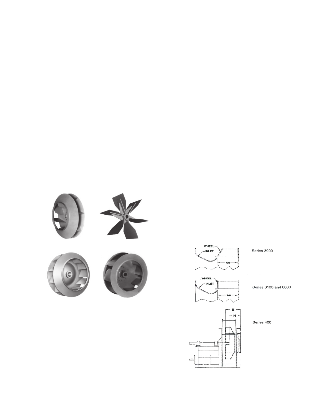
E. Fan Wheels and Fan Wheel Types
All fan wheels are balanced before shipment. They
should fi t the shaft snugly. The key should fi t both the
fan hub and shaft snugly, and the set screws should be
tightened to the appropriate torque.
Rotation of the fan equipment and its corresponding fan
wheel is designated as clockwise or counter-clockwise
viewing it from the drive side. Single inlet fans are
always considered as having the backplate side (or
side opposite the inlet) the drive side (even though they
may be arranged to drive from the inlet side).
For correct performance, it is essential that a fan wheel
of corresponding rotation be assembled in a given
housing, and also that the fan wheel be rotated in the
proper direction. This can be determined from the fact
that correct rotation of a centrifugal fan wheel is always
in the direction leading from the “cut-off” (shortest radius
of the housing) around the housing scroll towards the
outlet. Rotation of a fan wheel where the blades are
carried on a spider is easily determined from the fact
that the supporting spider or arms are on the back of
the blades. The correct rotation being in a direction
away from the supporting arms or spider.
If the bearings are received separate from the fan or
if they are removed from the fan for any reason, be
sure to keep them clean and free from dirt and other
contaminants.
H. Alignment
Bearing alignment is critical even on many ball and roller
bearings designated as “self-aligning”. On all bearings,
if the dust and dirt seals are built into the bearing
housing and not part of the race or journal assembly,
alignment should center the shaft within one-half the
normal radial clearance at the edge of the housing, to
prevent excessive dust seal wear and possible shaft
scoring.
I. Locking Devices (Bearing Collars)
Most bearings have locking devices to insure against
the shaft turning inside the inner bearing race and to
limit end play. Eccentric type collars should be turned
in the direction of shaft rotation until tight prior to
tightening the set screws. Locking devices should be
tightened only after the bearings have been properly
aligned. The locking collars may be on the inside or
outside of the bearings, depending on the design of the
equipment. In all cases the collars must be both inside
or both outside, to prevent movement of the shaft. Any
replacements should be on the same side as with the
original equipment.
J. Wheel/Inlet Installation
The wheel/inlet relationship on commercial and
industrial fans is important if optimum performance is
to be obtained. The inlet should be centered within the
wheel radially. On backwardly inclined and airfoil fans
the inlet fi t distance (AA) is measured from the inner
edge of the inlet bell to the backplate of the wheel.
Radial bladed fans may not have a backplate. For ease
of installation, the inlet fi t distance is measured from the
outside plane of the inlet to either the edge of the hub
(H) or to the backplate (B) depending upon wheel type.
K. Detail of Wheel/Inlet Installation
Air Handling Wheel
Type 400A
Series 3000 Backwardly
Inclined Flat Bladed
Open Material Handling Wheel
Type 400M
Series 8100/8800 Backwardly
Inclined Airfoil Bladed
F. Erection of Heavy Duty Fans
For large heavy duty equipment, it is recommended
that the installation be supervised by an experienced
fan erection mechanic.
G. Bearings
Depending upon bearing speed required, anti-friction
bearings are either grease lubricated at the factory or
supplied with oil cups for oil lubrication. Appropriate
bearing manufacturer’s instruction for mounting
and maintenance of the bearings are supplied in the
instruction envelope for the bearings used.
3
Page 4

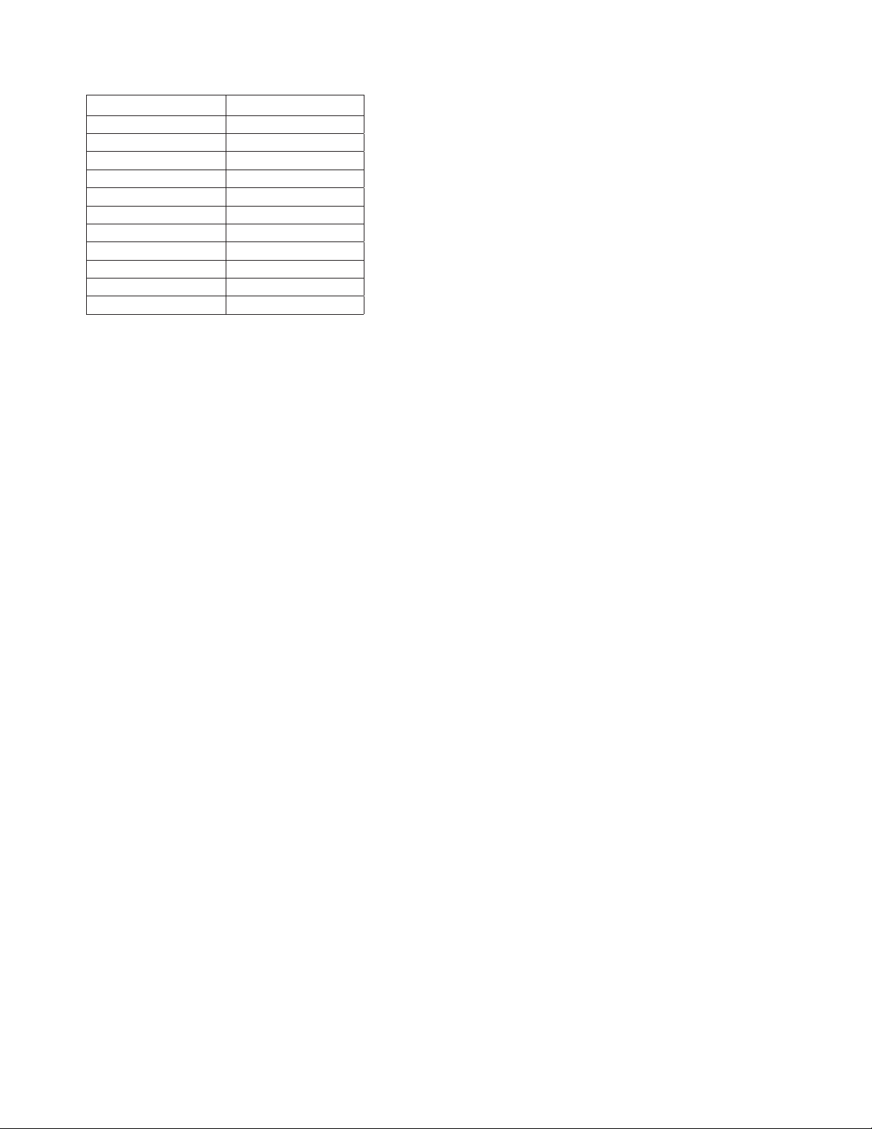
Series 3000 (AA)
Size in. mm Size in. mm
12 4.40 111.8 27 9.34 237.2
13 4.75 120.7 30 10.31 261.9
15 5.26 133.6 33 11.35 288.3
16 5.77 146.6 37 12.51 317.8
18 6.34 161.0 40 13.89 352.8
20 6.94 176.3 45 15.36 390.1
22 7.75 196.9 49 16.89 429.0
24 8.47 215.1 54 18.59 472.2
Note: Inlet clearances apply to SW fans
Series 8100 and 8800 (AA)
Size in. mm Size in. mm
18 6.34 161.0 33 11.50 292.1
20 6.97 177.0 37 12.54 318.5
22 7.68 195.1 40 13.82 351.0
24 8.54 216.9 45 15.25 387.4
27 9.42 239.3 49 17.06 433.3
30 10.46 265.7 54 18.45 468.6
Note: Inlet clearances apply to SW fans except for Series 8800
Series 400
Wheel Type A (B)* M(H)**
Size in. mm in. mm
405 3.71 94.2 2.48 63.0
407 5.28 134.1 3.52 89.4
409 6.67 169.4 4.45 113.0
411 8.24 209.3 5.49 139.4
413 9.75 247.7 6.50 165.1
415 11.25 285.8 7.50 190.5
417 12.76 324.1 8.51 216.2
419 14.21 360.9 9.47 240.5
421 15.72 399.3 10.48 266.2
423 17.23 437.6 11.49 291.8
426 19.44 493.8 12.96 329.2
429 21.75 552.5 14.50 368.3
433 24.76 628.9 16.51 419.4
437 27.72 704.1 18.48 469.4
441 30.67 779.0 20.46 519.7
445 33.69 855.7 22.47 570.7
449 36.70 932.2 24.48 621.8
* B dimension measured from the outside plane of the inlet to the
backplate.
**H dimension measured from the outside plane of the inlet to the
front edge of the hub.
L. Drives
Sheaves should be fi rmly locked in position and the key
should fi t tightly. Alignment is correct when the fan and
motor shafts are parallel and belts are perpendicular to
the shaft. A straight edge or taut cord may be used to
line up the sheaves. Belts should be under light tension
and should feel “live” when thumped. Belts should
defl ect slightly under light pressure. Excessive tension
should never be applied since it will damage the cords
and shorten the life of the belts. Never pry the belts
over the rim of the sheave, but slack off on the take-up
bolts until the belts can be slipped over the rim of the
sheaves. Prying the belts over the rim of the sheave
may break the cords and shorten the life of the belts
and may possibly damage the fan.
M. Fan Pre-Operating Checklist
Without exception, Acme recommends that all
fans include applicable guards and safety devices.
Equipment ordered without the applicable safety
devices is clearly the responsibility of the purchaser. Further, the purchaser warrants that he has determined and acquired any and all safety devices
required for equipment sold by Acme.
Before putting the fan into operation, remove any
shipping wire or blocking holding the wheel and turn it
by hand to be sure it is free and not rubbing against the
casing or inlet. Check for tightness of the wheel on the
shaft. Be sure bearings are lubricated and in alignment.
Check tightness of bearing collars as they may loosen
during shipment. Check coupling, belts or applicable
drive for alignment. Apply power momentarily to assure
correct rotation.
Factory mounted motors on fans may shift during
shipment requiring check of V-belt alignment and
tension. Re-position the motor for proper alignment
and belt tension if necessary. For centrifugal fans
re-position the motor on its base to take care of belt
tension.
Check wheel rotation when starting the unit to be sure
it conforms to the direction of the rotation arrow on the
casing.
Check bearing hold-down bolts, bearing set screws
and sleeve adaptors for tightness. Be sure to check
the bearing for lubrication. See the included bearing
instruction book for details.
SET SCREW TIGHTENING SCHEDULE
1. Before initial operation of the fan, tighten set screws
according to the procedure outlined below.
2. After 500 operating hours or three months, whichever
comes fi rst, tighten set screws to the full recommended
torque.
3. At least once a year, tighten set screws to the full
recommended torque.
PROCEDURE FOR TIGHTENING SET SCREWS IN
BEARINGS AND HUBS
One Set Screw Application
Using a torque wrench, tighten the set screw to the torque
recommended in table shown on page 5.
Two Set Screw Application
1. Using a torque wrench, tighten one set screw to half of
the torque recommended in the table shown on page 5.
2. Tighten the second set screw to the full recommended
torque.
3. Tighten the fi rst set screw to the full recommended
torque.
The operation of the vane control should be checked
before the fan is started to make sure that all links are
free, that the operation is smooth, and that there is no
distortion of the casing to cause any binding. See the
vane control installation manual for details.
4
Page 5
Recommended Tightening Torque
for Set Screws
Set Screw Diameter Torque (in-lbs)
#10 35
1/4 80
5/16 126
3/8 240
7/16 384
1/2 744
9/16 1080
5/8 1500
3/4 2580
7/8 3600
1 5400
V. INSTALLATION CHECKLIST
A. Comply with all Federal, State and local codes and
regulations.
B. Always utilize trained and experienced personnel.
C. Always use safe and inspected tools and equipment.
D. All drive and inlet/outlet guards are installed properly.
E. Fan accessories and motor are properly wired and fan is
isolated from causing a shock.
F. Location for fan is completed and ready to accept fan upon
arrival.
G. Cranes, tools and equipment needed for installation are
available.
H. Properly trained personnel are available and prepared to
handle fan.
I. Locate identifying paperwork such as Packing List and Bill of
Lading.
J. Compare paperwork with items being received for proper
items and quantity.
K. Inspect fan for damage such as dents, scrapes, bent shafts,
broken parts, etc. Inspect carefully if signs of abuse during
transit are obvious.
L. Notify carrier in writing of any problems immediately.
M. Notify Acme of any discrepancies or damage and what has
been done to correct it.
N. Read nameplate and identify fan and jobsite location.
Compare with jobsite paperwork.
O. Verify all parts are present, properly assembled and in
working order.
P. Verify proper discharge and rotation.
Q. If fan is assembled, verify that the wheel and shaft turn freely
without noise and appear to be balanced.
R. Verify that bearings have been lubricated. Verify that coupling,
if supplied, is lubricated.
S. Verify nameplate data once again. Be sure the correct fan is
on the correct application.
T. Housing Interfaces
1. Verify all tie-down bolts are tight. Verify motor is tied
down and adjusted.
2. Verify access doors, drains and other accessories are
attached and connected properly.
3. Verify all guards and safety items are in place and
adjusted.
4. Verify all ductwork is in place and is not resting on the
fan.
U. Wheel
1. Verify that the wheel is the correct rotation and in
accordance with specifi cations.
2. Verify wheel is free to turn. Adjust if necessary. Check for
inlet spacing around the wheel.
3. Check set screws in hub for tightness to shaft. Check
wheel for looseness.
4. Check key for tightness.
V. Shaft/Bearings
1. Verify shaft appears straight and key is in both ends.
2. Verify bearings are lubricated, set screws or locking
collars are tight. Check bearing mounting bolts for
tightness.
3. Verify seals and/or cooling wheels are adjusted and
properly assembled.
4. Verify fan is aligned properly.
W. V-Belt Drives
1. Verify fan sheave is on fan and motor sheave on motor
and are not switched. Set screws are tight.
2. Verify fan and motor sheaves parallel.
3. Verify fan and motor sheaves aligned and adjusted to
proper diameters if variable speed.
4. Verify belts tensioned according to specifi cations. All belts
loaded equally and matched.
5. Verify all guards are in place and adjusted.
X. Accessories
1. Verify all dampers or other controls are in working order.
2. Verify motor is wired to correct voltage. “Bump” to verify
rotation is correct.
3. Make sure all tools, personnel and debris are removed
from fan/system.
VI. START-UP OPERATION CHECKLIST
Before putting any fan into initial operation the above instructions
must be followed. In addition, the following check list must be
completed.
A. Lock out the primary and all secondary power sources.
B. A complete inspection shall be made of all of the ductwork
and the interior of the fan. Make certain there is no foreign
material which can be drawn into or blown through the fan
or ductwork. Eyes should be protected against undetected
foreign material through the use of safety goggles or other
appropriate means.
C. Make sure the foundation or mounting arrangement and the
duct connections are adequately designed in accordance
with the recognized acceptable engineering practices and
with Acme’s recommendations.
D. Check and tighten all hold-down (securing) bolts.
5
Page 6

E. Check the fan assembly and bearings for proper grounding to
prevent static electricity discharge.
F. Spin the impeller to determine whether it rotates freely and is
not grossly out of balance.
G. Inspect impeller for proper rotation for the fan design.
H. Check all set screws and tighten.
I. Check belt drive or coupling alignment; use recommended
belt tension.
J. Check the belt drive for proper sheave selection and make
sure they are not reversed (excessive speeds could develop).
K. Properly secure all safety guards.
L. Secure all access doors to the fan and ductwork.
M. Momentarily energize the fan to check the direction of
rotation.
N. Switch on the electrical supply and allow the fan to reach full
speed. Check carefully for:
1. Excessive vibration
2. Unusual noise
3. Proper belt alignment
4. Proper lubrication
5. Proper amperage and voltage values
If any problem is indicated, SWITCH OFF IMMEDIATELY. Lock
out the electrical supply, secure the fan impeller if there is a
potential for windmilling (impeller turning due to a draft through the
system). Check carefully for the cause of the trouble and correct
as necessary.
Even if the fan appears to be operating satisfactorily, shut down
after a brief period and re-check items 1 through 5 below as the
initial start up may have loosened the bolts and set screws.
The fan may now be put into operation, but during the fi rst eight
hours of running it should be periodically observed and checked for
excessive vibration and noise. At this time, checks should also be
made of motor input current and motor and bearing temperatures
to ensure that they do not exceed Acme’s recommendations or
the motor/bearing manufacturer’s recommendations.
After eight hours of satisfactory operation, the fan should be shut
down to check the following items and adjust, if necessary (lockout power and prevent windmilling).
1. All set screws and hold-down bolts
2. Drive coupling alignment
3. Belt drive alignment
4. Bearing housing temperature
5. Belt drive tension
After twenty-four hours of satisfactory operation the fan should be
shut down (power locked out) and the drive belt tension should be
re-adjusted to recommended tension.
Record fan nameplate information below for permanent records:
Size:
Fan Designation:
Max. RPM:
Max. Temp:
Serial #:
VII. GENERAL OPERATION AND MAINTENANCE
For the 3000 & 8100 models with hurricane construction that complies with
Florida Building Code including High Velocity Hurricane Zones (HVHZ) see
the ADDITIONAL INSTALLATION AND MAINTENANCE INSTRUCTIONS
on page 8.
The fans are balanced at the factory before shipping. The vibration
level of the fan installed on site is not the responsibility of ACME
unless specifi ed in the purchase contract.
ACME requires that the fans are operated within safe limits of
vibration (see the table).
Due to the transport, installation, and seismic environment of
the fan the vibration levels may change after fan installation.
Therefore, the test run with measurement of vibration levels for all
new commissioned fans is required. This step will also establish a
baseline for future predictive maintenance. It is common case that
the fans require trim balancing to achieve the vibration at or below
the start-up level (see the table).
Periodic vibration measurements are required for fans in operation
During operation of the fan, the vibration level will increase with
time due to wear and other accumulated effects. The increase of
vibration level is reasonable and safe as long as the level does not
reach alarm levels.
If the vibration increases to the alarm level, action should be taken
to determine the cause. Operation of the fan at this condition
should be carefully monitored and steps for eliminating the cause
of the increased vibration should be developed within a limited
time.
If the vibration level increases to the shut-down level the fan should
be taken out of operation. Failure to reduce the vibration over the
shut-down level could lead to bearing failure, development of
cracks in fan structure, or ultimately a catastrophic failure of the
fan.
Furthermore, fans should be checked for vibration levels if the
fan sheave, bearings(s), and/or wheel were removed from the fan
shaft or the fan was moved from its installation position.
These requirements are in accordance with ANSI/AMCA204
Standard “Balance Quality and Vibration Levels for Fans” where
details on the subject can be found.
Vibration Limits for Measurements Conducted on-Site
Values shown are peak velocities of in/sec.
vibration analyzer fi lter-out
Condition Fan rigidly mounted Fan fl exibly mounted
Start-up 0.25 in./s 0.35 in./s
Alarm 0.40 in./s 0.65 in./s
Shut-down 0.50 in./s 0.70 in./s
The vibration measurement has to be made
on the housings of the fan bearings
It is advisable to keep a record of vibration measurements in any
case but the record is required for warranty claims.
Maintenance should always be performed by experienced
and trained personnel. Do not attempt any maintenance of a fan
unless the electrical supply has been locked out or tagged out and
the impeller has been secured.
Fan wheels having badly worn blades should be replaced or
rebuilt. Rebuilt or repaired (including hard metal surfacing) fan
wheels require careful balancing before being returned to service.
Experienced personnel can give the wheel a running balance
operating on its own shaft and bearings.
Standard fans handling corrosive fumes should have the internal
parts wire brushed, scraped clean and then painted with an
corrosion-resisting paint. This process should be repeated when
the paint fi lm begins to show signs of deterioration.
6
Page 7

When a V-belt must be replaced, replace the entire set of belts as
new belts will not work properly in conjunction with used belts, due
to the difference in length.
Good fan maintenance consists of systematic and regular
inspection, testing, care and adjustment, together with the repair
or replacement of worn parts before failure occurs. Experience
will best determine the frequency of the various maintenance
operations, since the requirements will vary widely, depending
upon the severity of the application and local conditions. However,
once a schedule of maintenance operations has been set up, it
should be carefully adhered to for best results.
The successful operation of a fan depends to a large extent on
the reliable operation of the bearings and the balance of the fan
wheel.
A. Bearings
Bearings require maintenance and attention whether
in storage or operating. All assembled fan bearings are
pre-lubricated at the factory according to the bearing
manufacturer’s instructions. All bearings should be inspected
prior to start-up to insure the fan turns freely. Check the
bearings after a short interval of operation, to be certain they
are not overheated. Retighten bearing set screws after 300
hours of fan operation.
Split pillow block ball or roller bearings are lubricated at the
factory to the bearing manufacturer’s instructions. However,
if fans are to be stored in a damp, dusty and/or corrosive
atmosphere the bearings should be fi lled completely with
grease to keep contaminants out of the bearing cavity. Before
start-up be sure the bearings are cleaned and re-lubricated
following the instructions of the bearing manufacturer. Oil
lube bearings are lubricated at the factory. Before use, clean
the bearings with oil and lubricate according to the bearing
manufacturer’s instructions.
Bearing manufacturer’s instructions are provided with each
assembled fan in the instruction envelope attached to the
fan.
Motors should be lubricated in accordance with the
manufacturer’s instructions.
B. Vibration Causes
All wheels are statically and dynamically balanced at the
factory and alignment is checked. If vibration is noticed,
check the following:
1. Bearing and drive alignment
2. Shaft straightness
3. Wheel or sheave loose on shaft
4. Loose or worn bearings
5. Loose mounting bolts
6. Motor out of balance
7. Sheaves out of balance
8. Worn or corroded wheel
9. Accumulation of material on wheel
10. System design problems - One frequent system problem
is too high of a static pressure for the fan ordered. In
other words, the actual system pressure turns out to
be higher than the pressure assumed at the time the
fan was ordered. This leads to the fan operating in the
stall region, which can cause excessive vibration and
eventual failure of the fan.
WARNING! Care must be taken when cleaning the wheel to
remove grease and other foreign particles. Damage to the
wheel can occur if it is hit or if pressure is applied causing
the wheel to be distorted. Either case can cause serious
vibration and damage to the fan.
In the case of accumulated paint spray, the wheel may be
removed and cleaned in accordance with the paint manufacturer’s
instructions for both the coating applied and the underlying metal.
C. Renewal Parts
When continuous fan operation is vital, it is recommended that
spare parts such as bearings, V-belts, and in some cases, wheels
be kept on hand for emergencies.
Renewal parts should be ordered from the local sales offi ce.
All nameplate data should be provided, such as fan type, size,
style and serial number. Describe the part accurately and if the
equipment appears to be special, or if there is any doubt as to the
description, include a dimensional sketch of the part required.
7
Page 8
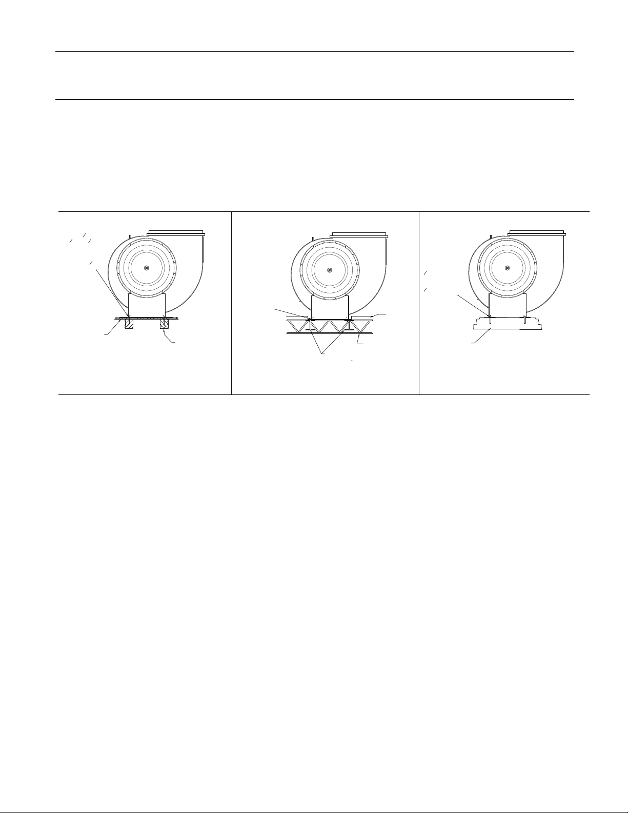
ADDITIONAL INSTALLATION AND MAINTENANCE INSTRUCTIONS
Wood Deck Installation
Metal Building Installation
Concrete Deck Installation
for the 3000 & 8100 models with hurricane construction that complies with Florida Building Code
including High Velocity Hurricane Zones (HVHZ)
This product has been issued by Miami-Dade County, Florida
an NOA No. 11-1117.04 with expiration date of February 21,
2018. The full document can be found on Miami-Dade County,
Florida website www.miamidade.gov/building. This product
is marked on its label by a statement “Miami-Dade County
Product Control Approved”.
This product shall be available for inspection at the job site at
the request of the Building Offi cial.
1
#14 x 2
Wood Screws
2
1
1
" x 2
4
5/8" plywood
roof decking
Elevation View
" Lag Bolts
2
1
"
2
4 x Southern
Yellow Pine
framing minimum
#14 Self-drilling
Screws through
roof deck, full
penetration
of threads through
truss or steel support
structure
Elevation View
or
through plywood
and into 4 x
framing with a
minimum 1
embedment.
This product may be installed on a wooden, metal or concrete
deck following the requirements shown in Figure 1. It is the
installers responsibility to follow the installation instructions
including a check that all fasteners in the outer shell of the
product have been checked and tightened.
Hilti Kwik Bolt 3
expansion anchors
3
(
" x 4" )
8
into concrete
with a minimum
1
3
" embedment
2
Minimum 20 gage
Roof Deck
Steel Roof Truss
1
8
" steel
Minimum 12 gage
Support Structure by others
Minimum
Minimum Concrete
Strength 2000PSI
Elevation View
Figure 1 - Installation of the 3000 & 8100 models with hurricane construction that complies with Florida Building Code
including High Velocity Hurricane Zones (HVHZ) on a wooden, metal or concrete deck
8
Page 9

This page intentionally left blank.
Page 10
TERMS AND CONDITIONS OF SALE
ACCEPTANCE All orders and sales are subject to
written approval and acceptance by an executive offi
cer of Acme Engineering & Manufacturing Corporation
at Muskogee, Oklahoma, (the "Company") and are not
binding on the Company until so approved.
DELIVERY All shipping and delivery dates are esti
mated only. No delays in delivery will subject the
Company to any costs, damages or fees for late deliv
ery. Delivery of the products herein specified shall be
made F.O.B. point of shipment, unless otherwise
stated. The Company shall not be liable for delay due
to causes beyond its reasonable control, such as Acts
of God, acts of the purchaser, acts of civil or military
authorities, priorities, fires, strikes, floods, epidemics,
war, riots, delays in transportation, car shortages, and
inability, due to reasons beyond its reasonable control,
to obtain necessary labor, material, or manufacturing
facilities. In the event of such a delay, the date of deliv
ery shall be extended for a period equal to the time lost
by reason of the delay.
TERMS OF PAYMENT If, in the judgment of the Com
pany, the financial condition of the purchaser at any
time does not justify continuation of manufacture or
shipment on the terms of payment specified, the Com
pany may require full or partial payment in advance.
Pro rata payments shall become due as shipments are
made. Each shipment or delivery shall constitute a
separate sale, and the default of any shipment or deliv
ery shall constitute a separate sale, and the default of
any shipment or delivery shall not vitiate the contract
as to other shipments or deliveries.
SALES AND SIMILAR TAXES The Company’s prices
do not include sales, use, excise, or similar taxes.
Consequently, in addition to the price specified herein,
the amount of any present or future sales, use, excise,
or other similar tax applicable to the sale of the product
herein shall be paid by the Purchaser, or in lieu thereof
WARNING Acme products are designed and manufactured to provide reliable performance but they are not guaranteed to be 100% free of defects. Even reliable products will
experience occasional failures and this possibility should be recognized by the Purchaser and all End Users. If these products are used in a life support ventilation system
where failure could result in loss or injury, the Purchaser and all End Users should provide adequate back-up ventilation, supplementary natural ventilation or failure alarm sys
tem, or acknowledge willingness to accept the risk of such loss or injury.
WARNING DO NOT use in HAZARDOUS ENVIRONMENTS where fan’s electrical system could provide ignition to combustible or flammable materials unless unit is specifi
cally built for hazardous environments. Comply with all local and national safety codes including the National Electrical Code (NEC) and National Fire Protection Act (NFPA).
CAUTION Guards must be installed when fan is within reach of personnel or within eight (8) feet (2.5 m) of working level or when deemed advisable for safety.
DISCLAIMER The Company has made a diligent effort to illustrate and describe the products accurately in all Company literature; however such illustrations and descriptions
are for the sole purpose of identification and do not express or imply any warranty.
the Purchaser shall provide the Company with a tax
-
exemption certificate acceptable to the taxing authori
ties.
CANCELLATION Any contract resulting from the Pur
chaser’s order may be canceled by the Purchaser only
-
by negotiations and upon payments of reasonable can
cellation charges which will take into account expenses
-
already incurred and commitments made by the Com
pany.
DESIGN CHANGES The Company reserves the right
to make changes in design, improvements and addi
tions in and to its products any time without imposing
any liability or obligations to itself to apply or install the
same in any product manufactured by it.
TITLE The title and right of possession of the products
sold herein shall remain with the Company and such
products shall remain personal property until all
payments herein (including deferred payments whether
evidenced by notes or otherwise) shall have been
made in full in cash and the Purchaser agrees to do all
acts necessary to perfect and maintain such right and
title in the Company.
PRICE ADJUSTMENTS Prices are subject to change
upon notice by the Company. Prices on existing or
ders are subject to surcharges in the event of cost in
creases of metals and transportation. All complete
component accessory material manufactured by others
and furnished with the Company’s products such as
motors, drives, vibration equipment, controls or other
completely assembled component structures, are sub
ject to adjustment to the price at time of shipment re
gardless of the date of original order entry.
SAFETY ACCESSORIES The Company manufactures
products designed to serve multiple applications and
offers a wide range of safety equipment, including
guards and other devices, as may be required to meet
customer specifications. Without exception, the Com
pany recommends that all orders include applicable
safety devices. Products ordered without applicable
safety devices is clearly the responsibility of the Pur
chaser. Further, the Purchaser warrants that it has de
termined and acquired any and all safety devices re
quired for products sold by the Company. Weather
covers and guards for motor and V-belt drives, cou
plings, shafts and bearings, along with inlet and outlet
screens, are optional accessories noted in the price
list.
GOVERNING LAW The rights, obligations and reme
dies of Purchaser and the Company, the interpretation
of these terms and conditions and the sale of products
by the Company shall be governed by Oklahoma law,
without regard to any principles of conflict of laws.
ARBITRATION Any dispute arising under or in con
nection with these terms and conditions or the sale of
products shall be settled by binding arbitration admin
istered by the American Arbitration Association under
its Commercial Arbitration Rules, and judgment on the
award rendered by the arbitrator may be entered in
any court having jurisdiction thereof. The dispute shall
-
be resolved by one neutral arbitrator who shall have no
-
affiliation with either Purchaser or the Company and
shall be selected by the American Arbitration Associa
tion office in Dallas, Texas. The arbitration proceed
ings shall be held in Muskogee, Oklahoma.
APPLICABLE DOCUMENTS The agreement be
tween the Company and the Purchaser relating to the
products includes these terms and conditions of sale,
any applicable installation and maintenance instruc
tions provided by the Company and any terms appear
ing on the Company’s quotation, sales order acknowl
edgment and invoice.
LIMITED WARRANTY
WARRANTY AND DISCLAIMER: the Company ex-
tends this limited warranty to the original purchaser
and warrants that products supplied by the Company,
shall be free from original defects in workmanship and
materials for two years from date of shipment (except
for the warranty periods noted for products listed be
low), provided same have been properly handled,
stored, installed, serviced, maintained and operated.
This warranty shall not apply to products which have
been altered or repaired without the Company’s ex
press authorization, or altered or repaired in any way
so as, in the Company’s judgment, to affect its perfor
mance or reliability, nor which have been improperly
installed or subjected to misuse, negligence, or acci
dent, or incorrectly used in combination with other sub
stances. The Purchaser assumes all risks and liability
for results of use of all products.
Evaporative cooling pads are warranted to be free of
defects in materials and workmanship for a period of
two years from date of shipment provided same have
been properly handled, stored, installed, serviced,
maintained and operated; and further, not subjected to
excessive heat, corrosive agents or chemicals, or me
chanical abuse that may cause tearing, crushing or un
due deterioration, nor used on a system or in a manner
other than that for which it was designed as explained
in the product literature.
The following products are warranted to be free of de
fects in materials and workmanship for the periods
shown from date of shipment: Acme’s exclusive du
plex split pillow block bearings and shaft five years,
belts one year, Polyethylene tubing 90 days, AIR40
Heater warranty one year, AIR40 Emitter warranty
three years and DDP fan lifetime warranty on its pro
peller, cone, and housing.
LIMITATION OF REMEDY AND DAMAGES: All
claims under this warranty must be made in writing and
delivered to P. O. Box 978, Muskogee, Oklahoma,
74402, within 15 days after discovery of the defect and
prior to the expiration of two years from the date of
shipment by the Company of the product claimed de
fective, and Purchaser shall be barred from any
ACME ENGINEERING AND
MANUFACTURING CORPORATION
P.O. Box 978
Muskogee, Oklahoma 74402
Telephone 918/682-7791
Fax 918/682-0134
www.acmefan.com
Member Air Movement and Control Association International, Inc. October 2013 690001
remedy if Purchaser fails to make such claim within
such period.
Within 30 days after receipt of a timely claim, the Company shall have the option either to inspect the product
while in Purchaser's possession or to request Pur
chaser to return the product to the Company at Pur
chaser's expense for inspection by the Company. The
Company shall replace, or at its option repair, free of
charge, any product it determines to be defective, and
it shall ship the repaired or replacement product to
Purchaser F.O.B. point of shipment; provided, how
ever, if circumstances are such as in the Company’s
judgment to prohibit repair or replacement to remedy
the warranted defects, the Purchaser's sole and exclu
sive remedy shall be a refund to the Purchaser of any
part of the invoice price, paid to the Company, for the
defective product or part.
The Company is not responsible for the cost of re
moval of the defective product or part, damages due to
removal, or any expenses incurred in shipping the
product or part to or from the Company’s plant, or the
installation of the repaired or replaced product or part.
-
The warranties set forth above do not apply to any
components, accessories, parts or attachments manu
factured by other manufacturers; such being subject to
the manufacturer’s warranty, if any. To the extent not
prohibited by the manufacturer’s warranty, the Com
pany shall pass through to Purchaser such manufac
turer’s warranty.
THE COMPANY’S WARRANTY IS IN LIEU OF ALL
OTHER WARRANTIES, EXPRESS OR IMPLIED,
ARISING BY LAW OR OTHERWISE, INCLUDING
WITHOUT LIMITATION THE IMPLIED WARRANTIES
OF MERCHANTABILITY AND FITNESS FOR A PAR
TICULAR PURPOSE, WHICH ARE HEREBY EX
PRESSLY DISCLAIMED AND WAIVED. THIS WAR
RANTY CONSTITUTES THE COMPANY’S SOLE
AND EXCLUSIVE WARRANTY FOR DEFECTIVE
GOODS AND PURCHASER’S SOLE AND EXCLU
SIVE REMEDY FOR DEFECTIVE PRODUCTS.
-
No employee, agent, dealer, or other person is
authorized to give any warranties on behalf of the
Company or to assume for the Company any
other liability in connection with any of its products
except in writing and signed by an officer of the
Company.
REPLACEMENT PARTS If replacement parts are
ordered, purchaser warrants that the original com
ponents in which these replacement parts will be
placed are in satisfactory working condition, and
when said replacement parts are installed, the resultant installation will operate in a safe manner, at
speeds and temperatures for which the original product was purchased.
-
TECHNICAL ADVICE AND RECOMMENDATIONS,
-
DISCLAIMER: Notwithstanding any past practice or
dealings or any custom of the trade, sales shall not in
clude the furnishing of technical advice or assistance
or system design. Any such assistance shall be at the
Company’s sole option and may be subject to addi
-
tional charge.
The Company assumes no obligation or liability on ac
-
count of any recommendations, opinions or advice as
to the choice, installation or use of products. Any such
recommendations, opinions or advice are given and
shall be accepted at Purchaser's and End User's risk
and shall not constitute any warranty or guarantee of
such products or their performance.
LIMITATION OF LIABILITY The cumulative liability of
the Company to the Purchaser and any other persons
for all claims in any way relating to or arising out of the
products, including, but not limited to, any cause of ac
tion sounding in contract, tort, or strict liability, shall not
exceed the total amount of the purchase price paid for
those products which are the subject of any such
claim. This limitation of liability is intended to apply
without regard to whether other provisions of this
agreement have been breached or have proven inef
fective even if the Company has been advised of the
possibility of such claims or demands. In no event
shall the Company be liable to the Purchaser or any
other person for any loss of profits or any incidental,
special, exemplary, or consequential damages for any
claims or demands brought by the Purchaser or such
other persons.
-
INDEMNITY The Company’s maximum liability to Pur
chaser and to any end user is as set forth above. The
Company makes no warranty to anyone for any prod
ucts not manufactured by the Company and shall have
no liability for any use or installation of any products
(whether manufactured by the Company or other man
ufacturers) not specifically authorized by this sale.
Purchaser acknowledges various warnings by the
Company regarding the products and its installation
and use. If the Company incurs any claims, lawsuits,
settlements, or expenses (including attorney fees) for
any loss, injury, death or property damage including,
but not limited to, claims arising out of the Purchaser’s
-
or any end user’s installation or use of the products,
the Purchaser shall indemnify and hold the Company
harmless.
-
-
-
-
-
-
-
-
-
-
-
-
-
-
-
-
-
-
-
-
-
-
-
-
 Loading...