

Acme Electric DRIVE ISOLATION TRANSFORMERS General Product Line Information
SECTION
4
D RIVE ISOLA TION TRANSFORMERS
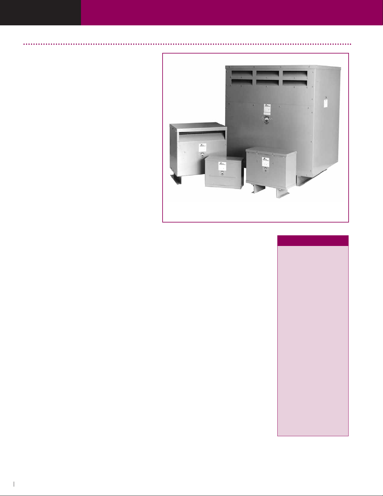
Drive Isolation Transformers
The Acme Drive Isolation Transformers are
specifically designed to accommodate the
special voltages and KV A sizes unique to AC
and DC motor drive applications.
FEA TURES
■
UL T ype 3R Enclosures with Weather Shield
on V entilated Units (above 20 KV A).Type 2
Enclosure without weather shield. UL Listed and
CSA certified. 7.5–20.0 KVA are encapsulated,
UL 3R.
■
3-Phase 60 Hertz.
■
180°C and 220°C insulation systems.
■
Encapsulated and ventilated designs. All
ventilated units, are of strip wound construction.
Acme’ s reinforced core assemblies enhance
quiet operation.
■
Nominally 6% impedance.
■
Designed for use with AC, adjustable frequency
or DC drives.
■
Full capacity taps are featured on all units. On
7.5 through 20 KV A units, taps are 1-5% ANFC
and 1-5% BNFC. On 27 through 660 KVA units,
taps are 2-2
■
Full range of KV A ratings cover all standard
drive systems.
■
Ample wiring compartment for easy cable entry.
■
Optional wall mounting brackets for certain sizes.
1
/2% ANFC and 2-21/2% BNFC.
Stress relief
Acme uses strip conductors (above 7.5 KVA) instead
of wire for a DIT series that easily accommodates
the severe electrical and mechanical stresses
found in today’ s AC & DC motor drives. The inherent
excellent line isolation of these transformers is
further enhanced with the extra protection of
Acme’ s Electrostatic Shield — free in all DIT’s.
Lower losses
The harmonic currents generated by AC & DC
drives increase eddy current losses (heat) in
transformer windings. The thicker the winding
conductor , the greater the losses. Acme uses one
turn per layer of thin strip conductor which provides
lower eddy current losses than comparable wire
wound units. Lower losses = cooler operation
and longer transformer life.
DTGB-040-4S
Reduced short
circuit forces
Strip windings minimize axial short
circuit forces that can cause mechanical
displacement of the windings under
fault conditions. For extra protection all
designs 7.5 KV A and above use primary
and secondary coils of equal axial
length. This feature tends to negate
axial short circuit forces, further
improving transformer life expectancy.
Selection
instructions
If you know the motor horse-power ,
simply follow the drive system manufacturer's recommendation. Or, select
the corresponding KV A from the chart
at right.
For example, a 40 Hp motor requires a
51 KV A DIT.
DTGA-7-2S
DTGA-014-2S
DTHA-0330-4S
H.P. KVA
5.0 7.5
7.5 11.0
10.0 14.0
15.0 20.0
20.0 27.0
25.0 34.0
30.0 40.0
40.0 51.0
50.0 63.0
60.0 75.0
75.0 93.0
100.0 118.0
125.0 145.0
150.0 175.0
200.0 220.0
250.0 275.0
300.0 330.0
400.0 440.0
500.0 550.0
600.0 660.0
54
ACME ELECTRIC, POWER DISTRIBUTION PRODUCTS DIVISION •LUMBERTON, NC •800-334-5214 •www.acmepowerdist.com
SECTION
4
D RIVE ISOLA TION TRANSFORMERS
Acme Advantages
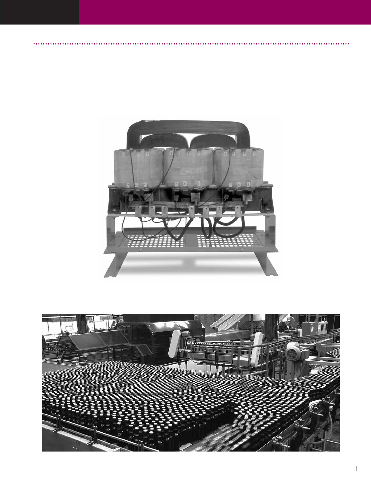
Wound Cores and Strip
Winding mean lower losses
All Acme DIT s above 7.5 KVA are wound with strip windings
to ensure the lowest possible eddy current losses. All our
DITs use a three leg wound core. This superior design has
very low losses and quiet operation. Both of these features
combine to significantly reduce losses and operating costs
compared to other types of constructions.
Copper terminations provide
trouble-free operation
All Acme DIT s up to and including 220 KVA have copper terminations. The transition from aluminum strip coil conductors
to copper terminations is accomplished by a bonding process
known as “Koldwelding
Acme for over 25 years to provide a trouble-free, permanent
bonding of the two metals.
™
”. This process has been used by
Wound core construction showing all copper terminations
ACME ELECTRIC, POWER DISTRIBUTION PRODUCTS DIVISION •LUMBERTON, NC •800-334-5214 •www.acmepowerdist.com
55
 Loading...