

INSTALLATION MANUAL
DIN Rail Power Supplies, Slimline Single Phase
SAFETY ALERT FOR YOUR SAFETY, READ ALL INSTRUCTIONS BEFORE
NOTICE: Products are not to be used nor are warranted in aerospace, nuclear, medical patient connect, or lifesafety applications.
This manual is subject to change without prior notice.
INSTALLATION AND OPERATION.
Safety Instructions WARNING – Avoid Possible Injury or Death
WARNING: Never work on the power supply when power is applied. Electric shock and arc risks can cause death, severe personal
injury or substantial property damage. Power source must be off and properly secured before any installation, maintenance or modification
work is completed. Keep away from fire and water. Before installing unit, thoroughly read these instructions.
1. As a reminder, these products are not to be installed in nuclear or medical (patient connect) applications. Units are only to be installed by
professionals. Only professionally trained personnel may open the power supply.
installation or operation of this equipment, please call the number located at the front of this document.
2. The units meet the safety requirements of UL508, UL60950-1, IEC/EN60950. They are approved in accordance with EN60950, UL508,
(TUV) EN55022, EN55024, CE MARKING and meet the requirements EMC and the Low Voltage Directive.
3. These units must always be installed with any national, county or city regulations that apply. Connections to mains supply must be in
compliance with national and city regulations. Power supply and main cables must be sufficiently fused in accordance with local codes.
Follow all applicable local and national codes that regulate the installation and operation of your equipment. These codes vary, and it is
your responsibility to determine which codes should be followed, and to verify that the equipment, installation, and operation are in
compliance with the latest revision of these codes. Equipment damage or serious injury to personnel can result by not following all
applicable standards and codes. We do not guarantee the products described in this publication are suitable for your particular
application, nor do we assume any responsibility for your product design, installation, or operation.
4. Sufficient temperature and cooling and clearances must be ensured as indicated: O
requires minimum free-space clearances on top, bottom, and sides of units to allow for airflow and heat dissipation.
5. Avoid potential danger of contact with case by ensuring all strands of stranded wire use (if applicable) are fastened in the terminal blocks.
6. SAFETY ALERT Hazardous voltages and components storing a substantial amount of energy are present in this unit during normal
operating conditions. Improper handling may result in electric shock or serious burns.
7. WARNING Do not open the power supply until at least 5 minutes after it has been disconnected from the mains on all poles.
8. Do not introduce any objects into the power supply. The output voltage adjustment potentiometer may only be actuated using
an insulated screwdriver.
If you have any questions concerning the
perating temperature requires no external cooling but
Installation Instructions WARNING – Avoid Personal Injury or Product Damage.
1. Read and follow all instructions before installation as indicated in this manual. This publication is based on information that was
available at the time it was printed. We reserve the right to make changes to the products and/or publications at any time without notice
and without obligation.
2. DIN Rail Connection; as per local electrical codes and recommended wire sizes.
3. DIN Rail mounted per VDE0160 Please see diagram as noted below.
4. This power supply is designed for professional indoor systems. During operation the power supply must not be accessible. Install and put
into service by qualified personnel only.
5. Do not operate without Protective Earth (PE) connection! To comply with EMC and safety standards (CE mark, approvals) the power
supply must be operated only if PE terminal is connected to the non-fused earth conductor.
6. Do not cover any ventilation holes. The correct mounting position for optimal cooling performance must be observed. All free space
requirements and power de-rating as specified at the beginning of this manual must be observed.
7. WARNING The internal fire safety fuse is not accessible. This fuse is not to be replaced by the user. For continued protection
against risk of fire, NO REPLACEMENT OF FUSE IS ALLOWED REGARDLESS. If this internal fuse has blown, the power supply has
a serious internal defect, and for safety reasons, must be discarded, or if under warranty, returned.
8. Please ensure that the power supply will be recycled properly at the end of its life. Some components of this power supply may be
suitable for recycling, including some that require special disposal.
A
A
INSTALLATION MANUAL
DIN Rail Power Supplies, Slimline Single Phase
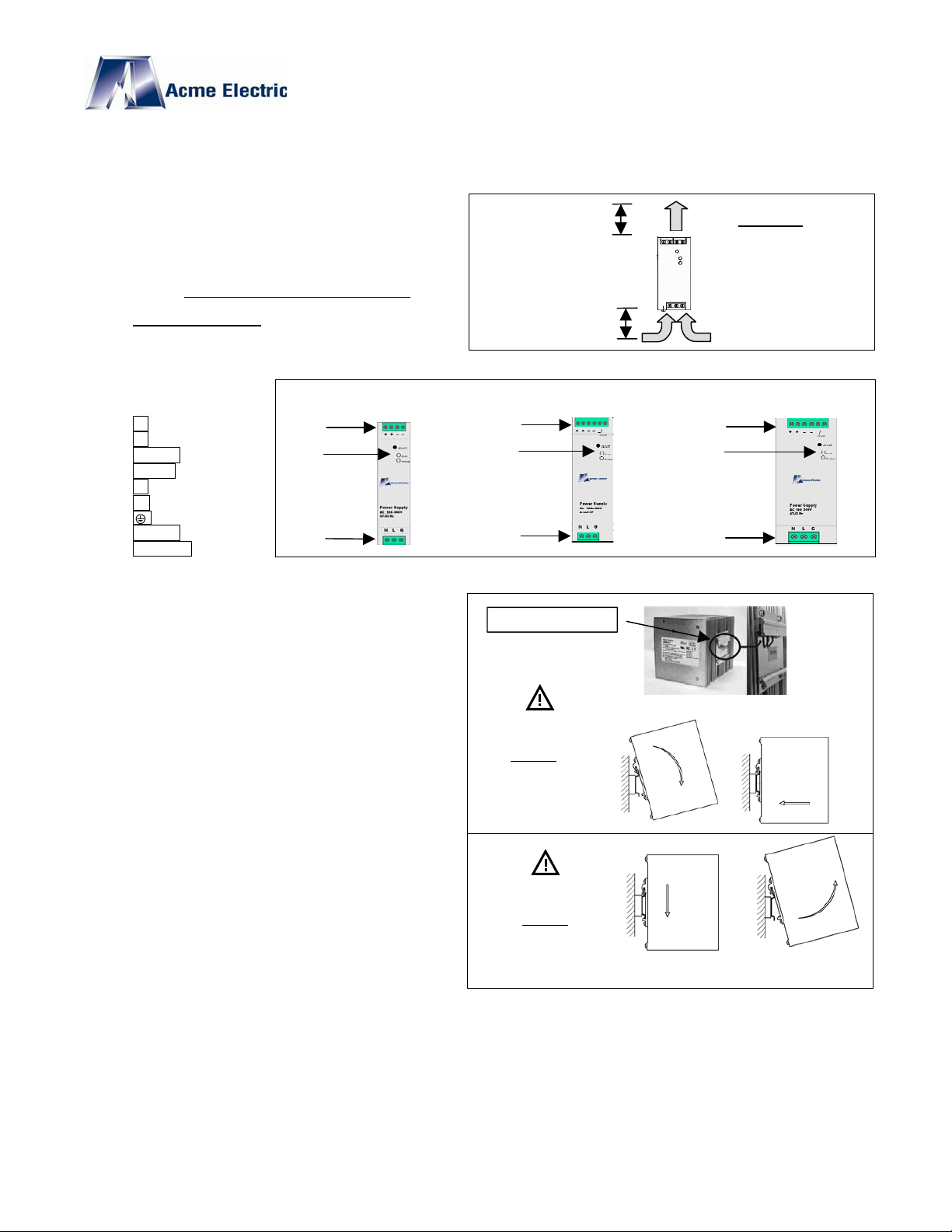
Cooling, Airflow and Free Space Clearances
1. Airflow must be as shown in figures.
2. Always maintain operation conditions within output power
and temperature ratings.
3. All units are rated for convectional cooling but require that
there is at least 25mm both above and below unit
proper airflow.
4. Do not block vent holes because by doing so it may
overheat and damage the unit.
Names and Descriptions
1. – Negative output
2. + Positive output
3. DC OK Indicator
4. Adjust DC out voltage
5. L AC mains (Line)
6. N AC mains (Neutral)
7. Safety Ground
8. DC OK output
9. Overload Indicator
1,2
4,3,9
6,5,7
80 Watt 120 Watt 240 Watt
Installation Procedure.
1. Locate mounting bracket on back of unit.
2. A spring clip is mounted to the upper channel of the
mounting bracket as shown in picture to the right.
3. Attach the Unit to the Din Rail by sliding the mounting
brackets upper channel lip and attached spring clip over
the top edge of Din Rail as shown in bottom right figure.
(The bottom of the unit should be tilted out about 10°)
4. Apply a downward pressure assuring that the top edge of
the Din Rail is firmly seated into the top channel of the
mounting bracket.
5. In the final step, swing the bottom of the unit towards the
bottom edge of the Din Rail latching the bottom of the Din
Rail to the bottom channel of the mounting bracket.
for
25 mm
25 mm
1,2,8
4,3,9
6,5,7
REAR MOUNTING CLIP
Disconnect
AC Power
Before
Installing
Wiring.
ll Models
25 mm space above
and below unit is
required for proper
airflow.
ir Flow
1,2,8
4,3,9
6,5,7
Un-Install and Removal Procedure.
1. After insuring that the AC power is disconnected from its
source, disconnect all wiring connections from Power
supply.
2. Insert pressure downward on the unit and tilt the bottom
outward, disengaging the bottom channel of the unit
bracket from the bottom edge of the Din Rail.
3. Lift the unit detaching it from the top edge of the Din Rail.
Copyright© 2008, Acme Electric Corp. Acme Electric Corp. reserves the right to make changes in the product at any time, without notification.
2008
Disconnect
AC Power
Before
Removing
Wiring.
AE Install Manual.doc 04 August
 Loading...