


8
Buck-BoostTransformers

Section
A simple and economical way to correct
offstandard voltages... from 95 to 500 volts;
single and three phase, in sizes up to 360
kVA. Simplified buck-boost rating charts make
proper transformer selection easy, accurate.
Description and Applications
Questions and Answers
Selection Charts - Single Phase
Selection Charts - Three Phase
Specifications
Wiring Diagrams
Three Phase Buck Boost
118-119
120-126
127-129
130-132
133-135
135-137
137
Buck-Boost Transformers Buck-Boost Transformers
Where are buck-boost transformers used?
A typical buck-boost application is 120 volts in, 12 volts out for low voltage lighting or control circuitry. In most applications, this low
voltage transformer is field connected as an autotransformer. (See question 2 for the definition of an autotransformer). Buck-boost
transformers provide tremendous capabilities and flexibility in kVA sizes and input/output voltage combinations. Basically you get
75 different transformers... all in one convenient package.
Other buck-boost applications are, where (A) low supply voltage exists because equipment is installed at the end of a bus system;
(B) the supply system is operating at or over its design capacity; and (C) where overall consumer demands may be so high the
utility cuts back the supply voltage to the consumer causing a “brownout.”
Why use buck-boost instead of another type transformer ?
Take a look at the advantages and disadvantages of using a buck-boost transformer (autotransformer) compared to a standard
isolation transformer of the proper size and voltage combination.
Proper voltage is critical
With nearly two-thirds of all electrical loads being A.C. motor loads, maintenance of the proper voltage to that motor is very
important. If the supply line voltage is not maintained, motor winding current is increased causing reduced motor torque and
escalating motor temperature, all of which results in the rapid loss of insulation life expectancy.
In addition to motor loads, the detrimental effects of low voltage on both resistive heating loads and incandescent lighting output
is illustrated in the chart.
Anytime you have a lower than standard voltage, equipment damage and failure can result.
Buck-boost transformers are an economical way to correct this potentially very serious problem. Anytime a line voltage change
in the 5-20% range is required, a buck-boost transformer should be considered as your first line of defense.
Advantages Disadvantages
More efficient No circuit isolation
Smaller & lighter Cannot create a neutral
5-10 times increase in kVA
Versatile, many applications
Lower cost
Application voltages and kVA
don‘t match the nameplate
voltages and kVA
118
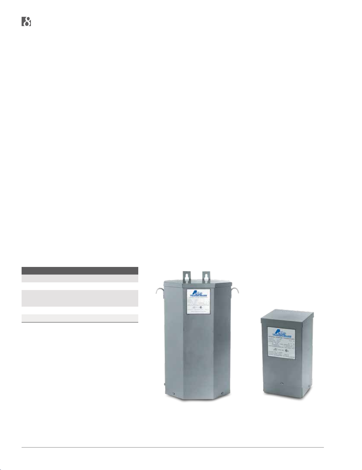
T211688
T111683
Encapsulated
Single Phase, .05 to 10.0 kVA
Features
n
UL listed, CSA certified and UL 3R enclosure, meets or exceeds all listing criteria, including NEMA, ANSI, and
OSHA standards
n
Flexibility, can be used in single phase and three pase configurations
n
Reduce (buck) or raise (boost) line voltage from 5 - 20%
n
All copper lead wire terminations
n
Long Life, 80° C rise up to 0.15 kVA, and 115° C rise above 0.25 kVA
n
Can be used in Three Phase applications
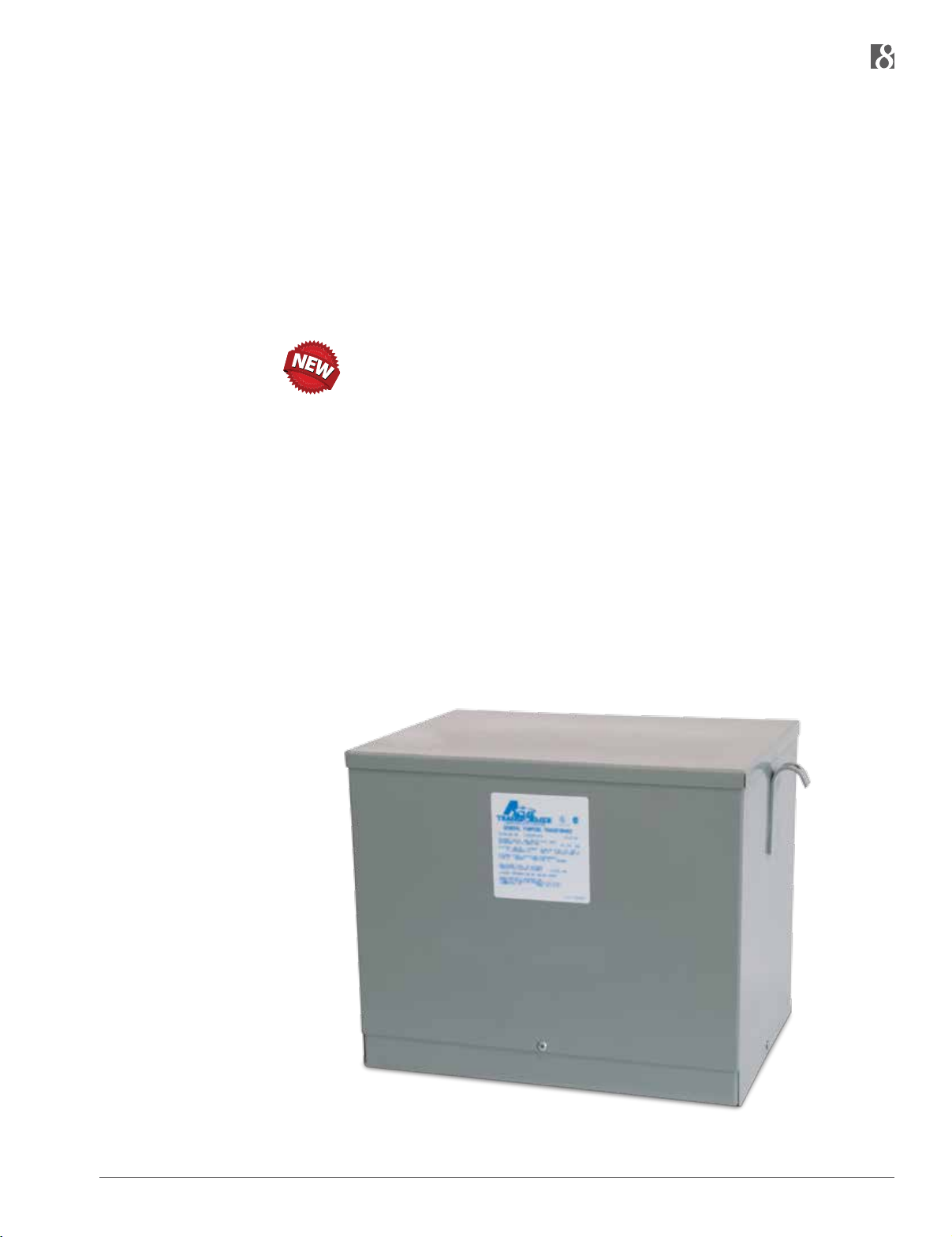
Encapsulated
Three Phase, 3.0 to 150 kVA
Features
n
UL listed, CSA certified and UL 3R enclosure, meets or exceeds all listing criteria, including NEMA, ANSI,
and OSHA standards
n
One unit, instead of multiple for 3 phase applications
n
Time and installation cost savings as units come pre-wired from the factory
n
Smaller footprint compared to using three individual single phase units
n
Long Life, UL class 180° C insulation system, 115° C rise
119
Buck-Boost Transformers Buck-Boost Transformers
Buck-Boost Transformers Buck-Boost Transformers
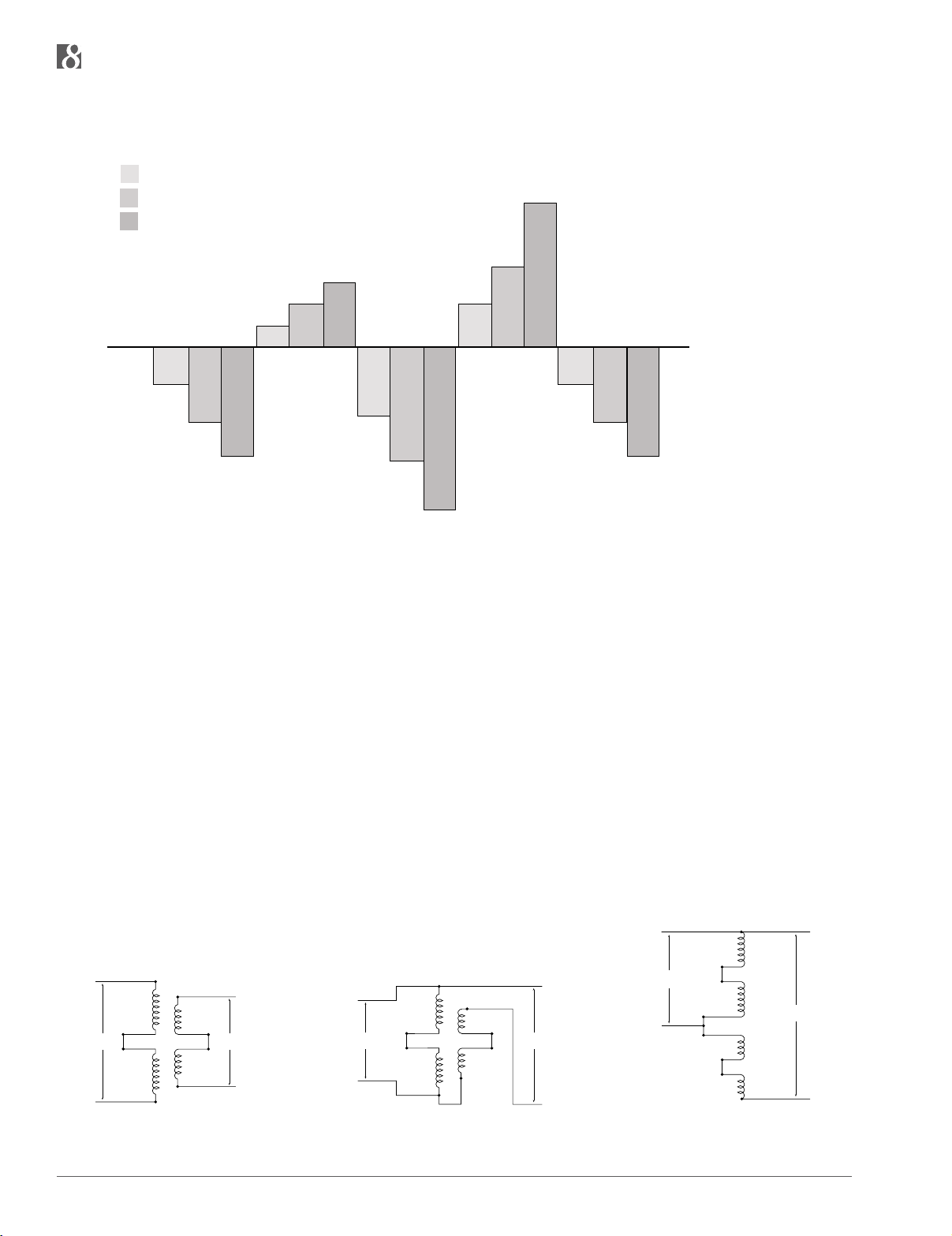
HOW LOW VOLTAGE AFFECTS VARIOUS EQUIPMENT OPERATIONS AND FUNCTIONS
150%
140%
130%
120%
110%
100%
90%
80%
70%
60%
50%
5% Low Voltage
=
10% Low Voltage
=
=
15% Low Voltage
Increase of Motor Winding
Current Requirements in
Induction Motor Loads
90.5%
81%
72%
Decrease of Heat Output in
Resistive Heating Loads
105%
111%
117%
84%
70%
Decrease of
Incandescent
Lighting Output
Increase of Motor Temperature and Corresponding
Insulation Life Expectancy
Loss
123%
111%
57%
QUESTIONS AND ANSWERS ABOUT BUCK-BOOST TRANSFORMERS
138%
90.5%
81%
Decrease in Motor Torque
Output
72%
1. What is a buck-boost transformer?
Buck-boost transformers are small single phase transformers designed to reduce (buck) or raise (boost) line voltage from 5 -20%.
The most common example is boosting 208 volts to 230 volts, usually to operate a 230 volt motor such as an air-conditioner
compressor, from a 208 volt supply line.
Buck-boosts are a standard type of single phase distribution transformers, with primary voltages of 120, 240 or 480 volts
and secondaries typically of 12, 16, 24, 32 or 48 volts. They are available in sizes ranging from 50 volt amperes to
10 kilo-volt amperes.
Buck-boost transformers are shipped ready to be connected for a number of possible voltage combinations.
2. How does a buck-boost transformer differ from an insulating transformer?
A buck-boost transformer IS an insulating type transformer when it is shipped from the factory. When it is connected at the job
site, a lead wire on the primary is connected to a lead wire on the secondary – thereby changing the transformer’s electrical
characteristics to those of an autotransformer. The primary and secondary windings are no longer “insulated” and secondary
windings are no longer “insulated” and its kVA capacity is greatly increased. Refer to figures 1, 2 and 3.
H4
H3
INPUT
H4
X1
H3
INPUT
H2
H1
Figure 1. Buck-boost transformer connected as a
low voltage insulating transformer (primary and
secondary windings shown series connected).
X2
OUTPUT
X3
X4
H4
X1
H3
INPUT
H2
H1
Figure 2. Same buck-boost transformer
connected as a boosting autotransformer. The
connection from H1 to X4 “converted” the unit to
an autotransformer.
X2
OUTPUT
X3
X4
Figure 3. Illustration No. 2 shown with the primary
and secondary windings “straightened”.
H2
H1
X4
X3
X2
X1
OUTPUT
120

3. What is the difference between a buck-boost transformer and an autotransformer?
When a primary lead wire and secondary lead wire of a buck-boost transformer are connected together electrically, in a recommended voltage bucking or boosting connection, the transformer is in all respects, an auto transformer. However, if the interconnection between the primary and secondary winding is not made, then the unit is an insulating type transformer.
APPLICATIONS
4. Why are they used?
Electrical and electronic equipment is designed to operate on standard supply voltage. When the supply voltage is constantly too
high or too low, (usually more than 55%), the equipment fails to operate at maximum efficiency. A buck and boost transformer is
a simple and ECONOMICAL means of correcting this off-standard voltage.
5. What are the most common applications for buck-boost transformers?
Boosting 208V to 230V or 240V and vice versa for commercial and industrial air conditioning systems; boosting 110V to 120V and
240V to 277V for lighting systems; voltage correction for heating systems and induction motors of all types. Many applications
exist where supply voltages are constantly above or below normal.
6. Can buck-boost transformers be used to power low voltage circuits?
Yes, low voltage control, lighting circuits, or other low voltage applications requiring either 12V, 16V, 24V, 32V or 48V. The unit is
connected as an insulating transformer and the nameplate kVA rating is the transformer’s capacity.
7. Why do buck-boost transformers have 4 windings?
To make them versatile! A four winding buck-boost transformer (2 primary and 2 secondary windings) can be connected eight
different ways to provide a multitude of voltage and kVA outputs. A two winding (1 primary & 1 secondary) buck-boost transformer
can be connected only one way.
8. Will a buck-boost transformer stabilize voltage?
No. The output voltage is a function of the input voltage. If the input voltage varies, then the output voltage will also vary by the
same percentage.
LOAD DATA
9. Are there any restrictions on the type of load that can be operated from a buck-boost transformer?
No, there are no restrictions.
10. Why can a buck-boost transformer operate a kVA load many times larger than the kVA rating on its nameplate?
Since the transformer has been auto-connected in such a fashion that the 22V secondary voltage is added to the 208V
primary voltage, it produces 230V output.
The autotransformer kVA is calculated:
kVA =
kVA =
Output Volts x Secondary Amps
1000
230 V x 41.67 Amps
1000
= 9.58 kVA
121
Buck-Boost Transformers Buck-Boost Transformers
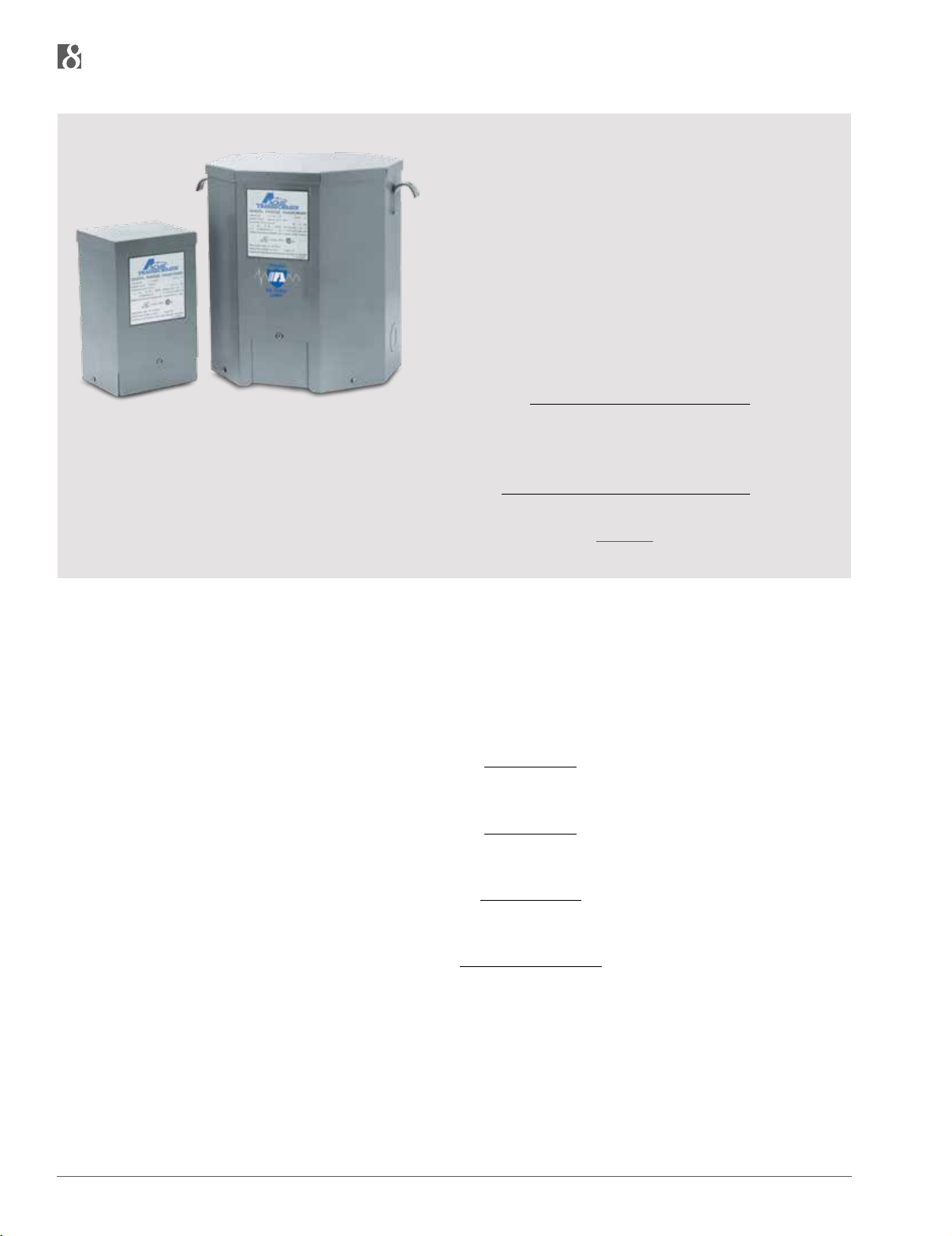
The picture to the left illustrates the difference in physical size between
the autotransformer of 1 kVA, capable of handling a 9.58 kVA load, and
an isolation transformer capable of handling a 7.5 kVA load.
To cite an example... a model T111683 buck-boost transformer has a
nameplate kVA rating of 1 kVA, but when it’s connected as an autotransformer boosting 208V to 230V, its kVA capacity increases to 9.58 kVA.
The key to understanding the operation of buck-boost transformers lies
in the fact that the secondary windings are the only parts of the transformer that do the work of transforming voltage and current. In the example above, only 22 volts are being transformed (boosted) — i.e. 208V
+ 22V = 230V. This 22V transformation is carried out by the secondary
windings which are designed to operate at a maximum current of 41.67
amps (determined by wire size of windings).
Maximum Secondary Amps =
Volts x Amps x 1.73
Secondary Volts
(1 kVA) T111683 (7.5 kVA) T2535153S
Maximum Secondary Amps =
1.0 kVA x 1000
=
24V
1000 VA = 41.67 Amps
24V
11. Can buck-boost transformers be used on motor loads?
Yes, either single or three phase. Refer to the motor data charts in Section I for determining kVA and Amps required by NEMA
standard motors.
12. How are single phase and three phase load Amps and load kVA calculated?
Single Phase Amps =
Three Phase Amps =
Single Phase kVA =
Three Phase kVA =
kVA x 1000
Volts
kVA x 1000
Volts x 1.73
Volts x Amps
1000
Volts x Amps x 1.73
1000
THREE-PHASE
13. Can buck-boost transformers be used on three-phase systems as well as single phase systems?
Yes. A single unit is used to buck or boost single phase voltage — two or three units are used to buck or boost three phase
voltage. The number of units to be used in a three - phase installation depends on the number of wires in the supply line. If the
three-phase supply is 4 wire Y, use three buck-boost transformers. If the 3 - phase supply is 3 wire Y (neutral not available),
use two buck-boost transformers. Refer to three-phase selection charts.
122

14. Should buck-boost transformers be used to develop a three-phase 4 wire Y circuit from a three-phase 3 wire
delta circuit?
No. A three phase “wye” buck-boost transformer connection should be used only on a 4 wire source of supply. A delta to wye
connection does not provide adequate current capacity to accommodate unbalanced currents flowing in the neutral wire of the 4
wire circuit.
Input (Supply System) Desired Output Connection
Delta 3 Wire WYE 3 or 4 Wire Do Not Use
Open Delta 3 Wire WYE 3 or 4 Wire Do Not Use
WYE 3 or 4 Wire Closed Delta 3 Wire Do Not Use
WYE 4 Wire WYE 3 or 4 Wire Ok
WYE 3 or 4 Wire Open Delta 3 Wire Ok
Closed Delta 3 Wire Open Delta 3 Wire Ok
3 Phase Connections
15. Why isn’t a closed delta buck-boost connection recommended?
A closed delta buck-boost auto transformer connection requires more transformer kVA than a “wye” or open delta connection and
phase shifting occurs on the output. Consequently the closed delta connection is more expensive and electrically inferior to
other three-phase connections.
CONNECTION AND FREQUENCY
16. How does the installer or user know how to connect a buck-boost transformer?
The connection chart packed with each unit shows how to make the appropriate connections. These same connection charts
are also shown in this section (page 135-136).
17. Can 60 Hertz buck-boost transformers be used on a 50 Hertz service?
No. Acme buck-boost transformers should be operated only at the frequencies recommended. However, units recommended
for 50 cycle operation are suitable for 60 cycle operation but not vice versa.
SELECTION
18. How do you select a buck-boost transformer?
Refer to the selection steps on page 126 for easy 4-step selection, then go to the charts. Also, pages 15 and 17 are helpful
for determining buck-boost kVA when only the H.P. rating of a motor is available.
NAMEPLATE DATA
19. Why are buck-boost transformers shipped from the factory as insulating transformers and not preconnected at
the factory as autotransformers?
A four winding buck-boost transformer can be auto connected eight different ways to provide a multitude of voltage and kVA
output combinations. The proper transformer connection depends on the user’s supply voltage, load voltage and load kVA.
Consequently, it is more feasible for the manufacturer to ship the unit as an insulating transformer and allow the user to
connect it on the job site in accordance with the available supply voltage and requirements of his load.
20. Why is the isolation transformer kVA rating shown on the nameplate instead of the autotransformer kVA rating?
The kVA rating of a buck-boost transformer when auto connected depends on the amount of voltage buck or boost. Since the
amount of voltage buck or boost is different for each connection, it is physically impossible to show all of the various voltage
combinations and attainable kVA ratings on the nameplate. A connection chart showing the various attainable single phase
and three-phase connections is packed with each unit.
123

Buck-Boost Transformers Buck-Boost Transformers
SAFETY
21. Do buck-boost transformers present a safety hazard usually associated with autotransformers?
No. Most autotransformers, if they are not of the buck-boost variety, change voltage from one voltage class to another. (Example
480V to 240V) In a system where one line is grounded, the user thinks he has 240V; yet due to the primary and secondary being
tied together, it is possible to have 480V to ground from the 240V output. A buck-boost transformer only changes the voltage a small
amount, such as 208V to 240V. This small increase does not represent a safety hazard, as compared to a buck of 480V to 240V.
SOUND LEVELS
22. Are buck-boost transformers as quiet as standard isolation transformers?
Yes. However, an auto-connected buck-boost transformer will be quieter than an isolation transformer capable of handling
the same load. The isolation transformer would have to be physically larger than the buck-boost transformer, and small transformers are quieter than larger ones. (Example) 1 kVA — 40 db; 75 kVA — 50 db. (db is a unit of sound measure).
COST AND LIFE EXPECTANCY
23. How does the cost of a buck-boost transformer compare to that of an insulating transformer — both capable of
handling the same load?
For the most common buck-boost applications, the dollar savings are generally greater than 75% compared to the use of an
insulating type distribution transformer for the same application.
24. What is the life expectancy of a buck boost transformer?
The life expectancy of a buck-boost transformer is the same as the life expectancy of other dry type transformers.
NATIONAL ELECTRICAL CODE
25. Your catalog indicates that a buck-boost transformer is suitable for connecting as an AUTOTRANS-FORMER.
What is the definition of an autotransformer and how does it differ from an isolation transformer?
An autotransformer is a transformer in which the primary (input) and the secondary (output) are electrically connected to
each other. An isolation transformer, also known as an insulating transformer, has complete electrical separation between the
primary (input) and the secondary (output). This is illustrated in the drawing below.
An autotransformer changes or transforms only a portion of the electrical energy it transmits. The rest of the electrical energy
flows directly through the electrical connections between the primary and secondary. An isolation transformer (insulating
transformer) changes or transforms all of the electrical energy it transmits.
Consequently, an autotransformer is smaller, lighter in weight, and less costly than a comparable kVA size insulating transformer.
Please refer to Question 27 for additional information on auto transformers.
Buck-boost transformers are frequently field-connected as auto transformers.
Diagram 450-4
PRIMARY
(INPUT)
AUTOTRANSFORMER
SECONDARY
(OUTPUT)
PRIMARY
(INPUT)
ISOLATION
TRANSFORMER
(ALSO CALLED
“INSULATING TRANSFORMER”)
SECONDARY
(OUTPUT)
A
SHUNT WINDING(S)
124
B

26. Buck-boost transformers are almost always installed as auto-transformers. Does the N.E.C. (National Electrical
Code) permit the use of autotransformers?
Yes. Please refer to N.E.C. Article 450-4, “Autotransformers 600 Volts, Nominal, or Less.” Item (a) explains how to overcurrent
protect an autotransformer; item (b) explains that an insulating transformer such as a buck-boost transformer may be field
connected as an autotransformer.
27. When a buck-boost transformer is connected as an autotransformer such as boosting 208V to 230V, the kVA is
greatly increased. What is the procedure for determining the size (ampere rating) of the overcurrent protective device
such as a fuse or circuit breaker?
The National Electrical Code Article 450-4 addresses overcurrent protection of autotransformers. A copy is reproduced below
for easy reference.
450-4. Autotransformers 600 Volts, Nominal, or Less.
(a) Overcurrent Protection. Each autotransformer 600 volts, nominal, or less shall be protected by an individual overcurrent
device installed in series with each ungrounded input conductor. Such overcurrent device shall be rated or set at not more
than 125 percent of the rated full-load input current of the autotransformer. An overcurrent device shall not be installed in
series with the shunt winding (the winding common to both the input and the output circuits) of the autotransformer between
Points A and B as shown in Diagram 450-4.
Exception: Where the rated input current of an autotransformer is 9 am peres or more and 125 percent of this current does
not correspond to a standard rating of a fuse or non-adjustable circuit breaker, the next higher standard rating described in
Section 240-6 shall be permitted. When the rated input current is less than 9 amperes, an overcurrent device rated or set at
not more than 167 percent of the input current shall be permitted.
(b) Transformer Field-Connected as an Autotransformer. A transformer field-connected as an autotransformer shall be
identified for use at elevated voltage.
28. I have noted the reprint of the N.E.C. (National Electrical Code), Article 450-4 shown in the previous question
covering autotransformer overcurrent protection. Could you explain this article in detail by citing an example?
An example of an everyday application is always a good way to explain the intent of the “Code.” Example: A 1 kVA transformer Catalog No. T111683 has a primary of 120 x 240V and a secondary of 12 x 24V. It is to be connected as an autotransformer at the time of installation to raise 208V to 230V single phase.
When this 1 kVA unit is connected as an autotransformer for this voltage combination, its kVA rating is increased to 9.58 kVA
(may also be expressed as 9,580 VA). This is the rating to be used for determining the full load input amps and the sizing of
the overcurrent protect device (fuse or breaker) on the input.
Full Load Input Amps =
9,580 Volt Amps
208 Volts
= 46 Amps
When the full load current is greater than 9 amps, the overcurrent protective device (usually a fuse or non-adjustable breaker)
amp rating can be up to 125 percent of the full load rating of the autotransformer input amps.
Max. amp rating of the overcurrent device = 46 amps x 125% = 57.5 amps
The National Electrical Code, Article 450-4 (a) Exception, permits the use of the next higher standard ampere rating of the
overcurrent device. This is shown in Article 240-6 of the N.E.C.
Max. size of the fuse or circuit breaker = 60 amps
125

Buck-Boost Transformers Selection Charts Selection Charts Buck-Boost TransformersBuck-Boost Transformers Buck-Boost Transformers
SELECTING A BUCK-BOOST TRANSFORMER
You should have the following information before selecting a buck-boost transformer.
Line Voltage — The voltage that you want to buck (decrease) or boost (increase). This can be found by measuring the supply
line voltage with a voltmeter.
Load Voltage — The voltage at which your equipment is designed to operate. This is listed on the nameplate of the load
equipment.
Load kVA or Load Amps — You do not need to know both — one or the other is sufficient for selection purposes. This information usually can be found on the nameplate of the equipment that you want to operate.
Frequency — The supply line frequency must be the same as the frequency of the equipment to be operated —
either 50 or 60 cycles.
Phase — The supply line should be the same as the equipment to be operated — either single or three phase.
Four Step Selection
1. A series of LINE VOLTAGE and LOAD VOLTAGE combinations are listed across the top of each selection chart. Select a
LINE VOLTAGE and LOAD VOLTAGE combination from ANY of the charts that comes closest to matching the LINE VOLTAGE
and LOAD VOLTAGE of your application.
2. Read down the column you have selected until you reach either the LOAD kVA or LOAD AMPS of the equipment you want
to operate. You probably will not find the exact value of LOAD kVA or LOAD AMPS so go to the next higher rating.
3. From this point, read across the column to the far left-hand side and you have found the catalog number of the exact buckboost transformer you need. Refer to the catalog number listing on page 133 and 135 for dimensions.
4. CONNECT the transformer according to the connection diagram specified at the bottom of the column where you selected
YOUR LINE VOLTAGE and LOAD VOLTAGE combination. Connection diagrams are found at the end of this section.
This same connection information is packed with each buck-boost transformer.
126

Single Phase Application Boosting Bucking
Line Voltage (Available)
Load Voltage (Output)
Catalog Number
T181047
T181048
T181049
T181050
T181051
T181052
T111683
T111684
T111685
T111686
T111687
T111688 ①
T111689 ①
See Page 135 for Connection Diagrams D D C C H H H H F F I I I E
① See chart on page 134, for number of leads per termination.
NOTE: Inputs and Outputs may be re versed; kVA capacity remains constant. All applications above bold face line are suitable for 50/60 Hz. All applications below bold face line are suitable for 60 Hz only.
With larger kVA buck-boost units, it is necessary to utilize multiple conductors on the secondary (X) terminals as shown in the chart on page 134.
Load
Load
Load
Load
Load
Load
Load
Load
Load
Load
Load
Load
Load
kVA 0.24 0.25 0.48 0.50 0.43 0.48 0.49 0.50 0.52 0.54 0.47 0.50 0.52 1.02
Amps 2.08 2.08 4.17 4.17 2.08 2.08 2.08 2.08 4.60 4.60 2.28 2.28 2.28 4.37
Maximum Size of
Fuse or Breaker
kVA 0.47 0.50 0.96 1.01 0.87 0.96 0.99 1.01 1.04 1.08 0.95 1.00 1.04 2.04
Amps 4.17 4.17 8.33 8.33 4.17 4.17 4.17 4.17 9.20 9.20 4.56 4.56 4.58 8.75
Maximum Size of
Fuse or Breaker
kVA 0.71 0.75 1.43 1.51 1.30 1.43 1.48 1.51 1.56 1.62 1.42 1.50 1.56 3.00
Amps 6.25 6.25 12.50 12.50 6.25 6.25 6.25 6.25 13.80 13.80 6.86 6.86 6.86 13.10
Maximum Size of
Fuse or Breaker
kVA 1.19 1.25 2.40 2.50 2.16 2.39 2.46 2.52 2.60 2.75 2.37 2.50 2.60 5.10
Amps 10.42 10.40 20.80 20.80 10.40 10.40 10.40 10.40 22.80 22.80 11.40 11.40 11.40 21.80
Maximum Size of
Fuse or Breaker
kVA 2.37 2.50 4.80 5.00 4.33 4.79 4.93 5.04 5.20 5.40 4.47 5.00 5.20 10.20
Amps 20.83 20.83 41.67 41.67 20.83 20.83 20.83 20.83 46.80 46.80 22.80 22.80 22.80 43.70
Maximum Size of
Fuse or Breaker
kVA 3.56 3.75 7.17 7.56 6.50 7.19 7.41 7.56 7.80 8.15 7.10 7.50 7.80 15.30
Amps 31.25 31.25 62.50 62.50 31.25 31.25 31.25 31.25 68.50 69.50 34.40 34.40 34.40 65.50
Maximum Size of
Fuse or Breaker
kVA 4.75 5.00 9.58 10.00 8.66 9.58 9.87 10.00 10.40 10.80 9.50 10.00 10.00 20.40
Amps 41.67 41.67 83.31 83.31 41.67 41.67 41.67 41.67 91.50 91.50 45.80 45.80 45.80 87.50
Maximum Size of
Fuse or Breaker
kVA 7.12 7.50 14.40 15.10 13.00 14.30 14.80 15.10 15.00 16.20 14.24 15.00 15.60 30.60
Amps 62.50 62.50 125.00 125.00 62.50 62.50 62.50 62.50 138.00 138.00
Maximum Size of
Fuse or Breaker
kVA 9.50 10.00 19.20 20.20 17.30 19.16 19.70 20.10 20.80 21.60 19.00 20.00 20.30 40.80
Amps 83.30 83.30 166.60 166.60 83.30 83.30 83.30 83.30 183.00 183.00 91.60 91.60 91.20 175.00
Maximum Size of
Fuse or Breaker
kVA 14.20 15.00 28.80 30.00 26.00 28.70 29.60 30.30 31.20 32.50 28.50 30.00 31.20 61.00
Amps 125.00 125.00 250.00 250.00 125.00 125.00 125.00 125.00 275.00 275.00 136.80 136.80 136.80 263.00
Maximum Size of
Fuse or Breaker
kVA 23.70 25.00 47.90 50.00 43.30 47.80 49.30 50.30 52.00 54.00 47.40 50.00 52.00 102.00
Amps 208.00 208.00 416.60 416.60 208.00 208.00 208.00 208.00 457.00 457.00 228.00 228.00 228.00 437.00
Maximum Size of
Fuse or Breaker
kVA 35.60 37.50 71.90 75.60 65.00 71.80 74.00 75.60 78.00 81.00 71.00 76.00 78.00 153.00
Amps 312.50 312.50 625.00 625.00 312.50 312.50 312.50 312.50 688.00 688.00 344.00 344.00 344.00 655.00
Maximum Size of
Fuse or Breaker
kVA 47.50 50.00 95.80 100.00 86.60 95.80 98.70 101.00 104.00 108.00 95.00 100.00 104.00 204.00
Amps 416.60 416.60 833.30 833.30 416.60 416.60 416.60 416.60 915.00 915.00 458.00 458.00 458.00 875.00
Maximum Size of
Fuse or Breaker
95 100 105 110 189 208 215 220 125 132 230 245 250 252
114 120 115 120 208 230 237 242 113 120 208 222 227 240
6 6 10 10 6 6 6 6 10 10 6 6 6 10
10 10 15 15 10 10 10 10 15 15 10 10 10 15
15 15 20 20 15 15 15 15 20 20 15 15 15 15
25 25 40 30 15 15 15 15 30 30 15 15 15 30
35 35 60 60 30 30 30 30 60 60 30 30 30 60
50 50 90 90 45 45 45 45 80 80 40 40 40 80
70 70 125 125 60 60 60 60 110 110 60 60 50 110
68.60 68.60 68.60 132.00
100 100 175 175 90 90 90 90 150 175 80 80 80 175
125 125 250 250 125 125 125 125 225 225 110 110 110 225
200 200 350 350 175 175 175 175 350 350 175 175 175 350
350 350 600 600 300 300 300 300 600 600 300 300 300 600
500 500 1000 1000 450 450 450 450 800 800 400 400 400 800
700 700 1200 1200 600 600 600 600 1200 1200 600 600 600 1200
127

Buck-Boost Transformers Selection Charts Selection Charts Buck-Boost Transformers
Single Phase Application Boosting Bucking
Line Voltage (Available)
Load Voltage (Output)
Catalog Number
T181054
T181055
T181056
T181057
T181058
T181059
T113073
T113074
T113075
T113076
T113077
T213078 ①
T213079 ①
See Page 135 for Connection Diagrams D C C H H G G G F I E E E E
① See chart on page 134, for number of leads per termination.
NOTE: Inputs and Outputs may be re versed; kVA capacity remains constant. All applications above bold face line are suitable for 50/60 Hz. All applications below bold face line are suitable for 60 Hz only.
With larger kVA buck-boost units, it is necessary to utilize multiple conductors on the secondary (X) terminals as shown in the chart on page 134.
Load
Load
Load
Load
Load
Load
Load
Load
Load
Load
Load
Load
Load
kVA 0.19 0.36 0.37 0.38 0.38 0.72 0.73 0.75 0.42 0.37 0.75 0.77 0.78 0.80
Amps 1.56 3.13 3.13 1.56 1.56 3.13 3.13 3.13 3.54 1.77 3.33 3.33 3.33 3.33
Maximum Size of
Fuse or Breaker
kVA 0.38 0.71 0.74 0.75 0.76 1.44 1.47 1.50 0.84 0.74 1.50 1.53 1.56 1.59
Amps 3.13 6.25 6.25 3.13 3.13 6.25 6.25 6.25 7.08 3.54 6.67 6.67 6.67 6.67
Maximum Size of
Fuse or Breaker
kVA 0.56 1.07 1.12 1.13 1.14 2.16 2.20 2.25 1.26 1.11 2.25 2.30 2.34 2.39
Amps 4.69 9.38 9.38 4.69 4.69 9.38 9.38 9.38 10.63 5.31 10.00 10.00 10.00 10.00
Maximum Size of
Fuse or Breaker
kVA 0.94 1.78 1.86 1.88 1.91 3.59 3.67 3.75 2.11 1.84 3.75 3.83 3.90 3.98
Amps 7.81 15.63 15.63 7.81 7.81 15.63 15.63 15.63 17.71 8.85 16.67 16.67 16.67 16.67
Maximum Size of
Fuse or Breaker
kVA 1.88 3.56 3.72 3.75 3.81 7.19 7.34 7.50 4.21 3.68 7.50 7.67 7.80 7.97
Amps 15.63 31.25 31.25 15.63 15.63 31.25 31.25 31.25 35.42 17.71 33.33 33.33 33.33 33.33
Maximum Size of
Fuse or Breaker
kVA 2.81 5.34 5.58 5.63 5.72 10.78 11.02 11.25 6.32 5.53 11.25 11.50 11.70 11.95
Amps 23.44 46.88 46.88 23.44 23.44 46.88 46.88 46.88 53.13 26.56 50.00 50.00 50.00 50.00
Maximum Size of
Fuse or Breaker
kVA 3.75 7.13 7.44 7.50 7.63 14.38 14.69 15.00 8.43 7.37 15.00 15.33 15.60 15.93
Amps 31.25 62.50 62.50 31.25 31.25 62.50 62.50 62.50 70.83 35.42 66.67 66.67 66.67 66.67
Maximum Size of
Fuse or Breaker
kVA 5.63 10.69 11.16 11.25 11.44 21.56 22.03 22.50 12.64 11.05 22.50 23.00 23.40 23.90
Amps 46.90 93.80 93.80 46.90 46.90 93.80 93.80 93.80 106.30 53.10
Maximum Size of
Fuse or Breaker
kVA 7.50 14.25 14.88 15.00 15.25 28.75 29.38 30.00 16.86 14.73 30.00 30.67 31.20 31.87
Amps 62.50 125.00 125.00 62.50 62.50 125.00 125.00 125.00 141.70 70.80 133.30 133.30 133.30 133.30
Maximum Size of
Fuse or Breaker
kVA 11.25 21.38 22.31 22.50 22.88 43.13 44.06 45.00 25.29 22.10 45.00 46.00 46.80 47.80
Amps 93.80 187.50 187.50 93.80 93.80 187.50 187.50 187.50 212.50 106.30 200.00 200.00 200.00 200.00
Maximum Size of
Fuse or Breaker
kVA 18.75 35.63 37.19 37.50 38.13 71.88 73.44 75.00 42.15 36.83 75.00 76.67 78.00 79.67
Amps 156.30 312.50 312.50 156.30 156.30 312.50 312.50 312.50 354.20 177.10 333.30 333.30 333.30 333.30
Maximum Size of
Fuse or Breaker
kVA 28.10 53.40 55.80 56.30 57.20 107.80 110.20 112.50 63.20 55.30 112.50 115.00 117.00 119.50
Amps 234.40 468.80 468.80 234.40 234.40 468.80 468.80 468.80 531.30 265.60 500.00 500.00 500.00 500.00
Maximum Size of
Fuse or Breaker
kVA 37.50 71.30 74.40 75.00 76.30 143.80 146.90 150.00 84.30 73.70 150.00 153.30 156.00 159.30
Amps 312.50 625.00 625.00 312.50 312.50 625.00 625.00 625.00 708.30 354.20 666.70 666.70 666.70 666.70
Maximum Size of
Fuse or Breaker
95 100 105 208 215 215 220 225
120 114 119 240 244 230 235 240
6 6 6 6 6 6 6 6 6 3 6 6 6 6
10 15 6 6 15 15 15 15
10 15 15 10 10 15 15 15 15 6 15 15 15 15
15 25 25 15 15 25 25 25 20 15 20 20 20 20
25 45 45 25 25 45 45 45 40 20 40 40 40 40
40 70 70 40 40 70 70 70 60 30 60 60 60 60
50 90 90 50 50 90 90 90 80 40 80 80 80 80
80 150 150 70 70 125 125 125 125 60 125 125 125 125
100 200 200 90 90 175 175 175 175 80 175 175 175 175
150 300 300 150 150 250 250 250 250 125 250 250 250 250
250 450 450 225 225 450 450 450 400 200 400 400 400 400
400 700 700 350 350 700 700 700 600 300 600 600 600 600
500 1000 1000 450 450 1000 1000 1000 800 400 800 800 800 800
135 240 240 245 250 255
119 208 225 230 234 239
15 6 15 15 15 15
100.00 100.00 100.00 100.00
128

Single Phase Application Boosting Bucking
Line Voltage (Available)
Load Voltage (Output)
Catalog Number
T181061
T181062
T181063
T181064
T181065
T181066
T137920
T137921
T137922
T137923
T137924
T243570①
T243571①
See Page 135 for Connection Diagrams D H H H H G G H G G J I E E
① See chart on page 134, for number of leads per termination.
NOTE: Inputs and Outputs may be re versed; kVA capacity remains constant. All applications above bold face line are suitable for 50/60 Hz. All applications below bold face line are suitable for 60 Hz only.
With larger kVA buck-boost units, it is necessary to utilize multiple conductors on the secondary (X) terminals as shown in the chart on page 134.
Load
Load
Load
Load
Load
Load
Load
Load
Load
Load
Load
Load
Load
kVA 0.29 0.44 0.48 0.49 0.49 0.95 0.96 0.50 0.98 1.01 0.29 0.50 1.05 1.10
Amps 1.04 1.04 1.04 1.04 1.04 2.08 2.08 1.04 2.08 2.08 1.25 1.15 2.29 2.29
Maximum Size of
Fuse or Breaker
kVA 0.58 0.87 0.95 0.97 0.99 1.90 1.93 1.01 1.97 2.01 0.58 1.00 2.09 2.20
Amps 2.08 2.08 2.08 2.08 2.08 4.17 4.17 2.08 4.17 4.17 2.50 2.29 4.58 4.58
Maximum Size of
Fuse or Breaker
kVA 0.87 1.31 1.43 1.46 1.48 2.86 2.89 1.51 2.95 3.02 0.86 1.50 3.14 3.30
Amps 3.13 3.13 3.13 3.13 3.13 6.25 6.25 3.13 6.25 6.25 3.75 3.44 6.88 6.88
Maximum Size of
Fuse or Breaker
kVA 1.44 2.19 2.38 2.43 2.46 4.76 4.81 2.52 4.92 5.03 1.44 2.50 5.23 5.50
Amps 5.21 5.21 5.21 5.21 5.21 5.21 10.42 5.21 10.42 10.42 6.25 5.73 11.46 11.46
Maximum Size of
Fuse or Breaker
kVA 2.89 4.38 4.76 4.86 4.93 9.52 9.62 5.04 9.83 10.06 2.88 5.00 10.45 11.00
Amps 10.42 10.42 10.42 10.42 10.42 20.83 20.83 10.42 20.83 20.83 12.50 11.46 22.92 22.92
Maximum Size of
Fuse or Breaker
kVA 4.33 6.56 7.14 7.30 7.39 14.28 14.44 7.56 14.75 15.09 4.31 7.49 15.68 16.50
Amps 15.63 15.63 15.63 15.63 15.63 31.25 31.25 15.63 31.25 31.25 18.75 17.19 34.38 34.38
Maximum Size of
Fuse or Breaker
kVA 5.77 8.57 9.52 9.73 9.85 19.04 19.25 10.08 19.67 20.13 5.75 9.99 20.90 22.00
Amps 20.83 20.83 20.83 20.83 20.83 41.67 41.67 20.83 41.67 41.67 25.00 22.92 45.83 45.83
Maximum Size of
Fuse or Breaker
kVA 8.66 13.13 14.28 14.59 14.78 28.56 28.88 15.13 29.50 30.19 8.63 14.99 31.35 33.00
Amps 31.25 31.25 31.25 31.25 31.25 62.50 62.50 31.25 62.50 62.50
Maximum Size of
Fuse or Breaker
kVA 11.54 17.50 19.04 19.46 19.71 38.08 38.50 20.17 39.33 40.25 11.50 19.98 41.80 44.00
Amps 41.67 41.67 41.67 41.67 41.67 83.33 83.33 41.67 83.33 83.33 50.00 45.83 91.67 91.67
Maximum Size of
Fuse or Breaker
kVA 17.31 26.25 28.56 29.19 29.56 57.13 57.75 30.25 59.00 60.38 17.25 29.98 62.70 66.00
Amps 62.50 62.50 62.50 62.50 62.50 125.00 125.00 62.50 125.00 125.00 75.00 68.80 137.50 137.50
Maximum Size of
Fuse or Breaker
kVA 28.90 43.80 47.60 48.60 49.30 95.20 96.20 50.40 98.30 100.60 28.80 50.00 104.50 110.00
Amps 104.20 104.20 104.20 104.20 104.20 208.30 208.30 104.20 208.30 208.30 125.00 114.60 229.20 229.20
Maximum Size of
Fuse or Breaker
kVA 43.30 65.60 71.40 73.00 73.90 142.80 144.40 75.60 147.50 150.90 43.10 74.90 156.80 165.00
Amps 156.30 156.30 156.30 156.30 156.30 312.50 312.50 156.30 312.50 312.50 187.50 171.90 343.80 343.80
Maximum Size of
Fuse or Breaker
kVA 57.70 87.50 95.20 97.30 98.50 190.40 192.50 100.80 196.70 201.30 57.50 99.90 209.00 220.00
Amps 208.30 208.30 208.30 208.30 208.30 416.70 416.70 208.30 416.70 416.70 250.00 229.20 458.30 458.30
Maximum Size of
Fuse or Breaker
230 380 416 425 430 435 440 440 450 460
277 420 457 467 473 457 462 484 472 483
3 3 3 3 3 6 6 3 6 6 3 3 6 6
6 6 6 6 6 10 10 6 10 10 6 6 10 10
10 6 6 6 6 15 15 6 15 15 6 6 15 15
15 10 10 10 10 15 15 10 15 15 10 10 15 15
20 15 15 15 15 30 30 15 30 30 15 15 30 30
25 25 25 25 25 45 45 25 45 45 20 20 45 45
35 30 30 30 30 60 60 30 60 60 30 30 60 60
50 50 45 45 45 90 90 45 90 90 40 40 90 90
70 60 60 60 60 110 110 60 110 110 60 60 110 110
100 90 90 90 90 175 175 90 175 175 80 80 175 175
175 150 150 150 150 300 300 150 300 300 150 150 300 300
250 225 225 225 225 450 450 225 450 450 200 200 450 450
350 300 300 300 300 600 600 300 600 600 300 300 600 600
277 480 480 504
230 436 456 480
37.50 34.38 68.75 68.75
129

Buck-Boost Transformers Selection Charts Selection Charts Buck-Boost Transformers
Three Phase Application Boosting Bucking
189Y
196Y
201Y
Line Voltage (Available)
Load Voltage (Output)
Catalog Number
T181047
T181048
T181049
T181050
T181051
T181052
T111683
T111684
T111685
T111686
T111687
T211688 ①
T211689 ①
Quantity Required
See Page 136 for Connection Diagrams A-A F-F F-F A-A B-B B-B B-B C-C E-E E-E E-E E-E
① See chart on page 134, for number of leads per termination.
130
Load
Load
Load
Load
Load
Load
Load
Load
Load
Load
Load
Load
Load
kVA 1.50 0.84 0.87 1.66 0.75 0.83 0.87 1.58 0.83 0.90 0.92 0.95
Amps 4.17 2.08 2.08 4.17 2.08 2.08 2.08 4.39 2.30 2.29 2.29 2.29
Maximum Size of
Fuse or Breaker
kVA 3.00 1.69 1.73 3.32 1.50 1.66 1.75 3.16 1.66 1.80 1.84 1.91
Amps 8.33 4.17 4.17 8.33 4.17 4.17 4.17 8.77 4.61 4.59 4.58 4.58
Maximum Size of
Fuse or Breaker
kVA 4.50 2.53 2.60 4.98 2.25 2.49 2.62 4.74 2.49 2.71 2.76 2.86
Amps 12.50 6.25 6.25 12.50 6.25 6.25 6.25 13.16 6.91 6.88 6.87 6.88
Maximum Size of
Fuse or Breaker
kVA 7.51 4.22 4.33 8.30 3.75 4.15 4.37 7.90 4.15 4.51 4.60 4.76
Amps 20.83 10.42 10.42 20.83 10.42 10.42 10.42 21.94 11.52 11.47 11.45 11.46
Maximum Size of
Fuse or Breaker
kVA 15.01 8.44 8.66 16.60 7.51 8.30 8.73 15.80 8.30 9.02 9.20 9.53
Amps 41.67 20.83 20.83 41.67 20.83 20.83 20.83 43.87 23.04 22.94 22.90 22.92
Maximum Size of
Fuse or Breaker
kVA 22.52 12.67 12.99 24.90 11.26 12.45 13.10 23.71 12.45 13.53 13.80 14.29
Amps 62.50 31.25 31.25 62.50 31.25 31.25 31.25 65.81 34.56 34.42 34.35 34.38
Maximum Size of
Fuse or Breaker
kVA 30.02 16.89 17.32 33.20 15.01 16.60 17.46 31.61 16.60 18.04 18.40 19.05
Amps 83.33 41.67 41.67 83.33 41.67 41.67 41.67 87.74 46.07 45.89 45.80 45.83
Maximum Size of
Fuse or Breaker
kVA 45.03 25.33 25.98 49.80 22.52 24.90 26.20 47.41 24.90 27.06 27.60 28.58
Amps 125.00 62.50 62.50 125.00 62.50 62.50 62.50 131.61 69.11 68.83 68.70 68.75
Maximum Size of
Fuse or Breaker
kVA 60.04 33.77 34.64 66.40 30.02 33.20 34.93 63.22 33.20 36.08 36.81 38.11
Amps 166.67 83.33 83.33 167.67 83.33 83.33 83.33 175.48 92.15 91.78 91.59 91.67
Maximum Size of
Fuse or Breaker
kVA 90.07 50.66 51.96 99.59 45.03 49.80 52.39 94.83 49.80 54.13 55.21 57.16
Amps 250.00 125.00 125.00 250.00 125.00 125.00 125.00 263.22 138.22 137.67 137.39 137.50
Maximum Size of
Fuse or Breaker
kVA 150.11 84.44 86.60 165.99 75.06 82.99 87.32 158.05 82.99 90.21 92.02 95.26
Amps 416.67 208.33 208.33 416.67 208.33 208.33 208.33 438.70 230.37 229.44 228.99 229.17
Maximum Size of
Fuse or Breaker
kVA 225.17 126.66 129.90 248.98 112.58 124.49 130.99 237.07 124.49 135.32 138.02 142.89
Amps 625.00 312.50 312.50 625.00 312.50 312.50 312.50 658.05 345.55 344.16 343.48 343.75
Maximum Size of
Fuse or Breaker
kVA 300.22 168.87 173.21 331.98 150.11 165.99 174.65 316.10 165.99 180.42 184.03 190.53
Amps 833.33 416.67 416.67 833.33 416.67 416.67 416.67 877.40 460.74 458.88 457.97 458.33
Maximum Size of
Fuse or Breaker
109
113
208 234 240 230 208 230 242
10 6 6 10 6 6 6 10 6 6 6 6
15 10 10 15 10 10 10 15 10 10 10 10
20 15 15 20 15 15 15 20 15 15 15 15
30 20 20 30 15 15 15 30 15 15 15 15
60 35 35 60 30 30 30 60 30 30 30 30
90 50 50 90 45 45 45 80 40 40 40 40
125 70 70 125 60 60 60 110 60 60 60 60
175 100 100 175 90 90 90 175 80 80 80 80
250 125 125 250 125 125 125 225 110 110 110 110
350 200 200 350 175 175 175 350 175 175 175 175
600 350 350 600 300 300 300 600 300 300 300 300
1000 500 500 1000 450 450 450 800 400 400 400 400
1200 700 700 1200 600 600 600 1200 600 600 600 600
3 3 3 3 2 2 2 2 2 2 2 2
116
208Y
120
189 208 220 219 230 250 255 264
208 208 227 232 240

Three Phase Application Boosting Bucking
183Y
Line Voltage (Available)
Load Voltage (Output)
Catalog Number
T181054
T181055
T181056
T181057
T181058
T181059
T113073
T113074
T113075
T113076
T113077
T213078 ①
T213079 ①
Quantity Required
See Page 136
for Connection Diagrams
① See chart on page 134, for number of leads per termination.
Load
Load
Load
Load
Load
Load
Load
Load
Load
Load
Load
Load
Load
kVA 1.13 1.28 1.13 0.63 1.30 0.56 1.33 1.35 1.39 0.72 0.74
Amps 3.13 3.13 3.13 1.56 3.13 1.56 3.33 3.34 3.33 1.77 1.77
Maximum Size of
Fuse or Breaker
kVA 2.25 2.55 2.25 1.27 2.60 1.13 2.65 2.71 2.77 1.43 1.47
Amps 6.25 6.25 6.25 3.13 6.25 3.13 6.66 6.68 6.67 3.54 3.54
Maximum Size of
Fuse or Breaker
kVA 3.38 3.83 3.38 1.90 3.90 1.69 3.98 4.06 4.16 2.15 2.21
Amps 9.38 9.38 9.38 4.69 9.38 4.69 9.99 10.02 10.00 5.31 5.31
Maximum Size of
Fuse or Breaker
kVA 5.63 6.39 5.63 3.17 6.50 2.81 6.63 6.77 6.93 3.59 3.68
Amps 15.63 15.63 15.63 7.81 15.63 7.81 16.64 16.69 16.67 8.85 8.85
Maximum Size of
Fuse or Breaker
kVA 11.26 12.77 11.26 6.33 12.99 5.63 13.26 13.53 13.86 7.17 7.36
Amps 31.25 31.25 31.25 15.63 31.25 15.63 33.29 33.39 33.33 17.69 17.71
Maximum Size of
Fuse or Breaker
kVA 16.89 19.16 16.89 9.50 19.49 8.44 19.89 20.30 20.78 10.76 11.04
Amps 46.88 46.88 46.88 23.44 46.88 23.44 49.93 50.08 50.00 26.54 26.56
Maximum Size of
Fuse or Breaker
kVA 22.52 25.55 22.52 12.67 25.98 11.26 26.52 27.06 27.71 14.34 14.72
Amps 62.50 62.50 62.50 31.25 62.50 31.25 66.58 66.67 66.67 35.39 35.42
Maximum Size of
Fuse or Breaker
kVA 33.77 38.32 33.77 19.00 38.97 16.89 39.87 40.59 41.57 21.52 22.08
Amps 93.75 93.75 93.75 46.88 93.75 46.88 99.86 100.16 100.00 53.08 53.13
Maximum Size of
Fuse or Breaker
kVA 45.03 51.10 45.03 25.33 51.96 22.52 53.04 54.13 55.43 28.69 29.44
Amps 125.00 125.00 125.00 62.50 125.00 62.50 133.15 133.55 133.33 70.78 70.83
Maximum Size of
Fuse or Breaker
kVA 67.55 76.64 67.55 38.00 77.94 33.77 79.57 81.19 83.14 43.03 44.17
Amps 187.50 187.50
Maximum Size of
Fuse or Breaker
kVA 112.58 127.74 112.58 63.33 129.90 56.29 132.61 135.32 138.56 71.72 73.50
Amps 312.50 312.50 312.50 156.25 312.50 156.25 332.88 333.87 333.33 176.95 176.80
Maximum Size of
Fuse or Breaker
kVA 166.87 191.61 168.87 94.99 194.86 84.44 198.92 202.97 207.85 107.58 110.42
Amps 468.75 468.75 468.75 234.38 468.75 234.38 499.32 500.80 500.00 265.42 265.63
Maximum Size of
Fuse or Breaker
kVA 225.17 255.48 225.17 126.66 259.81 112.58 265.22 270.63 277.13 143.44 147.22
Amps 625.00 625.00 625.00 312.50 625.00 312.50 665.76 667.74 666.67 353.90 354.17
Maximum Size of
Fuse or Breaker
208Y
106
208 236 208 240 240
6 6 6 3 6 3 6 6 6 3 3
15 15 15 6 15 6 15 15 15 6 6
15 15 15 10 15 10 15 15 15 10 10
25 25 25 15 25 15 20 20 20 15 15
45 45 45 25 45 20 40 40 40 20 20
70 70 70 35 70 30 60 60 60 30 30
90 90 90 45 90 35 80 80 80 40 40
150 150 125 70 125 60 125 125 125 60 60
200 200 175 90 175 70 175 175 175 80 80
300 300 250 150 250 110 250 250 250 125 125
450 450 450 225 450 175 400 400 400 200 200
700 700 700 350 700 300 600 600 600 300 300
1000 1000 1000 450 1000 350 800 800 800 400 400
3 3 2 2 2 2 2 2 2 2 2
A-A A-A G-G B-B G-G D-D C-C C-C C-C E-E E-E
195 208 225 240 245 250 256 265 272
120
208 230 234 240 234 240
187.50 93.75 187.50 93.75 199.73 200.32 200.00 106.17 106.25
131

Buck-Boost Transformers Buck-Boost TransformersBuck-Boost Transformers Selection Charts Selection Charts Buck-Boost Transformers
Three Phase Application
Catalog Number
Load
T181061
T181062
T181063
T181064
T181065
T181066
T137920
T137921
T137922
T137923
T137924
T243570
T243571 ①
Load
Load
Load
Load
Load
Load
Load
Load
Load
Load
Load
Load
Line Voltage (Available)
Load Voltage (Output)
kVA 0.86 0.76 0.85 1.66 0.91 1.74 0.95 1.82 0.79 1.58 1.66 0.83 1.73 0.86 0.90 1.80
Amps 1.04 1.04 1.04 2.08 1.04 2.08 1.04 2.08 1.14 2.18 2.18 1.14 2.18 1.14 1.14 2.18
Maximum Size of
Fuse or Breaker
kVA 1.73 1.51 1.70 3.33 1.82 3.48 1.90 3.63 1.59 3.17 3.31 1.66 3.46 1.73 1.80 3.61
Amps 2.08 2.08 2.08 4.16 2.08 4.16 2.08 4.16 2.29 4.37 4.37 2.29 4.37 2.29 2.29 4.37
Maximum Size of
Fuse or Breaker
kVA 2.60 2.27 2.56 4.99 2.73 5.22 2.85 5.45 2.38 4.75 4.97 2.48 5.19 2.59 2.70 5.41
Amps 3.12 3.12 3.12 6.24 3.12 6.25 3.12 6.24 3.43 6.55 6.55 3.43 6.55 3.43 3.43 6.55
Maximum Size of
Fuse or Breaker
kVA 4.33 3.78 4.26 8.32 4.56 8.70 4.76 9.08 3.96 7.92 8.28 4.14 8.64 4.32 4.51 9.02
Amps 5.20 5.20 5.20 10.40 5.20 10.40 5.20 10.40 5.72 10.92 10.92 5.72 10.92 5.72 5.72 10.92
Maximum Size of
Fuse or Breaker
kVA 8.60 7.56 8.52 16.64 9.11 17.40 9.51 18.16 7.93 15.85 16.57 8.28 17.29 8.64 9.02 18.04
Amps 10.40 10.40 10.40 20.80 10.40 20.80 10.40 20.80 11.44 21.84 21.84 11.44 21.84 11.44 11.44 21.84
Maximum Size of
Fuse or Breaker
kVA 12.90 11.34 12.77 24.97 13.67 26.10 14.27 27.24 11.89 23.77 24.85 12.42 25.93 12.96 13.52 27.07
Amps 15.60 15.60 15.60 31.20 15.60 31.20 15.60 31.20 17.16 32.76 32.76 17.16 32.76 17.16 17.16 32.76
Maximum Size of
Fuse or Breaker
kVA 17.30 15.12 17.03 33.29 18.23 34.80 19.02 36.31 15.85 31.70 33.14 16.57 34.57 17.28 18.03 36.09
Amps 20.80 20.80 20.80 41.60 20.80 41.60 20.80 41.60 22.88 43.68 43.68 22.88 43.68 22.88
Maximum Size of
Fuse or Breaker
kVA 25.90 22.69 25.55 49.93 27.34 52.20 28.53 54.47 23.78 47.55 49.71 24.85 51.86 25.92 27.05 54.13
Amps 31.20 31.20 31.20 62.40 31.20 62.40 31.20 62.40 34.32 65.52 65.52 34.32 65.52 34.32 34.32 65.52
Maximum Size of
Fuse or Breaker
kVA 34.60 30.25 34.07 66.58 36.46 69.60 38.04 72.63 31.70 63.40 66.27 33.13 69.15 34.56 36.06 72.18
Amps 41.60 41.60 41.60 83.20 41.60 83.20 41.60 83.20 45.76 87.36 87.36 45.76 87.36 45.76 45.76 87.36
Maximum Size of
Fuse or Breaker
kVA 52.00 45.45 51.18 100.03 54.69 104.57 57.07 109.12 47.63 95.25 99.57 49.77 103.89 51.92 54.18 108.44
Amps 62.50 62.50 62.50 125.00 62.50 125.00 62.50 125.00 68.75 131.25 131.25 68.75 131.25 68.75 68.75 131.25
Maximum Size of
Fuse or Breaker
kVA 86.10 75.62 85.17 166.44 91.15 174.01 95.11 181.57 79.26 158.50 165.69 82.83 172.87 86.39 90.16 180.44
Amps 104.00 104.00 104.00 208.00 104.00 208.00 104.00 208.00 114.40 218.40 218.40 114.40 218.40 114.40 114.40 218.40
Maximum Size of
Fuse or Breaker
kVA 129.30 113.43 127.75 249.66 136.72 261.01 142.67 272.36 118.89 237.75 248.53 124.24 259.31 129.59 135.23 270.66
Amps 156.00 156.00 156.00 312.00 156.00 312.00 156.00 312.00 171.60 327.60 327.60 171.60 327.60 171.60 171.60 327.60
Maximum Size of
Fuse or Breaker
kVA 173.10 151.25 170.33 332.89 182.29 348.02 190.22 363.15 158.52 317.00 331.37 165.65 345.75 172.78 180.31 360.88
Amps 208.00 208.00 208.00 416.00 208.00 416.00 208.00 416.00 228.80 436.80 436.80 228.80 436.80 228.80 228.80 436.80
Maximum Size of
Fuse or Breaker
399Y
380 430 440 460 460 480 480 440 440 460 460 480 480 500 500
230
480Y
420 473 462 506 483 528 504 400 419 438 418 457 436 455 477
277
3 3 3 6 3 6 3 6 3 6 6 3 6 3 3 6
6 6 6 10 6 10 6 10 6 10 10 6 10 6 6 10
10 6 6 15 6 15 6 15 6 15 15 6 15 6 6 15
15 10 10 15 10 15 10 15 10 15 15 10 15 10 10 15
20 15 15 30 15 30 15 30 15 30 30 15 30 15 15 30
25 25 25 45 25 45 25 45 20 40 40 20 40 20 20 40
35 30 30 60 30 60 30 60 30 60 60 30 60 30 30 60
50 45 45 90 45 90 45 90 40 80 80 40 80 40 40 80
70 60 60 110 60 110 60 110 60 110 110 60 110 60 60 110
100 90 90 175 90 175 90 175 80 175 175 80 175 80 80 175
175 150 150 300 150 300 150 300 150 300 300 150 300 150 150 300
250 225 225 450 225 450 225 450 200 400 400 200 400 200 200 400
350 300 300 600 300 600 300 600 300 600 600 300 600 300 300 600
Boosting Bucking
22.88 43.68
Quantity Required 3 2 2 2 2 2 2 2 2 2 2 2 2 2 2 2
See Page 136
for Connection Diagrams F-F B-B B-B G-G B-B G-G B-B G-G E-E C-C C-C E-E C-C E-E E-E C-C
① See chart on page 134, for number of leads per termination.
NOTE: (1) Inputs and Outputs may be re versed; kVA capacity remains constant. All applications above bold face line are suitable for 50/60 Hz. All applications below bold face line are sui able for
60 Hz only. (2) Connection Diagrams A-A and F-F cannot be reverse connected.
132

SPECIFICATIONS ① - SINGLE PHASE
120 X 240 PRIMARY VOLTS — 12/24 SECONDARY VOLTS — 60 Hz
Catalog Number
T181047 0.05 kVA 4.16 2.08 6.41 (16.3) 3.14 (8.0) 3.05 (7.7) 4 (1.8) A
T181048 0.10 kVA 8.32 4.16 7.16 (18.2) 3.89 (9.9) 3.67 (9.3) 5 (2.3) A
T181049 0.15 kVA 12.52 6.25 7.16 (18.2) 3.89 (9.9) 3.67 (9.3) 7 (3.2) A
T181050 0.25 kVA 20.80 10.40 8.68 (22.0) 4.08 (10.4) 3.88 (9.9) 10 (4.5) B
T181051 0.50 kVA 41.60 20.80 9.06 (23.0) 4.37 (11.1) 4.20 (10.7) 15 (6.8) B
T181052 0.75 kVA 62.50 31.25 9.68 (24.6) 4.75 (12.1) 4.51 (11.5) 19 (8.6) B
T111683 1.00 kVA 83.20 41.60 10.50 (26.7) 5.50 (14.0) 5.13 (13.0) 24 (10.9) B
T111684 1.50 kVA 125.00 62.50 11.62 (29.5) 5.50 (14.0) 5.13 (13.0) 30 (13.6) B
T111685 2.00 kVA 166.00 83.20 13.00 (33.0) 5.50 (14.0) 5.13 (13.0) 38 (17.2) B
T111686 3.00 kVA 250.00 125.00 11.50 (29.2) 10.31 (26.2) 7.13 (18.1) 55 (24.9) C
T111687 5.00 kVA 416.60 208.00 14.38 (36.5) 10.31 (26.2) 7.13 (18.1) 75 (34.0) C
T211688 7.50 kVA 625.00 312.50 20.81 (52.9) 11.12 (28.2) 10.84 (27.5) 125 (56.7) D
T211689 10.00 kVA 833.00 416.60 20.81 (52.9) 11.75 (29.8) 11.59 (29.4) 160 (72.6) D
Insulating
Transformer Rating
120 X 240 PRIMARY VOLTS — 16/32 SECONDARY VOLTS — 60 Hz
Catalog Number
T181054 0.05 kVA 3.12 1.56 6.41 (16.3) 3.14 (8.0) 3.05 (7.7) 4 (1.8) A
T181055 0.10 kVA 6.25 3.12 7.16 (18.2) 3.89 (9.9) 3.67 (9.3) 5 (2.3) A
T181056 0.15 kVA 9.38 4.69 7.16 (18.2) 3.89 (9.9) 3.67 (9.3) 7 (3.2) A
T181057 0.25 kVA 15.60 7.80 8.68 (22.0) 4.08 (10.4) 3.88 (9.9) 10 (4.5) B
T181058 0.50 kVA 31.20 15.60 9.06 (23.0) 4.37 (11.1) 4.20 (10.7) 15 (6.8) B
T181059 0.75 kVA 46.90 23.40 9.68 (24.6) 4.75 (12.1) 4.51 (11.5) 19 (8.6) B
T113073 1.00 kVA 62.50 31.20 10.50 (26.7) 5.50 (14.0) 5.13 (13.0) 24 (10.9) B
T113074 1.50 kVA 93.70 46.90 11.62 (29.5) 5.50 (14.0) 5.13 (13.0) 30 (13.6) B
T113075 2.00 kVA 125.00 62.50 13.00 (33.0) 5.50 (14.0) 5.13 (13.0) 38 (17.2) B
T113076 3.00 kVA 187.50 93.80 11.50 (29.2) 10.31 (26.2) 7.13 (18.1) 55 (24.9) C
T113077 5.00 kVA 312.00 156.00 14.38 (36.5) 10.31 (26.2) 7.13 (18.1) 75 (34.0) C
T213078 7.50 kVA 468.00 234.00 20.81 (52.9) 11.12 (28.2) 10.84 (27.5) 125 (56.7) D
T213079 10.00 kVA 625.00 312.00 20.81 (52.9) 11.75 (29.8) 10.84 (27.5) 160 (72.6) D
Insulating
Transformer Rating
Secondary Maximum
ent Output
Curr
12 V 24 V
Secondary Maximum
Curr
ent Output
16 V 32 V
Height
(Inches)(Cm.)
Height
(Inches)(Cm.)
Width
(Inches)(Cm.)
Width
(Inches)(Cm.)
Depth
(Inches)(Cm.)
Depth
(Inches)(Cm.)
Weight
(Lbs.)(Kg.)
Weight
(Lbs.)(Kg.)
Dimensional
Drawings
Dimensional
Drawings
①
All units have ground studs for use with non-metallic conduit. All sizes of 0.75 kVA and less are suitable for 50/60 Hertz. Additional field wiring box may be required when using units as
autotransformers.
Dimensional Drawings page 135.
133

Buck-Boost Transformers Buck-Boost Transformers
240 X 480 PRIMARY VOLTS — 24/48 SECONDARY VOLTS — 60 Hz
Catalog Number
T181061 0.05 kVA 2.08 1.04 6.41 (16.3) 3.14 (8.0) 3.05 (7.7) 4 (1.8) A
T181062 0.10 kVA 4.16 2.08 7.16 (18.2) 3.89 (9.9) 3.67 (9.3) 5 (2.3) A
T181063 0.15 kVA 6.24 3.12 7.16 (18.2) 3.89 (9.9) 3.67 (9.3) 7 (3.2) A
T181064 0.25 kVA 10.40 5.20 8.68 (22.0) 4.08 (10.4) 3.88 (9.9) 10 (4.5) B
T181065 0.50 kVA 20.80 10.40 9.06 (23.0) 4.37 (11.1) 4.20 (10.7) 15 (6.8) B
T181066 0.75 kVA 31.20 15.60 9.68 (24.6) 4.75 (12.1) 4.51 (11.5) 19 (8.6) B
T137920 1.00 kVA 41.60 20.80 10.50 (26.7) 5.50 (14.0) 5.13 (13.0) 24 (10.9) B
T137921 1.50 kVA 62.40 31.20 11.62 (29.5) 5.50 (14.0) 5.13 (13.0) 30 (13.6) B
T137922 2.00 kVA 83.20 41.60 13.00 (33.0) 5.50 (14.0) 5.13 (13.0) 38 (17.2) B
T137923 3.00 kVA 125.00 62.50 11.50 (29.2) 10.31 (26.2) 7.13 (18.1) 55 (24.9) C
T137924 5.00 kVA 208.00 104.00 14.38 (36.5) 10.31 (26.2) 7.13 (18.1) 75 (34.0) C
T243570 7.50 kVA 312.00 156.00 20.81 (52.9) 11.12 (28.2) 10.84 (27.5) 135 (61.2) D
T243571 10.00 kVA 416.00 208.00 20.81 (52.9) 11.75 (29.8) 11.59 (29.4) 160 (72.6) D
Insulating
Transformer Rating
Secondary Maximum
ent Output
Curr
24 V 48 V
Height
(Inches)(Cm.)
Width
(Inches)(Cm.)
Depth
(Inches)(Cm.)
Weight
(Lbs.)(Kg.)
Dimensional
Drawings
LOW VOLTAGE LIGHTING WIRING DIAGRAMS
K L
H4H1H3
X1 X2
H2
X3 X4
Units Rated 120 x 240 V Input: 12/24 V Output
Input Output
120 12 K
120 24 L
240 12 M
240 24 N
Units Rated 240 x 480 V Input: 24/48 V Output
Input Output
240 24 K
240 48 L
480 24 M
480 48 N
H4
H3
X1 X2 X3 X4
Connection
Diagram
Connection
Diagram
M
H2
H1
H4 H1H3
X1 X2
H2
X3 X4
Units Rated 120 x 240 V Input: 16/32 V Output
Input Output
120 16 K
120 32 L
240 16 M
240 32 N
Connection
Diagram
Number of Leads per Termination
H1 H2 H3 H4 X1 X2 X3 X4
T213078 1 1 1 1 2 2 2 2
T213079 1 1 1 1 2 2 2 2
T243571 1 1 1 1 2 2 2 2
T211688 1 1 1 1 2 2 2 2
T211689 1 1 1 1 2 2 2 2
N
H4 H1H3
X1 X2 X3 X4
H2
①
All units have ground studs for use with non-metallic conduit. All sizes of 0.75 kVA and less are suitable for 50/60 Hertz. Additional field wiring box may be required when using units as
autotransformers.
Dimensional Drawings page 135.
134

BUCK-BOOST DIMENSIONAL DRAWINGS - SINGLE PHASE
D
H
W
D
H
W
Design A Design B Design C Design D
BUCK-BOOST WIRING DIAGRAMS ① - SINGLE PHASE
Figure C
H4H1H3
INPUT
H2
X4
X3
X2
X1
OUTPUT
Figure E
H4H1H3
H2
INPUT
X4
X3
X2
X1
OUTPUT
Figure G Figure H
INPUT
X1
H4H1H3
H2
X4
X3
X2
Figure D
Figure F
D
H
H
W
D
W
INPUT
H4H1H3
H2
X4
X3
X2
X1
OUTPUT
INPUT
H4H1H3
H2
X4
X3
X2
X1
OUTPUT
INPUT
X1
H4H1H3
H2
X4
X3
X2
OUTPUT
Figure JFigure I
INPUT
H4H1H3
H2
X4
X3
X2
X1
OUTPUT
① The symbol O used in these connection diagrams indicates where to field install the
over-current protective device, typically a fuse or circuit breaker.
H4H1H3
OUTPUT
H2
OUTPUT
INPUT
X4
X3
X2
X1
135

Buck-Boost Transformers Buck-Boost Transformers
INPUT ONLY
X1
BUCK-BOOST WIRING DIAGRAMS ① - SINGLE PHASE FOR THREE PHASE APPLICATIONS
1
2
1
X1
X2
TRANS. #1
X3
H1
X4
OUTPUT ONLY
NEUTRAL
H2
H3
H4
H3
H2
H1
X4
X3
X2
X1
3
X1
X2
X3
H1
H2
X4
H3
H4
2
TRANS. #2
H4
TRANS. #3
FIG. AA WYE
H1
TRANS. #1
H2
H3
INPUT
H4
OUTPUT
2
X3
TRANS. #2
X4
H1
H2
H3
H4
2
1
X2
X3
X4
1
FIG. EE OPEN DELTA
1
INPUT
H4
H3
H2
H1
X4
X3
X2
X1
3
TRANS. #1
1
OUTPUT
FIG. BB OPEN DELTA
INPUT ONLY
1
2
3
X1
X2
3
X1
TRANS. #1
1
X2
X3
X4
NEUTRAL
H1
H2
H3
H4
H3
H2
H1
X4
X3
X2
X1
OUTPUT ONLY
FIG. FF WYE
H1
TRANS. #1
H2
1
H3
INPUT
H4
OUTPUT
2
3
X4
X3
X2
TRANS. #2
X1
H1
H2
H3
H4
2
3
INPUT
2
3
X1
TRANS. #1
TRANS. #2
X4
H1
H2
H3
H4
H1
H2
H3
H4
X4
X2
X3
X3
X2
X1
1
2
3
2
2
H4
TRANS. #2
1
3
X1
H3
H2
H1
X4
X3
X2
X3
X4
X2
X1
1
3
OUTPUT
FIG. CC OPEN DELTA
3
X1
X2
X3
H1
H2
X4
H3
H4
TRANS. #2
TRANS. #3
X4
X3
X2
X1
1
1
2
3
INPUT
3
H4
H4
H3
H2
H1
N
A
TR
H3
H2
H1
TRANS. #2
. #1
S
X4
X3
X2
X1
2
3
OUTPUT
FIG. GG OPEN DELTA
FIG. DD OPEN DELTA
① The symbol O used in these
connection diagrams indicates
where to field install the
over-current protective device,
typically a fuse or circuit breaker.
② Cannot be reverse connected.
IMPORTANT: Refer to the N.E.C.
(National Electrical Code) Article
450-4 for overcurrent protection
of an autotransformer. These
connection diagrams are packed
with each buck-boost transformer.
Do not use connections other
than those shown above.
136

THREE PHASE BUCK-BOOST
Buck Boost transformers are the ideal solution anytime a line voltage change in the 5-15% range is required in single phase or three
phase applications.
Until now, three phase applications required multiple separate single phase Buck Boost Transformers to be wired and mounted
together. Acme Electric’s NEW 3 Phase Auto Buck Boost Transformers remove the need for multiple separate units and provide
the same great electrical advantages standard Buck Boost Transformers offer in one simple and convenient package.
Acme Electric’s NEW 3 Phase Auto Buck Boost Transformers are the best economical solutions available for three phase applications, requiring only one transformer and reducing the overall footprint. Additionally, the transformers are assembled and prewired
at the factory, a considerable time and installation cost savings.
Acme Electric’s NEW 3 Phase Auto Buck Boost Transformers are UL Listed with a 10 year warranty and are currently being
offered in Type 3R enclosures.
240 PRIMARY VOLTS — 208 SECONDARY VOLTS
kVA Catalog Number
3 A3003K0310B 15.19(38.6) 13.50(34.3) 10.84(27.5) 120(54.0) D
6 A3006K0310B 15.19(38.6) 13.50(34.3) 10.84(27.5) 120(54.0) D
9 A3009K0310B 15.19(38.6) 13.50(34.3) 10.84(27.5) 130(58.5) D
15 A3015K0310B 15.19(38.6) 13.50(34.3) 10.84(27.5) 130(58.5) D
30 A3030K0310B 18.86(47.9) 20.30(51.6) 9.03(22.9) 250(112.5) I
45 A3045K0310B 18.86(47.9) 20.30(51.6) 9.03(22.9) 270(121.5) I
75 A3075K0310B 24.81(63.0) 27.13(68.9) 11.14(28.3) 400(180.0) I
112.5 A3112K0310B 24.81(63.0) 27.13(68.9) 11.14(28.3) 600(270.0) I
150 A3150K0310B 24.81(63.0) 27.13(68.9) 11.14(28.3) 650(292.5) I
Height
(Inches)(Cm.)
Width
(Inches)(Cm.)
Depth
(Inches)(Cm.)
Weight
(Lbs.)(Kg.)
CONNECTION DIAGRAM
Dimensional Drawing
137
 Loading...