

SECTION
5
AE/CE SERIES INDUSTRIAL CONTROL TRANSFORMERS
NEW
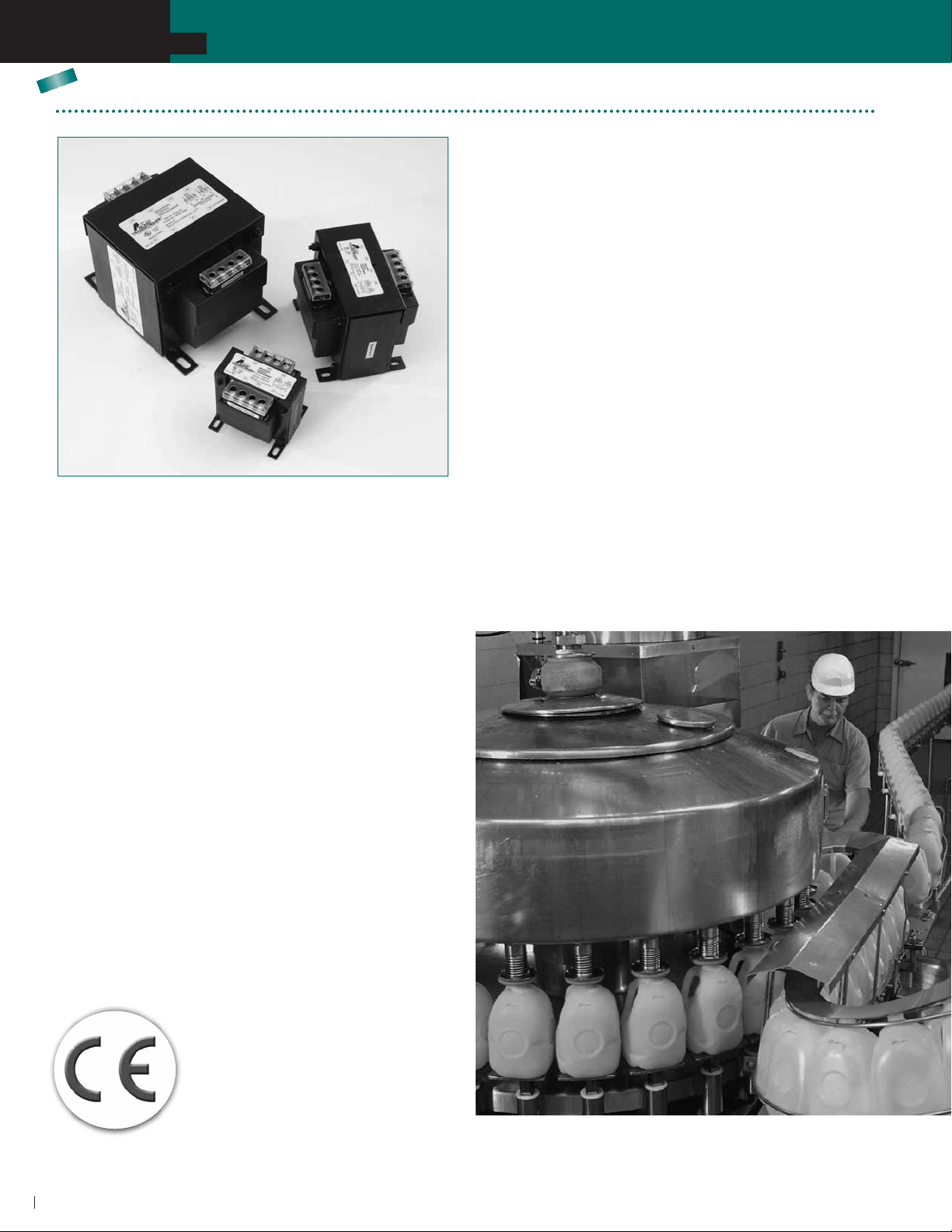
AE/CE Series Industrial Control Transformers
The Acme Electric AE and CE Series Industrial Control
T ransformers are designed specifically for machine tool control
circuit applications. These transformers have the ability to
handle potentially damaging high in-rush currents that occur
when electromagnetic components are energized, without
sacrificing the required stable output voltage. Designed to
meet or exceed the demands of international standards,
combined with the full breadth of product offering, the AE
and CE Series T ransformers from Acme Electric are the ideal
solution for your industrial control applications.
Cooler . Cleaner. More Compact.
The AE and CE Series design improves the dissipation of the
heat away from the core and coil assembly providing cooler
operation. In addition, the AE and CE Series industrial control
transformers seal the transformer’ s windings and internal
terminations within an epoxy encapsulant encased in a durable
thermoplastic end cap, protecting them from potentially
FEA TURES & BENEFITS
■
Epoxy encapsulated design protects core & coil assembly
from potentially damaging contaminants.
■
Integrally molded terminal blocks with isolation barriers to
prevent arc over , terminal blocks allow full access for ring
terminals for easy installation and solid termination.
■
Heavy gauge steel mounting feet.
■
Available factory or field installed fuse blocks provide
integral fusing on the primary or primary and secondary.
■
Dual labeling for easy product identification when equipped
with a fuse block.
■
50-750 V A, 50/60 Hz.
■
UL and cUL Listed, CE Marked (CE Series only).
■
T en-year limited warranty.
■
55°C T emperature Rise.
■
105°C Insulation Class.
damaging moisture, dirt and other ambient contaminants.
Furthermore, Acme’ s compact design helps minimize the
mounting footprint, providing more flexibility in applications
where space is at a premium.
CE Series for Global Applications
Acme’ s CE Series Encapsulated Industrial Control Transformers
carry the CE mark, indicating it complies with the requirements
established by the International Electrotechnical Commission
(IEC) for use of control circuit transformers in the
countries of the European Union. Regulations
that apply to control transformers include
Low Voltage Directive 73/23/EEC and
Electromagnetic Compatibility (EMC)
Directive 89/336/EEC.
80
SECTION
5
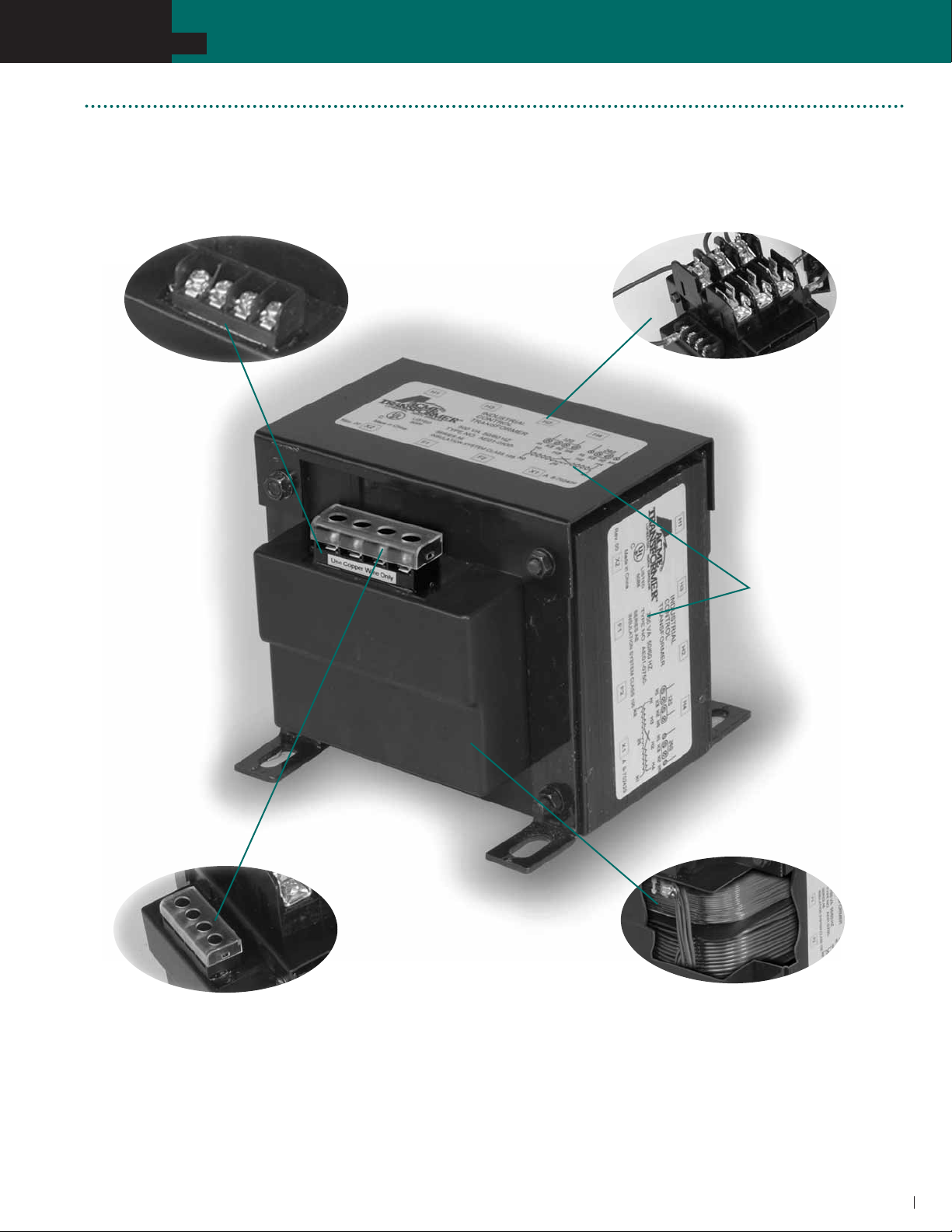
FEATURES
AE/CE SERIES INDUSTRIAL CONTROL TRANSFORMERS
Integrally molded terminal blocks with
combination slotted/phillips screws. Isolation barriers
protect against arc over while able to accommodate
a full ring terminal.
Integrally mounted fuse blocks
available in standard and touch-proof
(CE Series) style.
Dual labels for
identification
of fused modules
CE Series offers touch-proof terminals,
isolating live contacts for
additional safety.
Epoxy encapsulated copper windings
and internal terminations, providing
isolation from external contaminants
and physical damage.
81

SECTION
5
AE/CE SERIES INDUSTRIAL CONTROL TRANSFORMERS
SELECTION CHARTS CE SERIES
NEW
GROUP IC
120 x 240 PRIMARY VOLTS–– 24 SECONDARY VOLTS –– 1Ø, 50/60 Hz
VA
RATING CATALOG NUMBER A B C D E F SHIPPING WT
50 CE01-0050 2.69 (6.8) 3.00 (7.6) 2.81 (7.1) 2.25 (5.7) 2.56 (6.5)
75 CE01-0075 3.22 (8.1) 3.41 (8.6) 2.81 (7.1) 2.25 (5.7) 2.88 (7.3)
100 CE01-0100 3.28 (8.3) 3.75 (9.5) 3.09 (7.8) 2.53 (6.4) 3.13 (7.9)
150 CE01-0150 3.88 (9.8) 4.50 (11.4) 3.41 (8.6) 2.53 (6.4) 3.84 (9.7)
250 CE01-0250 4.13 (10.4) 4.50 (11.4) 4.03 (10.2) 3.22 (8.1) 3.84 (9.7)
350 CE01-0350 5.00 (12.7) 5.25 (13.3) 4.03 (10.2) 3.75 (9.5) 4.50 (11.4)
500 CE01-0500 5.50 (13.9) 5.25 (13.3) 4.66 (11.8) 4.28 (10.8) 4.50 (11.4) .31 x .69 (0.8 X 1.7) 19.1 (8.7)
750 CE01-0750 7.03 (17.8) 5.25 (13.3) 4.66 (11.8) 5.75 (14.6) 4.50 (11.4)
NEW
APPROX. DIMENSIONS INCHES (CM.) MOUNTING SLOT
.20 x .40 (0.5 x 1.0)
.20 x .40 (0.5 x 1.0)
.20 x .40 (0.5 x 1.0)
.20 x .40 (0.5 x 1.0)
.20 x .40 (0.5 x 1.0)
.31 x .69 (0.8 X 1.7)
.31 x .69 (0.8 X 1.7)
GROUP IIC
200/220/440, 208/230/460, 240/480 PRIMARY VOLTS –– 23/110, 24/115, 25/120 SECONDARY VOL TS –– 1Ø, 50/60 Hz
VA
RATING CATALOG NUMBER A B C D E F SHIPPING WT
50 CE02-0050 3.28 (8.3) 3.28 (8.3) 2.81 (7.1) 2.25 (5.7) 2.81 (7.1) .20 x .40 (0.5 x 1.0) 2.7 (1.2)
100 CE02-0100 4.03 (10.2) 3.75 (9.5) 3.13 (7.9) 3.22 (8.1) 3.16 (8.0)
150 CE02-0150 4.03 (10.2) 4.50 (11.4) 3.41 (8.6) 2.81 (7.1) 3.75 (9.5)
250 CE02-0250 4.78 (12.1) 4.50 (11.4) 4.03 (10.2) 4.06 (10.3) 3.75 (9.5)
350 CE02-0350 5.53 (14.0) 5.25 (13.3) 4.03 (10.2) 4.28 (10.8) 4.38 (11.1)
500 CE02-0500 7.25 (18.4) 5.25 (13.3) 4.69 (11.9) 6.00 (15.2) 4.38 (11.1)
750 CE02-0750 6.81 (17.3) 5.28 (13.4) 4.69 (11.9) 5.75 (14.6) 4.44 (11.2)
APPROX. DIMENSIONS INCHES (CM.) MOUNTING SLOT
.20 x .40 (0.5 x 1.0)
.20 x .40 (0.5 x 1.0)
.20 x .40 (0.5 x 1.0)
.31 x .69 (0.8 X 1.7)
.31 x .69 (0.8 X 1.7)
.31 x .69 (0.8 X 1.7)
C
APPROX.
2.5 (1.2)
3.5 (1.6)
4.2 (1.9)
6.6 (3.0)
9.4 (4.3)
13.0 (5.9)
26.6 (12.1)
APPROX.
4.3 (1.9)
6.8 (3.0)
9.7 (4.4)
13.5 (6.1)
19.6 (8.9)
27.0 (12.2)
NEW
GROUP IIIC
240 x 480 PRIMARY VOLTS–– 24 SECONDARY VOLTS –– 1Ø, 50/60 Hz
VA
RATING CATALOG NUMBER A B C D E F SHIPPING WT
50 CE03-0050 3.00 (7.6) 3.00 (7.6) 2.81 (7.1) 2.25 (5.7) 2.53 (6.4)
75 CE03-0075 3.28 (8.3) 3.28 (8.3) 2.81 (7.1) 2.25 (5.7) 2.81 (7.1) .20 x .40 (0.5 x 1.0) 3.5 (1.6)
100 CE03-0100 3.28 (8.3) 3.75 (9.5) 3.09 (7.8) 2.53 (6.4) 3.13 (7.9)
150 CE03-0150 3.88 (9.8) 4.50 (11.4) 3.47 (8.8) 2.53 (6.4) 3.75 (9.5)
250 CE03-0250 4.13 (10.4) 4.50 (11.4) 4.03 (10.2) 3.22 (8.1) 3.75 (9.5)
350 CE03-0350 5.00 (12.7) 5.25 (13.3) 4.03 (10.2) 3.75 (9.5) 4.38 (11.1)
500 CE03-0500 5.53 (14.0) 5.25 (13.3) 4.66 (11.8) 4.28 (10.8) 4.38 (11.1)
750 CE03-0750 7.03 (17.8) 5.25 (13.3) 4.66 (11.8) 5.41 (13.7) 4.38 (11.1)
84
APPROX. DIMENSIONS INCHES (CM.) MOUNTING SLOT
.20 x .40 (0.5 x 1.0)
.20 x .40 (0.5 x 1.0)
.20 x .40 (0.5 x 1.0)
.20 x .40 (0.5 x 1.0)
.31 x .69 (0.8 X 1.7)
.31 x .69 (0.8 X 1.7)
.31 x .69 (0.8 X 1.7)
APPROX.
2.5 (1.1)
4.0 (1.8)
6.5 (2.9)
9.2 (4.2)
12.7 (5.8)
19.0 (8.6)
26.0 (11.8)

SECTION
5
NEW
GROUP IVC
380/400/415 PRIMARY VOLTS–– 110/220 SECONDARY VOLTS–– 1Ø, 50/60 Hz
VA
RATING CATALOG NUMBER A B C D E F SHIPPING T
50 CE04-0050 3.53 (8.9) 3.00 (7.6) 2.81 (7.1) 2.53 (6.4) 2.53 (6.4)
100 CE04-0100 3.53 (8.9) 3.75 (9.5) 3.22 (8.1) 2.53 (6.4) 3.13 (8.0)
150 CE04-0150 3.53 (8.9) 4.34 (11.0) 3.41 (8.6) 2.53 (6.4) 3.75 (9.5)
250 CE04-0250 4.03 (10.2) 4.50 (11.4) 4.22 (10.7) 3.22 (8.1) 3.75 (9.5)
350 CE04-0350 4.91 (12.4) 4.50 (11.4) 4.22 (10.7) 4.06 (10.3) 4.38 (11.1)
500 CE04-0500 6.00 (15.2) 5.25 (13.3) 4.69 (11.9) 4.78 (12.1) 4.38 (11.1)
750 CE04-0750 6.81 (17.3) 5.25 (13.3) 4.69 (11.9) 5.75 (14.6) 4.38 (11.1)
NEW
GROUP VC
208, 220/380/440, 230/400/460, 240/416/480 PRIMARY VOLTS––
85/100/110, 91/110/120, 95/115/125, 99/120/130 SECONDARY VOLTS–– 1Ø, 50/60 Hz
VA
RATING CATALOG NUMBER A B C D E F SHIPPING T
50 CE05-0050 4.03 (10.2) 3.41 (8.6) 3.09 (7.8) 2.47 (6.2) 2.81 (7.1)
150 CE05-0150 3.88 (9.8) 4.34 (11.0) 3.41 (8.6) 2.88 (7.3) 3.75 (9.5)
250 CE05-0250 5.13 (13.0) 4.50 (11.4) 4.03 (10.2) 4.38 (11.1) 3.75 (9.5)
350 CE05-0350 5.91 (15.0) 5.25 (13.3) 4.03 (10.2) 4.78 (12.1) 4.38 (11.1)
500 CE05-0500 5.91 (15.0) 5.25 (13.3) 4.66 (11.8) 4.63 (11.7) 4.38 (11.1)
750 CE05-0750 7.09 (18.0) 5.25 (13.3) 4.66 (11.1) 5.81 (14.7) 4.38 (11.1)
AE/CE SERIES INDUSTRIAL CONTROL TRANSFORMERS
C
APPRO . DIMENSIONS INCHES (CM.) MOUNTING SLOT
.20 x .40 (0.5 x 1.0)
.20 x .40 (0.5 x 1.0)
.20 x .40 (0.5 x 1.0)
.20 x .40 (0.5 x 1.0)
.20 x .40 (0.5 x 1.0)
.31 x .69 (0.8 X 1.7)
.31 x .69 (0.8 X 1.7)
APPRO . DIMENSIONS INCHES (CM.) MOUNTING SLOT
.20 x .40 (0.5 x 1.0)
.20 x .40 (0.5 x 1.0)
.20 x .40 (0.5 x 1.0)
.31 x .69 (0.8 X 1.7)
.31 x .69 (0.8 X 1.7)
.31 x .69 (0.8 X 1.7)
APPRO .
2.6 (1.2)
4.3 (1.9)
6.7 (3.0)
9.4 (4.3)
13.0 (5.9)
18.8 (8.5)
26.0 (11.8)
APPRO .
2.7 (1.2)
6.7 (3.0)
9.5 (4.3)
13.3 (6.0)
19.0 (8.6)
27.0 (12.2)
NEW
GROUP VIC
240 x 480, 230 x 460, 220 x 440 PRIMARY VOLTS––120/115/110 SECONDARY VOLTS–– 1Ø, 50/60 Hz
VA
RATING CATALOG NUMBER A B C D E F SHIPPING T
50 CE06-0050 3.41 (8.6) 3.00 (7.6) 2.81 (7.1) 2.53 (6.4) 2.53 (6.4)
75 CE06-0075 3.41 (8.6) 3.28 (8.3) 2.81 (7.1) 2.53 (6.4) 2.81 (7.1)
100 CE06-0100 3.41 (8.6) 3.75 (9.5) 3.09 (7.8) 2.53 (6.4) 3.13 (7.9)
150 CE06-0150 3.88 (9.8) 4.50 (11.4) 3.47 (8.8) 2.53 (6.4) 3.75 (9.5)
250 CE06-0250 4.13 (10.4) 4.50 (11.4) 4.03 (10.2) 3.22 (8.1) 3.75 (9.5)
300 CE06-0300 4.53 (11.5) 4.50 (11.4) 4.03 (10.2) 3.75 (9.5) 3.75 (9.5)
350 CE06-0350 5.00 (12.7) 5.25 (13.3) 4.03 (10.2) 3.75 (9.5) 4.38 (11.1)
500 CE06-0500 6.00 (15.2) 5.25 (13.3) 4.66 (11.8) 4.78 (12.1) 4.38 (11.1)
750 CE06-0750 6.81 (17.3) 5.25 (13.3) 4.66 (11.8) 5.75 (14.6) 4.38 (11.1)
APPRO . DIMENSIONS INCHES (CM.) MOUNTING SLOT
.20 x .40 (0.5 x 1.0)
.20 x .40 (0.5 x 1.0)
.20 x .40 (0.5 x 1.0)
.20 x .40 (0.5 x 1.0)
.20 x .40 (0.5 x 1.0)
.20 x .40 (0.5 x 1.0)
.31 x .69 (0.8 X 1.7)
.31 x .69 (0.8 X 1.7)
.31 x .69 (0.8 X 1.7)
APPRO .
2.6 (1.2)
3.6 (1.6)
4.3 (1.9)
6.7 (3.0)
9.4 (4.3)
10.9 (4.9)
13.0 (5.9)
18.8 (8.5)
26.0 (11.8)

SECTION
5
AE/CE INDUSTRIAL CONTROL TRANSFORMERS
FUSE SIZING CHAR TS
PRIMARY FUSE SIZING CHARTS
RECOMMENDED RATING FOR CURRENT LIMITING CLASS CC FUSES
120 V 208 V 220 V 230 V 240 V 380 V 400 V 416 V 440 V 460 V 480 V 500 V 550 V 575 V 600 V
50 VA 1.25 0.60 0.60 0.60 0.60 0.30 0.30 0.30 0.30 0.30 0.30 0.30 0.25 0.25 0.25
75 VA 1.80 1.00 1.00 0.80 0.80 0.50 0.50 0.50 0.50 0.40 0.40 0.40 0.40 0.30 0.30
100 VA 2.50 1.40 1.25 1.25 1.25 0.75 0.75 0.60 0.60 0.60 0.60 0.60 0.50 0.50 0.50
150 VA 3.50 2.00 2.00 1.80 1.80 1.13 1.13 1.00 1.00 0.80 0.80 0.80 0.80 0.75 0.75
250 VA 3.20 3.50 3.20 3.20 3.00 1.80 1.80 1.80 1.60 1.60 1.50 1.50 1.25 1.25 1.25
300 VA 4.00 4.00 4.00 3.50 3.50 2.25 2.25 2.00 2.00 1.80 1.80 1.80 1.60 1.50 1.50
350 VA 4.50 5.00 4.50 4.50 4.00 2.50 2.50 2.50 2.25 2.25 2.00 2.00 1.80 1.80 1.60
500 VA 6.25 4.00 3.50 3.50 3.20 3.50 3.50 3.50 3.20 3.20 3.00 3.00 2.50 2.50 2.50
750 VA 10.00 6.00 5.60 5.00 5.00 5.60 5.60 5.00 5.00 4.50 4.50 4.50 4.00 3.50 3.50
NOTE: Bold lines indicate changes in the percent of rated current used to calculate fuse sizes in accordance with article 450 of the NEC.
SECONDARY FUSE SIZING CHARTS
RECOMMENDED RATING FOR CURRENT LIMITING MIDGET FUSES
24 V 85 V 91 V 95 V 99 V 100 V 110 V 115 V 120 V 125 V 130 V
50 VA 2.00 0.50 0.50 0.50 0.50 0.50 0.50 0.50 0.50 0.50 0.25
75 VA 3.00 – – – – – 0.75 0.75 0.75 – –
100 VA 5.00 – – – – – 1.00 1.00 1.00 – –
150 VA 6.00 2.00 2.00 1.50 1.50 1.50 1.50 1.50 1.50 1.50 1.00
250 VA 12.00 3.00 3.00 3.00 3.00 3.00 2.00 2.00 2.00 2.00 2.00
300 VA – – – – – – 3.00 3.00 3.00 – –
350 VA 15.00 5.00 4.00 4.00 4.00 4.00 3.00 3.00 3.00 3.00 3.00
500 VA 25.00 6.00 6.00 6.00 6.00 6.00 5.00 5.00 5.00 5.00 4.00
750 VA 35.00 10.00 10.00 8.00 8.00 8.00 8.00 8.00 6.00 6.00 6.00
CONNECTION DET AILS FOR AE05 & CE05
H1-H2 H1-H3 H1-H4 1- 2 1- 3 1- 4
208 85 100 110
220 380 440 91 110 120
230 400 460 95 115 125
240 416 480 99 120 130
6
 Loading...