

Page 1
®
DRAFT 8-27-2015
Synergize™ RF Network
GE I-210
Integration Manual
Y20454-INT Rev. A
The information contained in this document is private to Aclara Technologies LLC, an Ohio limited liability company
(Aclara). This information may not be published, reproduced, or otherwise disseminated without the express written
authorization of Aclara. Any software or firmware described in this document is furnished under a license and may be
used or copied only in accordance with the terms of such license.
The information in this document is subject to change without notice and should not be construed as a commitment
by Aclara. Aclara assumes no responsibility for any errors that may appear in this document. No responsibility is
assumed for the use or reliability of software on equipment that is not supplied by Aclara. TWACS, STAR, and Metrum
Cellular are registered trademarks of Aclara Technologies LLC.
www.Aclara.com
PROPRIETARY NOTICE
DISCLAIMER
Page 2

DRAFT 8-27-2015
Page 3

FCC Compliance
DRAFT 8-27-2015
This equipment has been tested and found to comply with the limits for a Class B
digital device, pursuant to part 15 of the FCC Rules. These limits are designed to
provide reasonable protection against harmful interference in a residential
installation. This equipment generates, uses, and can radiate radio frequency
energy and, if not installed and used in accordance with the instructions, may
cause harmful interference to radio communications. However, there is no
guarantee that interference will not occur in a particular installation. If this
equipment does cause harmful interference consult Aclara Support for help.
Safety Information
The following safety precautions must be observed during all phases of operation,
service, and repair of this device. Failure to comply with these precautions or with
specific warnings elsewhere in this manual violates safety standards of design,
manufacture, and the intended use of the metering instrument. Aclara assumes no
liability for the customer’s failure to comply with these requirements.
W
ARNING
Any work on, or near, energized meters, meter sockets, or other metering
equipment can present a danger of electrical shock. All work on this product
should be performed only by qualified electricians and metering specialists in
accordance with local utility safety practices, utility requirements and
procedures outlined in Chapter 14 of The Handbook for Electricity Metering
(10th edition).
The information contained within this manual is intended to be an aid to qualified
metering personnel. It is not intended to replace the extensive training necessary to
handle metering equipment in a safe manner.
• Use care when servicing with the power on.
• Do not assume neutral (white lead) is always at earth ground potential. Some
services have this connection at line voltage.
• Be aware that dangerous voltages exist at several points within the meter
when this product is installed on a meter base.
• Disconnect power before meter disassembly, soldering, or replacing
components.
The meter is connected directly to line potential. Due to the possibility of the
potential lines being reversed, points accessible with the cover off may be at line
voltage.
Consult the meter instruction/technical manual for meter specific information.
Synergize™ RF Network GE I-210 Integration Manual 1
Page 4
Synergize™ RF Network GE I-210 Meter Integration
DRAFT 8-27-2015
Synergize™ RF Network GE I-210 Meter Integration
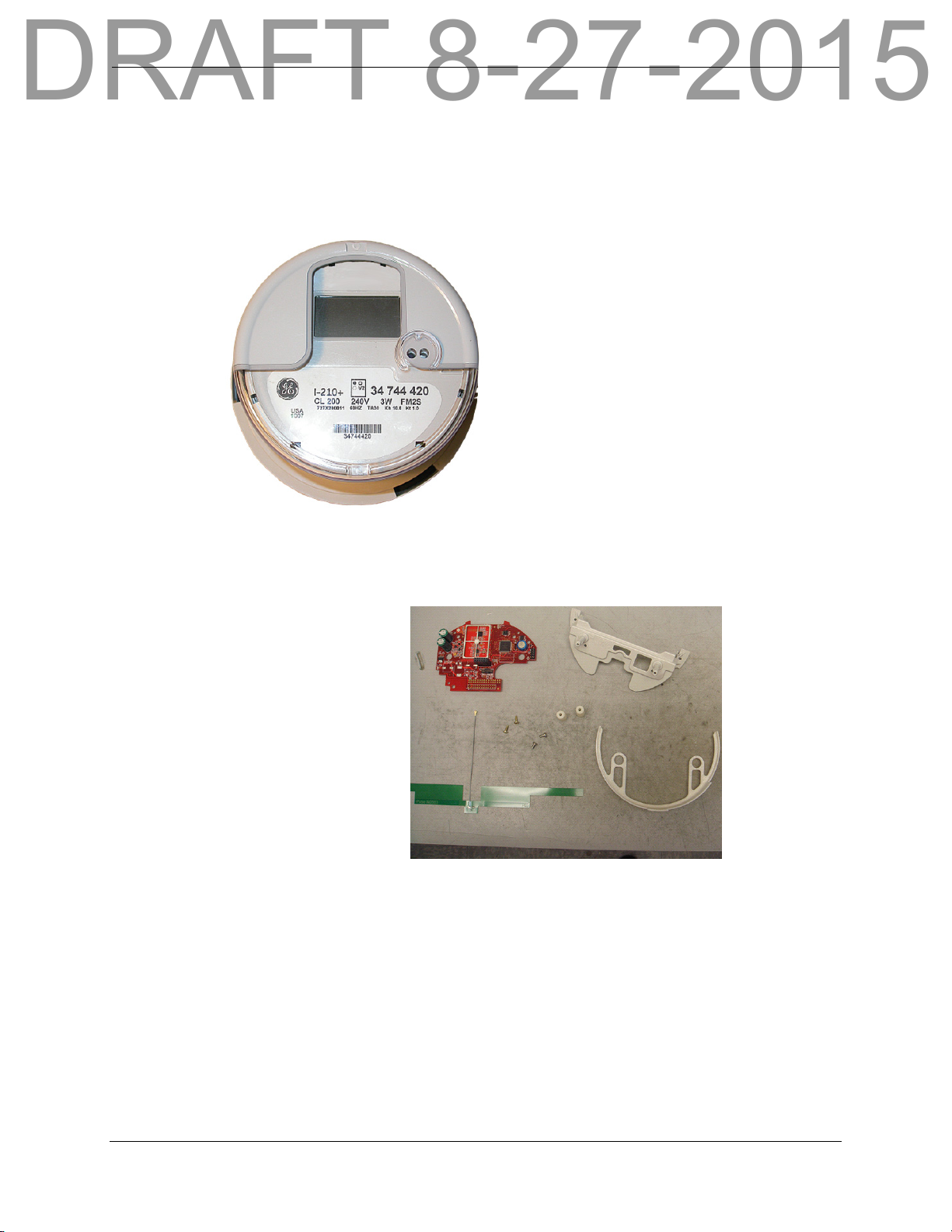
This document provides an overview of the material and steps required to integrate
an Aclara Synergize™ RF Network endpoint module with a new or existing GE
I-210 meter.
Components Needed
• Antenna
•Meter
• Bridge
• Bridge Screws
• RF board
• Antenna holder
• Bushings/Stand-offs
• Bushing/stand-off
screws
I-210 Integration
1. Put on an ESD strap.
2. Remove the meter cover.
2 Synergize™ RF Network GE I-210 Integration Manual
Page 5
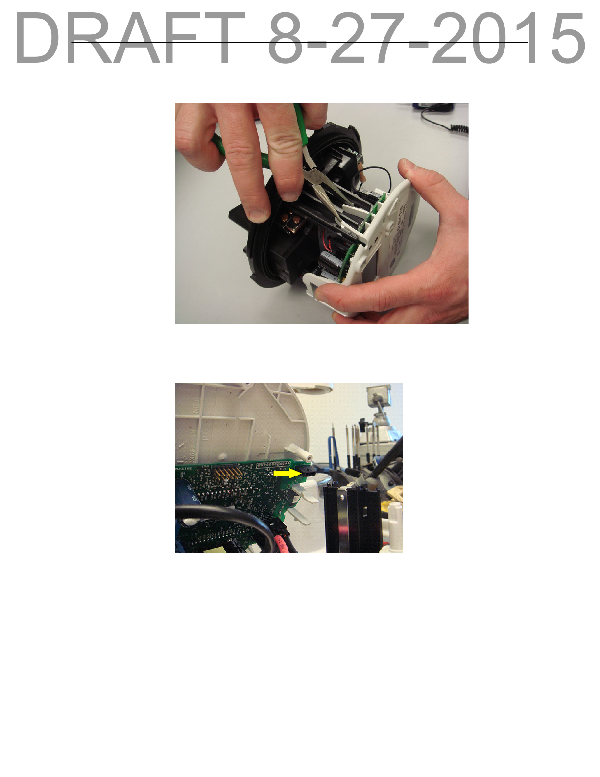
3. Remove the top of the meter by squeezing the pair of clips on each side of
DRAFT 8-27-2015
the meter.
4. Disconnect the remote disconnect wire from the top of the meter, if the
meter has the remote disconnect option,
Synergize™RF Network GE I-210 Integration Manual 3
Page 6
Synergize™ RF Network GE I-210 Meter Integration
DRAFT 8-27-2015
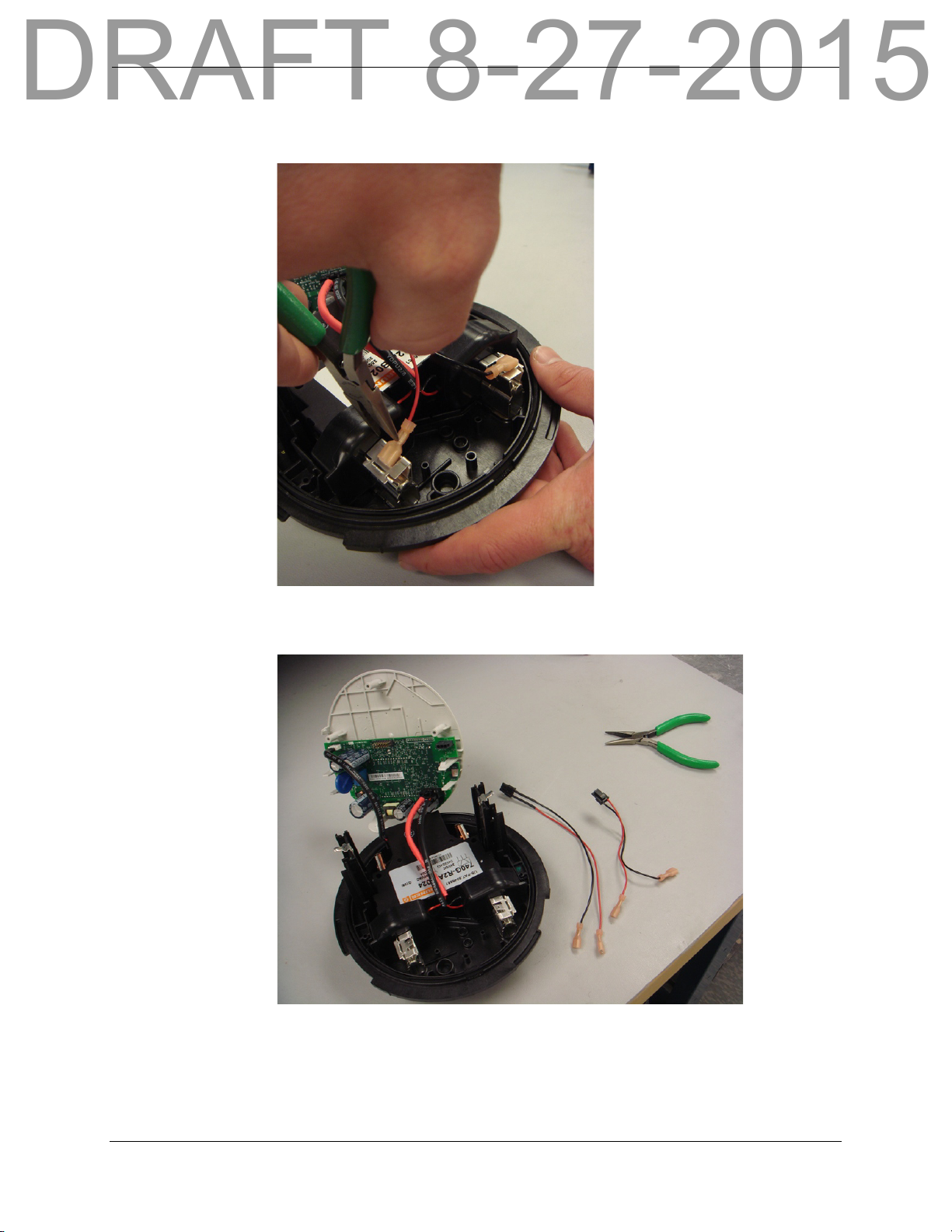
5. Remove the red remote disconnect wire from the metal clip on the meter
base.
6. Remove the black remote disconnect wire from the metal clip on the meter
base.
4 Synergize™ RF Network GE I-210 Integration Manual
Page 7
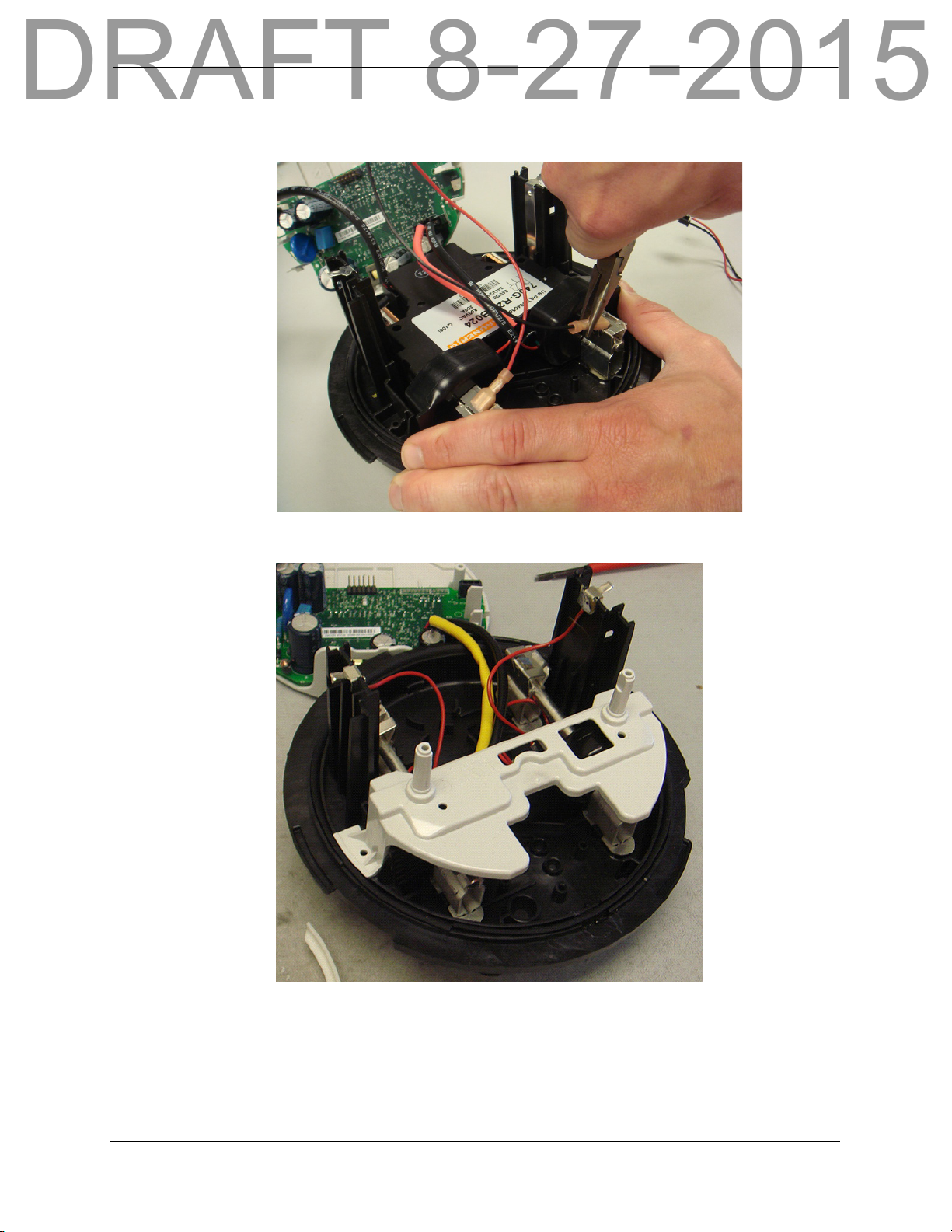
7. Attach the longer red and black remote disconnect wires as shown in the
DRAFT 8-27-2015
following image.
8. Verify the GE-supplied bridge is properly positioned on the meter base.
Synergize™RF Network GE I-210 Integration Manual 5
Page 8

Synergize™ RF Network GE I-210 Meter Integration
DRAFT 8-27-2015
9. Secure the bridge to the meter base using the two screws.
N
OTE
If the meter has the remote disconnect option, carefully pull the remote
disconnect wire underneath the bridge so it can be properly routed in Step 12.
10. Remove the backing from the antenna.
6 Synergize™ RF Network GE I-210 Integration Manual
Page 9

11. Affix the antenna to the antenna holder.
DRAFT 8-27-2015
N
OTE
When applying the antenna, maximum bond strength can be obtained by
thoroughly cleaning and drying the surface of the antenna holder with
isopropyl alcohol. For applications such as this, it is important to use
reagent grade solvents. Common household materials, such as rubbing
alcohol, frequently contain oils to minimize the drying affect on skin, and
can interfere with the performance of a pressure-sensitive adhesive.
Synergize™RF Network GE I-210 Integration Manual 7
Page 10

Synergize™ RF Network GE I-210 Meter Integration
DRAFT 8-27-2015
12. Place the antenna holder over the posts on the bridge.
N
OTE
If the meter has the Remote Disconnect option, make sure the Remote
Disconnect wire is routed between the bridge and the antenna holder.
8 Synergize™ RF Network GE I-210 Integration Manual
Page 11

13. Install the RF board over the bridge posts.
DRAFT 8-27-2015
14. Place the bushings/standoffs over the bridge posts.
Synergize™RF Network GE I-210 Integration Manual 9
Page 12

Synergize™ RF Network GE I-210 Meter Integration
DRAFT 8-27-2015
15. Secure the bushings using the two screws.
N
OTE
16. Connect the antenna wire to the connector on the RF board.
It is not required, but a Plug Insertion Tool (HRS U.FL-LP-IN) is available for
mating U.FL series plugs and receptacles.
10 Synergize™ RF Network GE I-210 Integration Manual
Page 13

17. Align the 12 pin connector on the under-side of the meter top to the
DRAFT 8-27-2015
connector on the RF board.
N
OTE
Synergize™RF Network GE I-210 Integration Manual 11
If the meter has the remote disconnect option, align the connector on the
remote disconnect wire to the connector on the underside of the meter top.
Page 14

Synergize™ RF Network GE I-210 Meter Integration
MAC ID Label
FCC Label
DRAFT 8-27-2015
18. Press the top of the meter into place. Ensure the retaining tabs lock in place.
19. Place the MAC ID label above the LCD and place the FCC label below the
LCD as shown in the following image.
20. Reinstall the meter cover.
12 Synergize™ RF Network GE I-210 Integration Manual
Page 15

Support
DRAFT 8-27-2015
There are several ways to get help when you have a question, an issue, or would
like to speak with Aclara’s Support personnel.
• Aclara Connect
Aclara's exciting customer portal (https://connect.aclara.com) enables you
to access our frequently-updated knowledge database, easily access product
documentation, submit and track your Support cases and RMAs, access
Aclara University's Online Learning Center (OLC) and learning library,
track your orders, join communities and groups, join in discussions with
other Aclara customers and Aclara personnel, and much more. If you do not
have access to Aclara Connect, email support@aclara.com and request
access.
• Aclara University
Aclara’s on-demand training makes content available to you in a
convenient, cost-effective online environment. The OLC has recordings of
several webinars, streaming educational videos, software simulations, and
short videos which walk you through a specific task. Access the OLC by
going the Training tab of Aclara Connect and clicking the Online Learning
Center link.
• Technical Support
Email support@aclara.com or call 1-800-892-9008 to speak with an Aclara
representative.
Synergize™RF Network GE I-210 Integration Manual 13
Page 16

Support
DRAFT 8-27-2015
14 Synergize™ RF Network GE I-210 Integration Manual
Page 17

C
DRAFT 8-27-2015
HAPTER
0
A
PPENDIX
Only the GE I-210 (JV103X677) meter forms listed below are qualified to be
integrated with the Aclara Synergize™ RF Network module.
Class and
Meter Form
1S
1SRD CL100, 120V Y84024-1 Y84024-301 1.0
2S
2SRD CL200, 240V Y84024-1 Y84024-301 1.0
3S CL20, 240V Y84024-1 Y84024-301 1.0
4S CL20, 240V Y84024-1 Y84024-301 1.0
12S
12SRD CL200, 120V Y84024-1 Y84024-301 1.0
25S CL200, 240V Y84024-1 Y84024-301 1.0
Voltage
CL100, 120V Y84024-1 Y84024-301 1.0
CL100, 240V Y84024-1 Y84024-301 1.0
CL200, 240V Y84024-1 Y84024-301 1.0
CL320, 240V Y84024-1 Y84024-301 1.0
CL200, 120V Y84024-1 Y84024-301 1.0
CL320, 120V Y84024-1 Y84024-301 1.0
A: F
ORM
& M
Aclara GE
I-210+ Modules
ODULE
Aclara GE
I-210+ RD
Modules
P/N
S
Kh Value
GE I210+ and I210+ with Remote Disconnect Integration Manual 15
Page 18

16 GE I210+ and I210+ with Remote Disconnect Integration Manual
DRAFT 8-27-2015
Page 19

C
6 6
3
6
3
6
6
3
6
3
6
3
DRAFT 8-27-2015
HAPTER
0
A
PPENDIX
B: W
IRING
D
IAGRAMS
Synergize™ RF Network GE I-210 Integration Manual 17
Page 20

18 Synergize™ RF Network GE I-210 Integration Manual
DRAFT 8-27-2015
Page 21

Synergize™ RF Network Endpoint Module
Electrical Specifications
Parameter Rating
Input Voltage 4.0 VDC or optional 28VDC
Quiescent Current 70 mA @ 4 VDC
Current while transmitting RF <800 mA @ 4 VDC
Power Supply DC energy is provided by the host
Environmental Specifications
Parameter Rating
Effect of Operating Temperature Aclara specific test
-40° C to 70° C with and without solar load
Effect of Relative Humidity Aclara specific test
60° C for thee 24 hour cycles or 85° C for one 24 hour cycle at 95±
4% relative humidity, non-condensing
Physical Specifications
Tes t Ti t l e Specification
Approximate weight < 3 oz.
Dimensions Irregular
Compliance Specifications
Tes t Ti t l e Specification
EMI/RFI Emission Conducted/Radiated
EMI/RFI Susceptibility RF Susceptibility ANSI C12.1 Test #26 200 kHz to
FCC Part 90 Subpart I, emission mask D
Occupied Bandwidth 11.25 kHz
RF Output Power <
Carrier Frequency Stability ± 2.5 ppm
Note: This device complies with Part 15 of the FCC Rules. Operation is subject to the following two conditions: (1) This device
may not cause harmful interference, and (2) This device must accept any interference received, including interference that may
cause undesired operation. This product complies with FCC OET Bulletin 65 & Industry Canada's RSS-102 radiation exposure
limits set forth for an uncontrolled environment.Aclara Technologies LLC low power RF devices and their antennas must be
fixed-mounted on indoor or outdoor permanent structure(s) providing a separation distance of at least 20 cm from all persons
during normal operation. This device is not designed (and it has no external connection) to operate in conjunction with any other
antennas or transmitters. No other operating instructions for satisfying RF exposure compliance are needed.
FCC 15.107 Conducted Emissions IEC CISPR 22
FCC 15.109 Unintentional Radiator IEC CISPR 22
10 GHz 20 V/m
+30 dBm
Transmit duty cycle <
2%
NOTICE: This device is certified by th e Federal Communications Commissi on for use pursuant to a station au thorization. TWACS®, STAR®, and Metrum Cellular® are registered trademarks of
Aclara Technologies LLC an O hio limited liability company (Aclara). All software is property of Aclara. Patents issued and pending. Aclara reserves the right to change the specifications on this
product without prior notification. Copyright Aclara Technologies LLC 2015.
 Loading...