

Page 1

Technical Brief
DRAFT
MTU Installation Requirements
A product of
Aclara Technologies LLC
Confidential and Proprietary
Copyright 2013-16. All Rights Reserved.
(Y20355-TEB Rev F)
This document contains information that is private to Aclara Technologies LLC, an Ohio limited liability
company, and/or that is private to Aclara Meters LLC, a Delaware limited liability company (individually or
collectively “Aclara”). This information may not be published, reproduced, or otherwise disseminated without
the express written authorization of Aclara.
Any software or firmware described in this document is furnished under a license and may be used or copied
only in accordance with the terms of such license.
The information in this document is subject to change without notice and should not be construed as a
commitment by Aclara. Aclara assumes no responsibility for any errors that may appear in this document.
No responsibility is assumed for the use or reliability of software on equipment that is not supplied by Aclara.
TWACS, STAR, and Metrum Cellular are registered trademarks of Aclara Technologies LLC.
PROPRIETARY NOTICE
DISCLAIMER
Page 2

DRAFT
Page 3

Table of Contents
DRAFT
Warnings, Cautions, and Notes
FCC/IC Compliance. . . . . . . . . . . . . . . . . . . . . . . . . . . . iii
FCC/IC RF Exposure Guide . . . . . . . . . . . . . . . . . . . . . . . . iv
Field Calibration Procedure . . . . . . . . . . . . . . . . . . . . . . . iv
Avertissements, mises en garde et remarques
Conformité FCC/IC . . . . . . . . . . . . . . . . . . . . . . . . . . . . v
Guide d'exposition aux RF FCC/IC. . . . . . . . . . . . . . . . . . . . . vi
Procédure de calibration sur place . . . . . . . . . . . . . . . . . . . . vi
Overview
Support . . . . . . . . . . . . . . . . . . . . . . . . . . . . . . . . . 1
Deployment Process . . . . . . . . . . . . . . . . . . . . . . . . . . . 2
Signal Propagation . . . . . . . . . . . . . . . . . . . . . . . . . . . . 3
Free Space Attenuation . . . . . . . . . . . . . . . . . . . . . . . . . 4
RF Absorption. . . . . . . . . . . . . . . . . . . . . . . . . . . . . . 4
RF Reflection . . . . . . . . . . . . . . . . . . . . . . . . . . . . . . 5
RF Shadowing. . . . . . . . . . . . . . . . . . . . . . . . . . . . . . 6
Mounting Considerations
Exterior Mounting . . . . . . . . . . . . . . . . . . . . . . . . . . . . 9
Interior . . . . . . . . . . . . . . . . . . . . . . . . . . . . . . . . . 13
Pipe Mounting . . . . . . . . . . . . . . . . . . . . . . . . . . . . . . 16
Meter Pit . . . . . . . . . . . . . . . . . . . . . . . . . . . . . . . . 17
Without Spacers . . . . . . . . . . . . . . . . . . . . . . . . . . . . 18
Spacers . . . . . . . . . . . . . . . . . . . . . . . . . . . . . . . . 19
Short Spacers. . . . . . . . . . . . . . . . . . . . . . . . . . . . . 19
Long Spacers . . . . . . . . . . . . . . . . . . . . . . . . . . . . . 20
Wiring
Cable Insulation . . . . . . . . . . . . . . . . . . . . . . . . . . . . . 21
Wire Length . . . . . . . . . . . . . . . . . . . . . . . . . . . . . . . 21
Wire Routing. . . . . . . . . . . . . . . . . . . . . . . . . . . . . . . 21
Connections . . . . . . . . . . . . . . . . . . . . . . . . . . . . . . . 22
Interior/Exterior Environment . . . . . . . . . . . . . . . . . . . . . . 22
Meter Pit Environment. . . . . . . . . . . . . . . . . . . . . . . . . . 23
Appendix: Equipment
Appendix: Checklist
MTU Installation Requirements i
Page 4

Table of Contents
DRAFT
ii MTU Installation Requirements
Page 5

W
DRAFT
ARNING
C
AUTION
N
W
ARNINGS
Always consult and adhere to all local and national safety codes, regulations, and
standards.WARNING, CAUTION and Note statements are used throughout this
manual to emphasize important and critical information to help you ensure safety
and prevent product damage.These statements are defined below.
indicates a potentially hazardous situation which, if not avoided, could result in
death or serious physical injury.
indicates a situation, which, if not avoided, could result in damage to
equipment, damage to software, loss of data or invalid results.
OTE
indicates important supplemental information.
, C
AUTIONS, AND
N
OTES
FCC/IC Compliance
This equipment has been tested and found to comply with the limits for a Class B
digital device, pursuant to part 15 of the FCC Rules. These limits are designed to
provide reasonable protection against harmful interference in a residential
installation. This equipment generates, uses and can radiate radio frequency
energy and, if not installed and used in accordance with the instructions, may
cause harmful interference to radio communications. However, there is no
guarantee that interference will not occur in a particular installation. If this
equipment does cause harmful interference to radio or television reception, which
can be determined by turning the equipment off and on, the user is encouraged to
try to correct the interference by one or more of the following measures:
• Reorient or relocate the receiving antenna.
• Increase the separation between the equipment and receiver.
• Connect the equipment into an outlet on a circuit different from that to which
the receiver is connected.
• Consult the dealer or an experienced radio/TV technician for help.
C
AUTION
Any changes or modification made to this device without the expressed,
written approval of Aclara Technologies LLC may void the user's authority to
operate this device.
MTU Installation Requirements iii
Page 6

FCC/IC Compliance
DRAFT
FCC/IC RF Exposure Guide
Aclara Technologies LLC low power RF devices and their antennas must be
fixed-mounted on indoor or outdoor permanent structure(s) providing a separation
distance of at least 20 cm from all persons during normal operation. This device is
not designed to operate in conjunction with any other antennas or transmitters. No
other operating instructions for satisfying RF exposure compliance are needed.
Field Calibration Procedure
Aclara Technologies LLC low power RF devices have passed through extensive
testing and calibration procedures while in the factory. Therefore, no additional
calibration or adjustment is required in the field.
iv MTU Installation Requirements
Page 7

A
DRAFT
VERTISSEMENTS
Toujours consulter et respecter les codes, règlements et normes de sécurité locaux
et nationaux. Des AVERTISSEMENTS, MISES EN GARDE et remarques sont
utilisés tout au long de ce guide pour souligner l'information importante et critique
qui vous aidera à assurer la sécurité et à prévenir les dommages au produit. Ces
énoncés sont définis ci-dessous.
A
VERTISSEMENT
indique une situation potentiellement dangereuse qui, si elle n'était pas évitée,
pourrait entraîner la mort ou des blessures graves.
M
ISE EN GARDE
indique une situation qui, si elle n'était pas évitée, pourrait entraîner des
dommages à l'équipement, des dommages au logiciel, des pertes de données ou
des résultats invalides.
Avertissements, mises en garde et remarques
,
MISES EN GARDE ET REMARQUES
R
EMARQUE
indique des informations supplémentaires importantes.
Conformité FCC/IC
Cet équipement a été testé et il est conforme aux limites pour un appareil
numérique de Classe B, en vertu de l'article 15 des règlements de la FCC. Ces
limites sont conçues pour offrir une protection raisonnable contre l'interférence
nuisible dans une installation résidentielle. Cet équipement génère, utilise et peut
émettre de l'énergie de fréquences radio et, s'il n'est pas installé ou utilisé
conformément aux instructions, il peut causer une interférence nuisible aux
communications radio. Il n'existe toutefois aucune garantie que de telles
interférences ne se produiront pas dans une installation particulière. Si cet appareil
cause des interférences nuisibles à la réception des signaux de radio ou de
télévision, ce qui peut être détecté en mettant l'appareil sous et hors tension,
l'utilisateur peut tenter de neutraliser l'interférence de l'une ou l'autre des façons
suivantes :
• Réorienter ou repositionner l'antenne de réception.
• Augmenter la distance séparant l'équipement du récepteur.
• Brancher l'appareil dans une prise sur un circuit électrique différent de celui
sur lequel le récepteur est branché.
MISE EN
GARDE
MTU Installation Requirements v
• Consulter le fournisseur ou un technicien radio ou télévision expérimenté.
Tout changement ou toute modification à cet appareil sans l'approbation
écrite expresse d'Aclara Technologies LLC peut annuler l'autorisation de
l'utilisateur d'utiliser cet appareil.
Page 8

Conformité FCC/IC
DRAFT
Guide d'exposition aux RF FCC/IC
Les appareils RF à faible puissance Aclara Technologies LLC ainsi que leurs
antennes doivent être montés de manière fixe sur des structures intérieures ou
extérieures permanentes qui se trouvent à au moins 20 cm des personnes pendant
le fonctionnement normal. Cet appareil n'est pas conçu (et il n'a aucun
branchement externe) pour être utilisé en association avec toute autre antenne ou
tout transmetteur. Aucune autre instruction d'utilisation n'est requise pour assurer
la conformité aux règles d'exposition aux RF.
Procédure de calibration sur place
Les appareils RF à faible puissance Aclara Technologies LLC ont été soumis à des
tests étendus et multi-tâches et à des procédures de calibration complexes en usine.
Par conséquent, ils ne requièrent pas de calibration ni d'ajustement supplémentaire
sur place. Les appareils RF à faible puissance Aclara Technologies LLC sont
expédiés au client dans des boîtiers scellés. Aucun ajustement ne peut donc être
effectué sur place sans briser le boîtier scellé en usine.
vi MTU Installation Requirements
Page 9

Support
DRAFT
O
VERVIEW
Meter Transmission Units (MTUs) are the endpoints of the STAR system. MTUs
are permanently sealed devices that transmit regularly scheduled meter readings
on an FCC licensed frequency to a Data Collector Unit, or DCU. Every Meter
Transmission Unit (MTU) installation location presents its own set of variables.
This document is intended to help guide installers by providing general
information about UHF radio transmissions, MTUs, and Aclara required practices
for installation. Failure to adhere to these guidelines may be detrimental to system
operation.
There are several ways to get help when you have a question, an issue, or would
like to speak with Aclara's Support personnel.
• Aclara Connect
Aclara's exciting customer portal (https://connect.aclara.com) enables you to
access our frequently-updated knowledge database, easily access product
documentation, submit and track your Support cases and RMAs, access
Aclara University's Online Learning Center (OLC) and learning library,
track your orders, join communities and groups, join in discussions with
other Aclara customers and Aclara personnel, and much more. If you do not
have access to Aclara Connect, email support@aclara.com and request
access.
• Aclara University
Aclara's on-demand training makes content available to you in a convenient,
cost-effective online environment. The OLC has recordings of several
webinars, streaming educational videos, software simulations, and short
videos which walk you through a specific task. Access the OLC by going to
the Training tab of Aclara Connect and clicking the Online Learning Center
link.
• Technical Support
Email support@aclara.com or call 1-800-892-9008 to speak with an Aclara
representative.
MTU Installation Requirements 1
Page 10

Deployment Process
DRAFT
Deployment Process
MTU deployment can be broken down into three basic steps. These are:
1. Mounting the MTU
2. Routing and connecting the wiring
3. Programming and configuring the MTU
The scope of this document is limited to the mounting and wiring portions of the
deployment process. For more information on programming MTUs, please refer to
the following manuals:
STAR Programmer Software Installation Instructions (Y20318-TUM)
Provides detailed instructions for installing the STAR Programmer Software.
STAR Programmer Software User Guide (Y20348-TUM)
Provides information that enables you to program and configure MTUs using the
STAR Programmer Software.
2 MTU Installation Requirements
Page 11
Signal Propagation
DRAFT
The STAR Network operates in the range of 450 - 470 Megahertz (MHz).
Frequencies in this range are specifically licensed by the FCC for business use, and
are considered to be part of the Ultra-High Frequency (UHF) band of radio
communications. As with all UHF communications, there are certain factors that
affect the propagation of the radio transmissions. The STAR Network is designed
to overcome these factors, but failure to follow these installation guidelines may
create conditions that exceed the limits of the STAR Network.
All devices that operate in the UHF band are considered to use line of sight
transmission, and operate best when the path between the transmission point and
the reception point is unobstructed.
Overview
MTU Installation Requirements 3
Every Meter Transmission Unit (MTU) installation location presents its own set of
variables, and this document is intended to help guide installers by providing
general information about UHF radio transmissions and MTUs.
There are four main things that affect the propagation of UHF radio waves. These
are free space attenuation, absorption, reflection, and shadowing.
Page 12

Signal Propagation
DRAFT
Free Space Attenuation
Free space attenuation is the natural loss in signal strength that occurs when radio
waves pass through open air. This loss in signal strength is proportionate to the
distance between the transmitter and the receiver. While the actual installation of
the MTU will not change the free space attenuation considerably, certain locations
may require the use of an extended range MTU or additional DCUs to improve
communication.
RF Absorption
RF absorption occurs naturally with objects that are not electrically conductive
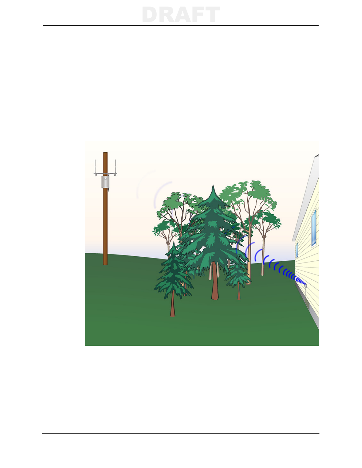
such as drywall, concrete, wood, and foliage. A variety of factors affect how much
RF energy is absorbed by the obstruction. The following illustrates how concrete
tends to absorb more RF energy than a sheet of drywall.
4 MTU Installation Requirements
Page 13

RF Reflection
DRAFT
RF reflection occurs when objects made of conductive materials (typically metal)
are in or near the transmission path. While reflection itself may not negatively
affect system performance, the RF signal may be reflected into an absorbing
material such as dense foliage or the concrete foundation of a building. Common
objects that reflect RF signals are metal buildings such as sheds or warehouses,
metal fences, HVAC ducts, vehicles, and metal signs. It is important to note that
even metal fences that are not solid (e.g. chain-link, wrought iron) will reflect a
large portion of the RF signals.
Overview
MTU Installation Requirements 5
Page 14

Signal Propagation
DRAFT
RF Shadowing
RF shadowing is a phenomenon related to absorption and reflection that occurs
when a transmitter is too close to another object. Shadowing occurs when a nearby
object absorbs or reflects a signal. The image below illustrates how the downspout,
iron pipe, and the AC unit all shadow the RF signal.
6 MTU Installation Requirements
Page 15

Overview
DRAFT
The signal is narrowest when it first leaves the MTU. The closer an object is to the
MTU, the greater the impact the object will have on the signal. This is illustrated in
the image below, where the close proximity of the garbage dumpster is blocking
the signal from the MTU.
Simply moving the dumpster several feet away from the MTU allows a greater
portion of the signal to propagate.
MTU Installation Requirements 7
Page 16

Signal Propagation
DRAFT
8 MTU Installation Requirements
Page 17

M
DRAFT
OUNTING
The following sections describe the nature of RF signal transmission in the UHF
frequency range, and specific factors to consider when installing an MTU on the
exterior of a building, inside a building, or in a meter pit. Regardless of the
installation environment, the MTU must be mounted securely.
Exterior Mounting
Issues with performance of exterior mounted MTUs are typically the result of
mounting the MTU too low, or mounting it in such a way that it is blocked by
various obstructions.
In the following real world example, the MTU is mounted between the protruding
exterior wall and the hose reel, both of which absorb the RF signal.
C
ONSIDERATIONS
Raising the MTU above the hose reel will reduce the amount of signal absorbed,
but a better solution is to move the MTU to the front of the building, as shown
below.
MTU Installation Requirements 9
Page 18

Exterior Mounting
DRAFT
In this example, the RF signal is reflected off of the iron fence and absorbed by the
exterior wall of the home.
Simply raising the MTU above the fence and moving it to the end of the home (B)
will drastically reduce the amount of RF energy reflected by the fence and improve
system communication. The ideal location for the MTU, however, is on the front
of the home (A).
10 MTU Installation Requirements
Page 19

Mounting Considerations
DRAFT
The image below illustrates how the hose reel, the meter, and the wall ledge all
shadow the RF signal.
Raising the MTU above the ledge and moving it to the edge of the building
eliminates the shadowing effect of the meter, ledge, and hose reel.
MTU Installation Requirements 11
Page 20

Exterior Mounting
DRAFT
Summary
• Mount the MTU as high as possible. The MTU must be mounted at or above
grade (ground level).
• Mount the MTU with the Aclara logo facing the installer.
• Mount the MTU at least six inches away from any metal objects, including
pipes, conduit, and downspouts.
• Mount the MTU so that the top is at least one inch below the siding overlap.
• When mounting multiple MTUs in the same location, leave at least 4 inches
between the MTUs if mounting side by side, and at least 3 inches between
MTUs if mounting one above another.
• Do not mount the MTU so that it is transmitting towards a nearby building or
fence.
• Do not mount the MTU directly under AC power or telecommunications
wires.
12 MTU Installation Requirements
Page 21

Interior
DRAFT
T
IP
Mounting Considerations
MTUs installed inside of a building must be mounted near (but not on) an exterior
wall that is not immediately facing a neighboring building. As with exterior
installations, the MTU must be mounted perpendicular to the ground with the
Aclara logo facing the installer.
Use a cellular phone’s signal strength indicator to gauge the amount of signal
interference within a building. Check the signal prior to entering the building,
and then again at the proposed mounting location. A drastic drop in cellular
signal reception may indicate potential problems with MTU transmission.
When mounting an MTU inside, it is important to note anything on the outside of
the wall that may cause interference, such as dumpsters or AC units.
The following illustration shows an incorrect MTU installation. The MTU is
mounted to the ceiling, facing the floor, and surrounded by copper and iron pipes.
In this case, the RF signal is not only directed towards the floor, but heavily
shadowed by the pipes.
MTU Installation Requirements 13
The MTU must be mounted vertically and away from the metal pipes, as shown
below.
Page 22

Interior
DRAFT
Mount the MTU at least 5-10 feet away from large metal objects like furnaces,
duct work, refrigerators, and cabinets. In the example below, the MTU is mounted
between the HVAC duct and the refrigerator. Both of these large metal objects will
interfere with the RF signal.
14 MTU Installation Requirements
Page 23

Mounting Considerations
DRAFT
Moving the MTU several feet away from the duct and the refrigerator will
eliminate the interference and increase system performance considerably.
Summary
• Mount the MTU as high as possible near an exterior wall. The MTU must be
mounted at or above grade (ground level).
• Mount the MTU perpendicular to the ground with the Aclara logo facing the
installer.
• Mount the MTU at least six inches away from pipes and conduit.
• Mount the MTU so that the top is several inches below the ceiling.
• Mount the MTU at least five feet away from any large metal objects. (e.g.
refrigerators, HVAC ducts, furnaces, and hot water heaters)
• Do not mount the MTU in a basement with a metal ceiling.
• Do not
panels, or telecommunications wires.
MTU Installation Requirements 15
mount the MTU directly under AC power wires, circuit breaker
Page 24

Pipe Mounting
DRAFT
Pipe Mounting
Aclara offers a Pipe Mount Kit (P/N #109-3221-A) that allows remote mount
MTUs to be attached to either horizontal or vertical pipes with outside diameters
of 2 - 4 inches. This kit includes an MTU bracket, screws, and stainless steel,
self-locking cable ties. Please refer to the MTU Pipe Mount Kit Installation
Instructions (Y20369-TUM) included with the kit for more detailed information.
16 MTU Installation Requirements
Page 25

Meter Pit
DRAFT
When mounting inside a meter pit, MTUs should either be connected to an
optional Meter Pit Antenna (please see the Meter Pit Antenna Installation
Instructions Y63129-TUM for more information), or mounted to an Aclara
approved, non-metallic pit lid.
Remote Antenna
Mounting Considerations
Non-Metallic Lid
MTU Installation Requirements 17
Page 26

Meter Pit
DRAFT
When mounting to a non-metallic pit lid, the MTUs must be mounted with the
Aclara logo facing the pit lid. Screws and cable ties used in pit installations must
be 18/8 (SAE Type 304) stainless steel.
Without Spacers
Some manufacturers design pit lids with a mounting space for the MTU on the
bottom of the pit lid. When installing an MTU to one of these pit lids, the MTU
mounting tabs sit directly against the pit lid. Spacers are not needed for these lids.
18 MTU Installation Requirements
Page 27

Spacers
DRAFT
Mounting Considerations
When mounting a 501-8150 or Series 3000 MTU to the pit lid without a MTU
mounting relief, the use of a spacer is sometimes required. There are two options
for spacers, a short spacer and a long spacer. Short spacers (P/N 056-8150S) are
marked with an S, and long spacers (P/N 056-8150L) are marked with an L.
Short Spacers
The short spacers are used to bring the mounting surface flush with the face of the
MTU and prevent damage to the MTU enclosure.
MTU Installation Requirements 19
Page 28

Meter Pit
DRAFT
Use the short spacer if the lid is flat, and does not have MTU mounting provisions,
OR has mounting provisions that are even with the bottom of the lid.
Long Spacers
In some rare situations the use of the tall spacer is needed. The tall spacers are
used when the bottom of the pit lid is not flat and there are no provisions for
mounting the MTU. The need for the Long spacer is specified at the time of lid
qualification.
Summary
20 MTU Installation Requirements
• Mount the MTU to approved, non-metallic meter pit lids only.
• Mount the MTU with the label facing the pit lid.
• Use the appropriate spacers for the type of meter pit lid.
Page 29

W
DRAFT
IRING
MTUs are provided with a standard cable length of 12 feet. MTU cables are 22
AWG, solid copper wires with UV resistant insulation jacket. All wiring must be
consistent with the wiring provided with the MTU and adhere to local and national
codes.
Cable Insulation
Most MTUs are shipped with black cable insulation. Dual port MTUs, however
will have two cables: one with black insulation and one with gray insulation. The
black insulated cable is for port 1, and the gray insulated cable is for port 2.
Wire Length
If necessary, additional wire may be used to extend the range between the meter
and the MTU up to 100 feet. (Some meters allow up to 500 feet of wire. Please
refer to the meter manufacturer’s documentation for exact limitations.) Always use
cable of with 22 AWG solid copper conductors, with the same insulation color
coding when extending the wiring.
Wire Routing
All wiring must be secured every 18 inches and before and after every change in
direction. Wiring routed along wood or drywall must be secured with 9/16"
rounded-crown staples. Wiring routed along masonry walls must be secured using
appropriate wire clips. If necessary, nylon cable ties may be used to aid cable
routing in interior environments. The MTU cable must allowed to move slightly
within the staples, wire clips, or ties.
All changes in wire direction must only be made at right angles. Wiring must run
parallel to ceiling joists, when possible. If joists must be crossed, the wiring must
cross the joists at right angles.
If wire clearance holes are needed to route wire from the meter to the MTU, use a
¼" drill bit. The installer is responsible for the selection of an appropriate location
for any hole to be drilled.
MTU Installation Requirements 21
Page 30

Connections
DRAFT
Connections
Please refer to the specific connector manufacturer for detailed installation
instructions. The connectors must be installed according to the manufacturer’s
instructions.
C
AUTION
Interior/Exterior Environment
It is important that you do not damage the insulation of the inner conductors
when removing the outer jacket.
Please consult the appropriate meter installation instructions for specific MTU
wiring instructions.
Interior and exterior connections must be made with UL and RUS listed moisture
and solvent resistant Insulation Displacement Connectors IDCs (Aclara P/N
043-1913).
Wires must not be stripped when using IDCs, and the wires must be fully inserted
into the connector prior to crimping. Refer to the manufacturer’s installation
instructions for more information.
22 MTU Installation Requirements
Page 31

Meter Pit Environment
DRAFT
All wire connections that are in a pit environment must be made using direct bury
splice kits (Aclara P/N 043-1912). These kits are C-UL-US Listed for use in wet,
damp, direct bury, and submersible locations. Refer to the manufacturer’s
installation instructions for more information.
Wiring
MTU Installation Requirements 23
Page 32

Connections
DRAFT
24 MTU Installation Requirements
Page 33

CHAPTER 0APPENDIX
DRAFT
A
C
HAPTER
0
E
QUIPMENT
This appendix provides a detailed list of tools and supplies for specific installation types.
Tools Indoor Outdoor Pit*
Staple gun X X
Flashlight X X X
Diagonal cutters X X X
Wire stripper X X X
Flat-tip screwdriver X X X
Phillips head screwdriver X X X
Cordless drill/driver with flat and phillips bits X X X
1/4" General purpose/twist drill bit, standard length X X
1/4" x 12" General purpose/twist drill bit X
Connector crimping tool X X X
Safety glasses X X X
Known good meter register X X X
Known good MTU X X X
Supplies Indoor Outdoor Pit*
Nylon cable ties (for indoor wire routing only) X
Stainless steel cable ties X X X
9/16" Rounded-crown staples X
#6 x 1" Plastic anchors for screws X X
#6 x 1 5/8" Drywall screws X
#8 x 2 1/2" 18/8 Stainless steel screws X X
RTV silicone sealant X X
Electrical tape X X
3 Conductor, 22 AWG, solid copper wire w/black jacket X X
3 Conductor, 22 AWG, solid copper wire w/gray jacket X X
Gel-filled, insulation displacement connectors (Aclara #043-1913) X X X
Direct burial splice kits (Aclara #043-1912) X
Meter Pit Antenna X
Short MTU spacers (Aclara #056-8150S) X
Long MTU spacers (Aclara #056-8150L) X
*NOTE MTU Installations under metallic pit lid require additional tools and supplies. Please
see the Meter Pit Antenna Installation Instructions (Y63129-TUM) for more
information.
MTU Installation Requirements 25
Page 34

26 MTU Installation Requirements
DRAFT
Page 35

CHAPTER 0APPENDIX
DRAFT
B
C
HAPTER
0
C
HECKLIST
Use the following checklists to help verify the correct installation of MTUs.
General
Is the MTU mounted securely?
Is it mounted perpendicular to the ground with the Aclara logo facing
you?
Is there a minimum of 1 inch clearance above the MTU?
If mounting multiple MTUs side by side, is there at least 4 inches between
them?
If mounting multiple MTUs above one another, is there at least 3 inches
between them?
Is there minimum of 6 inches of clearance between the MTU and any
pipes, conduit, downspouts, etc.?
Is there a minimum of 5 feet of clearance between the MTU and any
large metal objects, such as dumpsters, HVAC ducts, or cabinets?
Is there any damage to the wiring (e.g. nicks or cuts)?
Exterior
Is the MTU mounted at least 12 inches above the ground?
Is the MTU mounted so that it is not transmitting directly into a metal
fence?
Are wire splices made using silicone electrical gel filled IDCs?
Interior
Is the MTU mounted in a room without a metal ceiling?
Is the MTU mounted near an exterior wall?
If located in a basement, is the MTU mounted as high as possible?
Meter Pit
Is the MTU mounted securely to a non-metallic lid or connected to a
Meter Pit Antenna?
Is the MTU mounted with the Aclara logo facing the lid?
Are wire splices made using silicone gel filled electrical insulating IDCs
and appropriate direct burial kit?
If necessary, is the MTU mounted with the appropriate spacers?
MTU Installation Requirements 27
Page 36

28 MTU Installation Requirements
DRAFT
 Loading...