

Page 1

Technical Brief
MTU Installation Guidelines
A product of
Aclara Technologies LLC
Confidential and Proprietary
Copyright 2013. All Rights Reserved.
(Y20355-TEB Rev C)
The information contained in this document is private to Aclara Technologies LLC an Ohio limited liability company (Aclara). This
information may not be published, reporduced, or otherwise disseminated without the express written authorization of Aclara. Any
software or firmware described in this document is furnished under a license and may be used or copied only in accordance with the
terms of such license.
The information in this document is subject to change without notice and should not be construed as a commitment by Aclara. Aclara
assumes no responsibility for any errors that may appear in this document.
No responsibility is assumed for the use or reliability of software on equipment that is not supplied by Aclara.
TWACS, STAR, and Metrum Cellular are registered trademarks of Aclara Technologies LLC.
PROPRIETARY NOTICE
DISCLAIMER
Page 2

Page 3

Table of Contents
Warnings, Cautions, and Notes
FCC/IC Compliance. . . . . . . . . . . . . . . . . . . . . . . . . . . . iii
FCC/IC RF Exposure Guide . . . . . . . . . . . . . . . . . . . . . . . . iii
Field Calibration Procedure . . . . . . . . . . . . . . . . . . . . . . . iii
Overview
Introduction . . . . . . . . . . . . . . . . . . . . . . . . . . . . . . . 1
Support . . . . . . . . . . . . . . . . . . . . . . . . . . . . . . . . 1
Deployment Process. . . . . . . . . . . . . . . . . . . . . . . . . . . 1
Recommended Equipment . . . . . . . . . . . . . . . . . . . . . . . . 2
Signal Propagation . . . . . . . . . . . . . . . . . . . . . . . . . . . . 3
Free Space Attenuation . . . . . . . . . . . . . . . . . . . . . . . . . 4
RF Absorption. . . . . . . . . . . . . . . . . . . . . . . . . . . . . . 4
RF Reflection . . . . . . . . . . . . . . . . . . . . . . . . . . . . . . 5
RF Shadowing . . . . . . . . . . . . . . . . . . . . . . . . . . . . 6
Mounting Considerations
Exterior Mounting . . . . . . . . . . . . . . . . . . . . . . . . . . . . 9
Interior . . . . . . . . . . . . . . . . . . . . . . . . . . . . . . . . . 14
Pit . . . . . . . . . . . . . . . . . . . . . . . . . . . . . . . . . . . 17
Wiring
Cable Insulation . . . . . . . . . . . . . . . . . . . . . . . . . . . . . 19
Wire Length . . . . . . . . . . . . . . . . . . . . . . . . . . . . . . . 19
Wire Routing. . . . . . . . . . . . . . . . . . . . . . . . . . . . . . . 19
Connections . . . . . . . . . . . . . . . . . . . . . . . . . . . . . . . 20
Interior/Exterior Environment . . . . . . . . . . . . . . . . . . . . . . 20
Meter Pit Environment. . . . . . . . . . . . . . . . . . . . . . . . . . 20
Appendix A: Recommended Equipment
Appendix B: Checklist
MTU Installation Guidelines i
Page 4

Table of Contents
ii MTU Installation Guidelines
Page 5
W
ARNING
C
AUTION
N
W
ARNINGS
Always consult and adhere to all local and national safety codes, regulations, and
standards.WARNING, CAUTION and Note statements are used throughout this
anual to emphasize important and critical information to help you ensure safety
and prevent product damage.These statements are defined below.
indicates a potentially hazardous situation which, if not avoided, could result in
death or serious physical injury.
indicates a situation, which, if not avoided, could result in damage to
equipment, damage to software, loss of data or invalid results.
OTE
indicates important supplemental information.
, C
AUTIONS, AND
N
OTES
FCC/IC Compliance
The following statements cover the RF exposure guide and the field calibration
procedure.
FCC/IC RF Exposure Guide
Aclara Technologies LLC low power RF devices and their antennas must be
fixed-mounted on indoor or outdoor permanent structure(s) providing a separation
distance of at least 20 cm from all persons during normal operation. This device is
not designed (and it has no external connection) to operate in conjunction with any
other antennas or transmitters. No other operating instructions for satisfying RF
exposure compliance are needed.
Field Calibration Procedure
Aclara Technologies LLC low power RF devices have passed through extensive
and multitask testing and calibration procedures while in the factory. Therefore, no
additional calibration or adjustment is required in the field. Aclara Technologies
LLC low power RF devices are shipped to the customer in the sealed enclosures.
Thus, no adjustments can be made in the field, without breaking the factory sealed
enclosure.
MTU Installation Guidelines iii
Page 6

FCC/IC Compliance
iv MTU Installation Guidelines
Page 7

O
VERVIEW
Meter Transmission Units (MTUs) are the endpoints of the STAR system. MTUs
are permanently sealed devices that transmit regularly scheduled meter readings
on an FCC licensed frequency to a Data Collector Unit, or DCU. Every remote
mount Meter Transmission Unit (MTU) installation location presents its own set
of variables. This document is intended to help guide installers by providing
general information about UHF radio transmissions, MTUs, and Aclara
recommended practices for installation. Failure to adhere to these guidelines may
be detrimental to system operation.
Introduction
This document is intended to help guide installers by providing general
information about UHF radio transmissions, MTUs, and Aclara recommended
practices for installation. Failure to adhere to these guidelines may be detrimental
to system operation.
Support
The Aclara Customer Portal (http://customer.aclaratech.com
information that can serve as a starting point when you have a question. If, at any
time, you would like to speak with a Aclara representative about any product or
service or if you do not have a user name and password to access the Portal, please
contact Support:
Email: support@aclara.com
Phone: 1-800-892-9008
Deployment Process
MTU deployment can be broken down into three basic steps. These are:
1. Mounting the MTU
2. Routing and connecting the wiring
3. Programming and configuring the MTU
The scope of this document is limited to the mounting and wiring portions of the
deployment process. For more information on programming MTUs, please refer to
the following manuals:
STAR Programmer Software Installation Instructions (Y20318-TUM)
Provides detailed instructions for installing the STAR Programmer Software on
handheld PCs and Meter Shop PCs.
) provides a wide range of
STAR Programmer Software User Guide (Y20348-TUM)
Provides information that enables you to program and configure MTUs using the
STAR Programmer Software.
MTU Installation Guidelines 1
Page 8

Introduction
Recommended Equipment
Aclara recommends installers have the following equipment available during
installation. A more detailed list for specific installations evironments is provided
in Appendix A.
• Cable ties
• Staple gun
• 9/16" rounded crown staples
• Fine point permanent marker
• #6 x 1"Plastic anchors for screws
• 8" x 1-3/4" exterior screws
•Hammer
• Flashlight
• Diagonal cutters
• Wire stripper
• Drill bits
• #6 x 1-5/8" drywall screws
• Cordless drill
• Screwdrivers and screwdriver bits
• Silicone gel filled electrical insulating IDCs
(Aclara #043-1913)
• Connector appropriate crimping tool
• Cellular phone (for relative signal strength)
• Room Temperature Vulcanizing (RTV)
sealant
• 3 conductor, 22 AWG, single-strand, black
UV jacket cable
• 3 conductor, 22 AWG, single-strand, gray
UV jacket cable
• Known operational MTU
• Known operational meter equivalent to
meter at premise
• Direct bury splice kit (Aclara #043-1912)
2 MTU Installation Guidelines
Page 9
Signal Propagation
The STAR Network operates in the range of 450 - 470 Megahertz (MHz).
Frequencies in this range are specifically licensed by the FCC for business use, and
are considered to be part of the Ultra-High Frequency (UHF) band of radio
communications. As with all UHF communications, there are certain factors that
affect the propagation of the radio transmissions. The STAR Network is designed
to overcome these factors, but it is possible that failure to follow recommended
intallation guidelines may create conditions that exceed the limits of the STAR
Network.
All devices that operate in the UHF band are considered to use line of sight
transmission, and operate best when the path between the transmission point and
the reception point is unobstructed.
Overview
Every Meter Transmission Unit (MTU) installation location presents its own set of
variables, and this document is intended to help guide installers by providing
general information about UHF radio transmissions and MTUs. Failure to adhere
to these guidelines may be detrimental to system operation.
There are four main things that affect the propagation of UHF radio waves. These
are free space attenuation, absorption, reflection, and shadowing.
MTU Installation Guidelines 3
Page 10

Signal Propagation
Free Space Attenuation
Free space attenuation is the natural loss in signal strength that occurs when radio
waves pass through open air. This loss in signal strength is proportionate to the
distance between the transmitter and the receiver. While the actual installation of
the MTU will not change the free space attenuation considerably, certain locations
may require the use of an extended range MTU or an increase in the number of
DCUs to improve communication.
RF Absorption
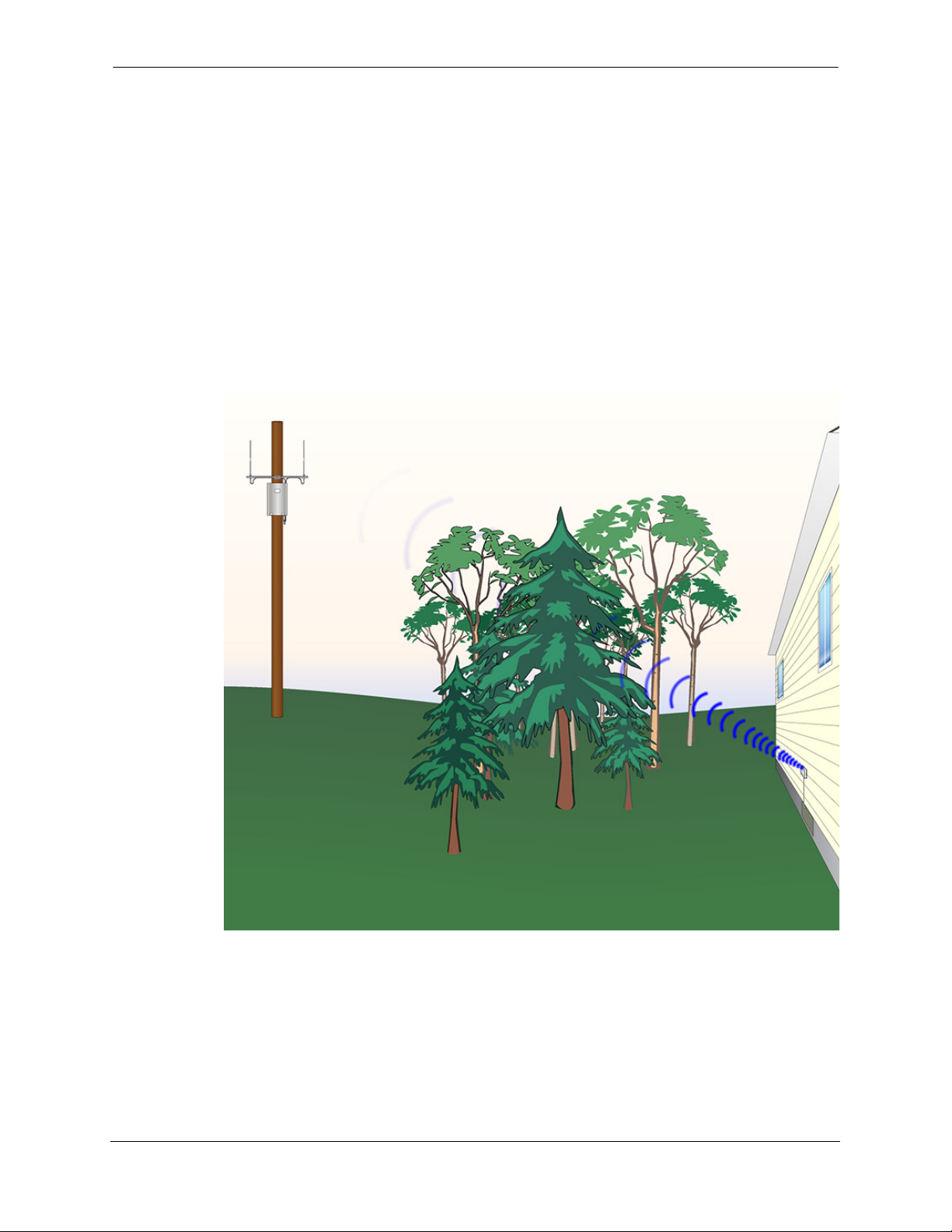
RF absorption occurs naturally with objects that are not electric conductive such as
drywall, concrete, wood, and foliage. A variety of factors affect how much RF
energy is absorbed by the obstruction. The following illustrates how concrete tends
to absorb more RF energy than a sheet of drywall.
4 MTU Installation Guidelines
Page 11

RF Reflection
RF reflection occurs when objects made of conductive materials (typically metal)
are in or near the transmission path. While reflection itself may not negatively
affect system performance, the RF signal may be reflected into an absorbing
material such as dense foliage or the concrete foundation of a building. Common
objects that reflect RF signals are metal buildings such as sheds or warehouses,
metal fences, HVAC ducts, vehicles, and metal signs. It is important to note that
even metal fences that are not solid (e.g. chain-link, wrought iron) will reflect ta
large portion of the RF signals.
Overview
MTU Installation Guidelines 5
Page 12

Signal Propagation
RF Shadowing
RF shadowing is a phenomenon related to absorption and reflection that occurs
when a transmitter is too close to another object. The image below illustrates how
the downspout, iron pipe, and the AC unit all shadow the RF signal.
6 MTU Installation Guidelines
Page 13

Overview
The signal is narrowest when it first leaves the MTU. The closer an object is to the
MTU, the greater the impact the object will have on the signal. This is illustrated in
the image below, where the close proximity of the garbage dumpster is blocking
the signal from the MTU.
Simply moving the dumpster several feet away from the MTU allows a greater
portion of the signal to propagate.
MTU Installation Guidelines 7
Page 14

Signal Propagation
8 MTU Installation Guidelines
Page 15

M
OUNTING
The following sections describe the nature of RF signal transmission in the UHF
frequency range, and specific factors to consider when installing an MTU on the
exterior of a building, inside a building, or in a meter pit. Regardless of the
installation environment, the MTU must be mounted securely.
Exterior Mounting
Issues with performance of exterior mounted MTUs are typically the result of
mounting the MTU too low, or mounting it in such a way that it is blocked by
various obstructions.
In the following real world example, the MTU is mounted between the protruding
exterior wall and the hose reel, both of which absorb the RF signal.
C
ONSIDERATIONS
Raising the MTU above the hose reel will reduce the amount of signal absorbed,
but a better solution is to move the MTU to the front of the building, as shown
below.
MTU Installation Guidelines 9
Page 16

Exterior Mounting
In this example, the RF signal is reflected off of the iron fence and absorbed by the
exterior wall of the home.
10 MTU Installation Guidelines
Page 17

Mounting Considerations
Simply raising the MTU above the fence and moving it to the end of the home (B)
will drastically reduce the amount of RF energy reflected by the fence and improve
system communication. The ideal location for the MTU, however, is on the front
of the home (A).
MTU Installation Guidelines 11
Page 18

Exterior Mounting
The image below illustrates how the hose reel, the meter, and the wall ledge all
shadow the RF signal.
Raising the MTU above the ledge and moving it to the edge of the building
eliminates the shadowing effect of the meter, ledge, and hose reel.
12 MTU Installation Guidelines
Page 19

Summary
Mounting Considerations
• Mount the MTU as high as possible. The MTU must be mounted at or above
grade (ground level).
• Mount the MTU with the Aclara logo facing the installer.
• Mount the MTU at least six inches away from any metal objects, including
pipes, conduit, and downspouts.
• Mount the MTU so that the top is at least one inch below the siding overlap.
• When mounting multiple MTUs in the same location, leave at least 4 inches
between the MTUs if mounting side by side, and at least 3 inches between
MTUs if mounting one above another.
• Do not mount the MTU so that it is transmitting towards a nearby building or
fence.
• Do not mount the MTU directly under AC power or telecommunications
wires.
MTU Installation Guidelines 13
Page 20

Interior
Interior
T
IP
MTUs installed inside of a building should be mounted on an exterior wall that is
not immediately facing a neighboring building. As with exterior installations, the
MTU should be mounted perpendicular to the ground with the Aclara logo facing
the installer.
Use a cellular phone’s signal strength indicator to gauge the amount of signal
interference within a building. Check the signal prior to entering the building,
and then again at the proposed mounting location. A drastic drop in cellular
signal reception may indicate potential problems with MTU transmission.
When mounting an MTU inside, it is important to note anything on the outside of
the wall that may cause interference, such as aluminum siding, or AC units.
The following illustration shows an incorrect MTU installation. The MTU is
mounted to the ceiling, facing the floor, and surrounded by copper and iron pipes.
In this case, the RF signal is not only directed towards the floor, but heavily
shadowed by the pipes.
The MTU should be mounted to the wall and away from the metal pipes, as shown
below.
14 MTU Installation Guidelines
Page 21

Mounting Considerations
Mount the MTU at least 5-10 feet away from large metal objects like furnaces,
duct work, refrigerators, and cabinets. In the example below, the MTU is mounted
between the HVAC duct and the refrigerator. Both of these large metal objects will
interfere with the RF signal.
MTU Installation Guidelines 15
Page 22

Interior
Moving the MTU several feet away from the duct and the refrigerator will
eliminate the interference and increase system performance considerably.
Summary
• Mount the MTU as high as possible near an exterior wall. The MTU must be
mounted at or above grade (ground level).
• Mount the MTU perpendicular to the ground with the Aclara logo facing the
installer.
• Mount the MTU at least six inches away from pipes and conduit.
• Mount the MTU so that the top is several inches below the ceiling.
• Mount the MTU at least five feet away from any large metal objects. (e.g.
refrigerators, HVAC ducts, furnaces, and hot water heaters)
• Do not mount the MTU in a basement with a metal ceiling.
• Do not
mount the MTU directly under AC power wires, circuit breaker
panels, or telecommunications wires.
16 MTU Installation Guidelines
Page 23

Pit
Mounting Considerations
MTUs connected to meters located in meter pits may be mounted to approved,
non-metallic pit lids. The MTUs should be mounted with the Aclara logo facing
the pit lid, as shown in the following image.
Pit lids that are ribbed on the underside require short spacers, while meter pit lids
that are smooth on the underside require long spacers. Short spacers are marked
with an S, and long spacers are marked with an L. Always use the appropriate
spacers when mounting an MTU to a meter pit lid.
MTU Installation Guidelines 17
Page 24

Pit
MTU to pit lid mounting procedures vary according to pit lid model. Please refer
to the appropriate pit lid installation instructions for specific mounting procedures.
Summary
• Mount the MTU to approved, non-metallic meter pit lids only.
• Mount the MTU with the label facing the pit lid.
• Use the appropriate spacers for the type of meter pit lid.
18 MTU Installation Guidelines
Page 25

W
IRING
All wiring must be consistent with the wiring provided with the MTU and adhere
to local and national codes.
Cable Insulation
Most MTUs are shipped with black cable insulation. Dual port MTUs, however
will have two cables: one with black insulation and one with gray insulation. The
black inulated cable is for port 1, and the gray insulated cable is for port 2.
Wire Length
MTUs are provided with a standard wire length of 12 feet. If necessary, additional
wire may be used to extend the range between the meter and the MTU up to 500
feet. (Some meters require shorter wire lengths. Please refer to the meter
manufacturer’s documentation for exact limitations.) Always use cable of with 22
AWG solid copper wire, preferably with similar insulation coloring when
extending the wiring.
Wire Routing
All wiring should be secured every 18 inches and before and after every change in
direction. Wiring routed along wood or drywall should be secured with 9/16"
rounded-crown staples. Wiring routed along masonry walls should be secured
using appropriate wire clips. The MTU cable should be allowed to move slightly
within the staples or wire clips.
All changes in wire direction should only be made at right angles. Wiring should
run parallel to ceiling joists, when possible. If joists must be crossed, the wiring
should cross the joists at right angles.
If wire clearance holes are needed to route wire from the meter to the MTU, use a
¼" drill bit. The installer is responsible for the selection of an appropriate location
for any hole to be drilled.
MTU Installation Guidelines 19
Page 26

Connections
Connections
All connections must be made using silicone gel filled IDCs. Typical splice
connectors will require removing approximately 1" of the outer cable jacket.
C
AUTION
Interior/Exterior Environment
It is important that you do not damage the insulation of the inner conductors
when removing the outer jacket.
Aclara recommends you refer to the specific manufacturer for detailed installation
instructions. The connectors must be installed according to the manufacturer’s
instructions.
Please consult the appropriate meter installation instructions for specific MTU
wiring instructions.
All wire connections outside the building must be made with UL and RUS listed
moisture and solvent resistant connectors. These are silicone gel filled, electrical
insulating, IDCs.
Meter Pit Environment
All wire connections that are in a pit environment must be made using the
appropriate IDCs with a silicone electrical insulating gel. The connectors must be
UL listed as a wire connector system for use with underground conductors and
CSA certified as a underground cable splicing kit for 600V direct bury and
submersion applications.
20 MTU Installation Guidelines
Page 27

CHAPTER 0APPENDIX
A
C
HAPTER
0
R
ECOMMENDED
This appendix provides a detailed list of recommended tools and supplies for specific installation
types.
Tools Indoor Outdoor Pit
Hammer XXX
Staple gun X X
Flashlight X X X
Diagonal cutters X X X
Wire stripper X X X
Flat-tip screwdriver X X X
Phillips head screwdriver X X X
Cordless drill/driver with flat and phillips bits X X X
1/4" General purpose/twist drill bit, standard length X X
1/4" x 12" General purpose/twist drill bit X
Cellular phone X X X
Connector crimping tool X X X
Fine-point permanent marker X X X
Safety glasses X X X
Spare serial adapter batteries (AA) X X X
Known good meter register X X X
Known good MTU X X X
E
QUIPMENT
Supplies Indoor Outdoor Pit
Cable ties X X X
9/16" Rounded-crown staples X
#6 x 1" Plastic anchors for screws X X
#6 x 1 5/8" Drywall screws X
#8 x 1 3/4" Exterior grade screws X
RTV silicone sealant X X
Electrical tape X X
3 Conductor, 22 AWG, solid copper wire w/black jacket X X
3 Conductor, 22 AWG, solid copper wire w/gray jacket X X
Gel-filled, insulation displacement connectors (Aclara #043-1913,
or equivalent)
Direct burial splice kits (Aclara #043-1912, or equivalent) X
Short MTU spacers (Aclara #056-8150S) X
Long MTU spacers (Aclara #056-8150L) X
XXX
Page 28

22 MTU Installation Guidelines
Page 29

CHAPTER 0APPENDIX
B
C
HAPTER
Use the following checklists to help verify the correct installation of MTUs.
General
Is the MTU mounted securely?
Is it mounted perpendicular to the ground with the Aclara logo facing
you?
Is there a minimum of 1 inch clearance above the MTU?
If mounting multiple MTUs side by side, is there at least 4 inches between
them?
If mounting multiple MTUs above one another, is there at least 3 inches
between them?
Is there minimum of 6 inches of clearance between the MTU and any
pipes, conduit, downspouts, etc.?
Is there a minimum of 5 feet of clearance between the MTU and any
large metal objects, such as dumpsters, HVAC ducts, or cabinets?
Is there any damage to the wiring (e.g. nicks or cuts)?
Exterior
Is the MTU mounted at least 12 inches above the ground?
Is the MTU mounted so that it is not transmitting directly into a metal
fence?
Are wire splices made using silicone electrical gel filled IDCs?
Interior
Is the MTU mounted in a room without a metal ceiling?
Is the MTU mounted near an exterior wall?
If located in a basement, is the MTU mounted as high as possible?
Meter Pit
Is the MTU mounted securely to a non-metallic lid?
Is the MTU mounted with the Aclara logo facing the lid?
Are wire splices made using silicone gel filled electrical insulating IDCs
and appropriate direct burial kit?
If necessary, is the MTU mounted with the appropriate spacers?
0
C
HECKLIST
Page 30

 Loading...