

Page 1

Series 4000 MTU
DRAFT
Maintenance
and Operation
Manual
Y20456-TUM
Rev. A
www.Aclara.com
Page 2

DRAFT
Page 3

Proprietary Notice
DRAFT
Information contained in this document is private to Aclara Technologies LLC, an Ohio limited
liability company (Aclara). This information may not be published, reproduced, or otherwise
disseminated without the express written authorization of Aclara.
Any software or firmware described in this document is furnished under a license and may be
used or copied only in accordance with the terms of such license.
Disclaimer
The information in this document is subject to change without notice and should not be construed
as a commitment by Aclara. Aclara assumes no responsibility for any errors that may appear in
this document.
No responsibility is assumed for the use or reliability of software on equipment that is not
supplied by Aclara.
TWACS, STAR, and Metrum Cellular are registered trademarks of Aclara Technologies LLC.
Aclara Technologies LLC
Confidential and Proprietary
Copyright 2015. All Rights Reserved.
Series 4000 Maintenance and Operations Manual (Y20456-TUM Rev A)
Page 4

DRAFT
Page 5

WARNINGS, CAUTIONS, AND NOTES
DRAFT
Always consult and adhere to all local and national safety codes, regulations, and
standards.WARNING, CAUTION and Note statements are used throughout this
manual to emphasize important and critical information to help you ensure safety
and prevent product damage.These statements are defined below.
WARNING
CAUTION
NOTE
indicates a potentially hazardous situation which, if not avoided, could result in
death or serious physical injury.
indicates a situation, which, if not avoided, could result in damage to
equipment, damage to software, loss of data or invalid results.
indicates important supplemental information.
FCC/IC Compliance
The following statements cover the RF exposure guide and the field calibration
procedure.
FCC/IC RF Exposure Guide
Field Calibration Procedure
Series 4000 Maintenance and Operations Manual iii
Aclara Technologies LLC low power RF devices and their antennas must be
fixed-mounted on indoor or outdoor permanent structure(s) providing a separation
distance of at least 20 cm from all persons during normal operation. This device is
not designed (and it has no external connection) to operate in conjunction with any
other antennas or transmitters. No other operating instructions for satisfying RF
exposure compliance are needed.
Aclara Technologies LLC low power RF devices have passed through extensive
testing and calibration procedures while in the factory. Therefore, no additional
calibration or adjustment is required in the field.
Page 6

Conformité FCC/IC
DRAFT
AVERTISSEMENTS, MISES EN GARDE ET REMARQUES
Toujours consulter et respecter les codes, règlements et normes de sécurité locaux
et nationaux. Des AVERTISSEMENTS, MISES EN GARDE et remarques sont
utilisés tout au long de ce guide pour souligner l'information importante et critique
qui vous aidera à assurer la sécurité et à prévenir les dommages au produit. Ces
énoncés sont définis ci-dessous.
AVERTISSEMENT
indique une situation potentiellement dangereuse qui, si elle n'était pas évitée,
pourrait entraîner la mort ou des blessures graves.
MISE EN GARDE
indique une situation qui, si elle n'était pas évitée, pourrait entraîner des
dommages à l'équipement, des dommages au logiciel, des pertes de données ou
des résultats invalides.
REMARQUE
indique des informations supplémentaires importantes.
Conformité FCC/IC
Les énoncés qui suivent portent sur le guide d'exposition aux RF et la procédure de
calibration sur place.
Guide d'exposition aux RF FCC/IC
Les appareils RF à faible puissance Aclara Technologies LLC ainsi que leurs
antennes doivent être montés de manière fixe sur des structures intérieures ou
extérieures permanentes qui se trouvent à au moins 20 cm des personnes pendant
le fonctionnement normal. Cet appareil n'est pas conçu (et il n'a aucun
branchement externe) pour être utilisé en association avec toute autre antenne ou
tout transmetteur. Aucune autre instruction d'utilisation n'est requise pour assurer
la conformité aux règles d'exposition aux RF.
Procédure de calibration sur place
Les appareils RF à faible puissance Aclara Technologies LLC ont été soumis à des
tests étendus et multi-tâches et à des procédures de calibration complexes en usine.
Par conséquent, ils ne requièrent pas de calibration ni d'ajustement supplémentaire
sur place. Les appareils RF à faible puissance Aclara Technologies LLC sont
expédiés au client dans des boîtiers scellés. Aucun ajustement ne peut donc être
effectué sur place sans briser le boîtier scellé en usine.
iv Series 4000 Maintenance and Operations Manual
Page 7

Table of Contents
DRAFT
Chapter 1: STAR Network Overview 1
Two-Way Communications. . . . . . . . . . . . . . . . . . . . . . . . . . . . . . . 1
MTU/DCU Communications. . . . . . . . . . . . . . . . . . . . . . . . . . . . . . 1
DCU/NCC Communications. . . . . . . . . . . . . . . . . . . . . . . . . . . . . . 1
Chapter 2: Series 4000 Operation 3
Configuration . . . . . . . . . . . . . . . . . . . . . . . . . . . . . . . . . . . . 3
Read Intervals . . . . . . . . . . . . . . . . . . . . . . . . . . . . . . . . . . . . 3
Time Synchronization. . . . . . . . . . . . . . . . . . . . . . . . . . . . . . . . . 3
Security . . . . . . . . . . . . . . . . . . . . . . . . . . . . . . . . . . . . . . . 4
Hardware . . . . . . . . . . . . . . . . . . . . . . . . . . . . . . . . . . . . . 4
Software . . . . . . . . . . . . . . . . . . . . . . . . . . . . . . . . . . . . . . 4
Alarms . . . . . . . . . . . . . . . . . . . . . . . . . . . . . . . . . . . . . . . 5
Data Encryption . . . . . . . . . . . . . . . . . . . . . . . . . . . . . . . . . . . 5
Trend Mode . . . . . . . . . . . . . . . . . . . . . . . . . . . . . . . . . . . . . 5
Read Interval . . . . . . . . . . . . . . . . . . . . . . . . . . . . . . . . . . . . 5
Transmit Interval . . . . . . . . . . . . . . . . . . . . . . . . . . . . . . . . . . 6
Chapter 3: STAR Programmer Software 7
USB Port. . . . . . . . . . . . . . . . . . . . . . . . . . . . . . . . . . . . . . . 7
Communication LEDs. . . . . . . . . . . . . . . . . . . . . . . . . . . . . . . . . 8
Software . . . . . . . . . . . . . . . . . . . . . . . . . . . . . . . . . . . . . . 9
Prerequisites . . . . . . . . . . . . . . . . . . . . . . . . . . . . . . . . . . . . 9
Application Installation . . . . . . . . . . . . . . . . . . . . . . . . . . . . . . 10
XML File Installation. . . . . . . . . . . . . . . . . . . . . . . . . . . . . . . . 13
Connection . . . . . . . . . . . . . . . . . . . . . . . . . . . . . . . . . . . . 16
Operation . . . . . . . . . . . . . . . . . . . . . . . . . . . . . . . . . . . . 17
Read MTU . . . . . . . . . . . . . . . . . . . . . . . . . . . . . . . . . . . 17
Turn Off MTU . . . . . . . . . . . . . . . . . . . . . . . . . . . . . . . . . . 17
Add MTU . . . . . . . . . . . . . . . . . . . . . . . . . . . . . . . . . . . . 18
Replace MTU . . . . . . . . . . . . . . . . . . . . . . . . . . . . . . . . . . 20
Install Confirmation. . . . . . . . . . . . . . . . . . . . . . . . . . . . . . . 22
Replace Battery . . . . . . . . . . . . . . . . . . . . . . . . . . . . . . . . 22
Chapter 4: Hardware Installation 23
Wall Mount . . . . . . . . . . . . . . . . . . . . . . . . . . . . . . . . . . . . 23
Solid Wall . . . . . . . . . . . . . . . . . . . . . . . . . . . . . . . . . . . . 24
Hollow Wall . . . . . . . . . . . . . . . . . . . . . . . . . . . . . . . . . . . 25
Pipe Mount . . . . . . . . . . . . . . . . . . . . . . . . . . . . . . . . . . . . 27
Wiring. . . . . . . . . . . . . . . . . . . . . . . . . . . . . . . . . . . . . . . 29
Conduit & Fittings. . . . . . . . . . . . . . . . . . . . . . . . . . . . . . . . . 30
MTU Connections . . . . . . . . . . . . . . . . . . . . . . . . . . . . . . . . . 31
Instrument Connections . . . . . . . . . . . . . . . . . . . . . . . . . . . . . . 32
Commissioning. . . . . . . . . . . . . . . . . . . . . . . . . . . . . . . . . . . 33
Chapter 5: Maintenance 35
Series 4000 Maintenance and Operations Manual v
Page 8

DRAFT
Page 9

STAR NETWORK OVERVIEW
DRAFT
The STAR Network is a fixed-network, Advanced Metering Infrastructure (AMI)
that automatically reads water and gas instruments. The STAR Network uses a
3-tier configuration to read and transmit information between the measuring
instrument and the utility office. The three tiers of the STAR Network are:
1. Meter Transmission Units (MTUs)
2. Data Collection Units (DCUs)
3. Network Control Computer (NCC)
Two-Way Communications
The STAR Network two-way advanced metering infrastructure (AMI) system
allows encrypted data communications over secure, FCC licensed radio
frequencies. This wireless fixed network consists of the Meter Transmitter Unit
(MTU), Data Collector Unit (DCU), and Network Control Computer (NCC).
Communications between the MTU, DCU, and NCC are explained in greater
detail below.
MTU/DCU Communications
DCU/NCC Communications
Series 4000 Maintenance and Operations Manual 1
MTU/DCU communications occur on two FCC licensed (450-470 MHz)
frequency channels. Configuration settings, on-demand requests, and Time Sync
messages are sent from the DCU to the MTU. Instrument measurement and
configuration readings and Time Sync requests are sent from the MTU to nearby
DCUs.
DCU/NCC communications are conducted over TCP/IP protocols via the cellular,
Ethernet, or Wi-Fi
with the NCC. Configuration changes, on-demand requests, and Time Sync
messages originate in the NCC and are sent to the MTU via the DCU.
™
backhaul. The DCU initiates and maintains communications
Page 10

Two-Way Communications
DRAFT
2 Series 4000 Maintenance and Operations Manual
Page 11

SERIES 4000 OPERATION
DRAFT
The Series 4000 MTU is designed to connect with a Honeywell ERX pressure
monitor, a Honeywell Mini-AT volume corrector, or a Mini-Max volume
corrector. In addition to a 10 item audit trail, the Series 4000 allows the user to
perform on-demand reads and reconfigure the instrument and the MTU via the
NCC. It contains a replaceable battery, two LEDs, and a USB port used for
commissioning and reading information from the MTU locally.
The Series 4000 MTU is mounted to a wall or a pipe near the volume corrector or
pressure monitor. The MTU connects to the instrument via cable and
communicates with the DCU using FCC licensed frequencies.
Configuration
The Series 4000 MTU allows the user to change instrument configuration settings
from the NCC. The MTU checks the instrument configuration daily, and returns
the changed parameter and the new value to the NCC in a daily Change Report.
The NCC will then compare the Change Report data to the initial configuration
value transmitted to the NCC immediately after installation. In addition to these
Change Reports, the user can also configure the MTU to send a full Configuration
Report to the NCC every 30, 60, 90, or 180 days.
For added security, if there is an attempt to change the configuration settings
through the MTU USB port, the MTU will notify the NCC within 25 hours.
Read Intervals
The rate at which the MTU reads data from the instrument is configurable to
support instrument log intervals of 15 minutes or more. At the end of each interval,
the MTU will read the instrument. The data will then be transmitted back to the
NCC at an interval that is equal to the instrument log interval.
Time Synchronization
Time keeping is crucial for accurate reporting. The Series 4000 MTU and the NCC
software are designed to ensure that the internal clocks of the instrument, MTU,
and NCC all remain synchronized. In addition to synchronizing the time at initial
installation, the MTU checks the instrument clock daily. If the clock is off by more
than 10 seconds, it will automatically synchronize the instrument clock.
The MTU will send a flag to the NCC along with the amount of adjustment made
to the instrument clock for any readings that are off by more than two minutes.
When the NCC receives readings that are flagged with incorrect time, it will
automatically correct the time stamps according to the difference reported by the
MTU.
MTU Installation Requirements 3
Page 12

Security
DRAFT
Security
Hardware
The 4000 Series MTU provides options for both hardware and software security.
The Series 4000 MTU enclosure is designed to allow the user to secure the door
with a lockout device.
Software
The MTU may be configured to send the following tamper alarms to the NCC:
1. Interface tamper (configuration change via USB port)
2. Cut serial communication wire
Each tamper condition generates a corresponding alarm transmission that can be
viewed in the NCC when viewing the Premise transmissions.
The MTU can be programmed to transmit an alarm for any of these tamper
conditions. In the case of a tamper condition alarm, the unit will transmit an alarm
message every minute for a given number of times (with a default of 3). When the
tamper condition is no longer present, the alarm flag is cleared. Each time the
tamper condition is detected, the unit will trigger an alarm.
4 MTU Installation Requirements
Page 13

Alarms
DRAFT
In addition to the tamper alarms, the MTU may also be configured to send the
following alarms to the NCC:
Last Gasp
The MTU will regularly report battery voltage values to the NCC. When this value
falls below a specified value, the NCC will display a Low Battery notification.
Aclara recommends changing the battery promptly when a low battery alarm is
received. Please see Maintenance on page 35 for more information.
Pressure
The user can configure the MTU to return a pressure alarm whenever the pressure
reading from the instrument is outside a given range. If enabled, the MTU will also
begin operating in Trend Mode until the pressure returns to the desired range.
Please refer to Trend Mode on page 5 for more information.
Serial Communication Problems
Series 4000 Operation
The MTU will return an alarm to the NCC if basic communication with the
instrument is not possible. This will most likely be due to incorrect instrument
configuration.
Data Encryption
The Series 4000 MTU units support the encryption of user sensitive data. When
data encryption is enabled, all readings and data packets except for alarms will be
encrypted prior to transmission.
Trend Mode
Trend Mode is an operating mode of the MTU that, when enabled, will begin
automatically sending pressure values (and corresponding time stamps) at regular
intervals whenever a pressure or other configured alarm is received from the
instrument.
Trend Mode may also be initiated or canceled directly from the NCC. Using the
default settings for Trend Mode, the MTU will record the pressure once a minute
and transmit these readings once every six minutes to the NCC.
Read Interval
MTU Installation Requirements 5
The user may configure Trend Mode to read the pressure either once a minute or
once every five minutes.
Page 14

Trend Mode
DRAFT
Transmit Interval
The transmit interval for Trend Mode is pre-configured at six times the read
interval. That is:
• If a 1 minute read interval is selected, the transmit interval will be 6 minutes.
• If a 5 minute read interval is selected, the transmit interval will be 30 minutes.
If Trend Mode is canceled from the NCC or if the MTU receives a clear pressure
alarm signal from the instrument, the MTU will notify the NCC that only six more
readings will be received in Trend Mode. The MTU will read and transmit the
remaining Trend Mode reads, before it switches back to normal operating mode.
If Trend Mode is initiated manually via the NCC, it will continue for a maximum
of 30 minutes if it is not manually canceled from the NCC.
Trend Mode data is recorded and stored along with graphical representations in the
NCC for up to 13 months.
6 MTU Installation Requirements
Page 15

STAR PROGRAMMER SOFTWARE
DRAFT
The STAR Programmer application is used along with a suitable tablet or laptop and a USB cable
(Aclara part number 070-1700) to commission an MTU after installation or to turn an MTU off
prior to storage or relocation. This section provides information on the USB communication
interface and how to interact with the MTU using this application.
USB Port
The Series 4000 MTU uses a standard USB Type B port that allows for communication with a
laptop or tablet running the STAR Programmer software.
WARNING: EXPLOSION HAZARD - BATTERIES MUST ONLY BE CHANGED IN AN AREA KNOWN TO
AVERTISSEMENT:
Series 4000 Maintenance and Operations Manual 7
BE NON-HAZARDOUS
RISQUE D'EXPLOSION
L’EMPLACEMENT EST DÉSIGNÉ NON DANGEREUX AVANT DE CHANGER LA BATTERIE.
- AFIN D’ÉVITER OUT RISQU D’EXPLOSION, S’ASURER QUE
Page 16

USB Port
DRAFT
Communication LEDs.
Two LEDs located to the right of the battery and above the COMP1 connector indicate the
direction of communication through the USB port.
• The left LED (LED 1) indicates when data is sent from the tablet or laptop through the USB
port to the Series 4000 MTU.
• The right LED (LED2) indicates when data is sent from the MTU out through the USB port
to the tablet or laptop.
8 Series 4000 Maintenance and Operations Manual
Page 17

STAR Programmer Software
DRAFT
Software
The STAR Programmer application may be used to commission an MTU after installation, read
and troubleshoot an MTU in the field, or to turn off an MTU if it will not be in use for an extended
period of time. Actions performed using the STAR Programmer software are logged and
uploaded to the Network Control Computer (NCC) for verification at the end of each shift.
Prerequisites
The STAR Programmer application requires the following to communicate with a Series 4000
MTU:
Tablet or laptop with
• Windows® 7
• > 1.5 GHz
• > 2 GB RAM
• > 80 GB HDD
• Open USB port
USB-A to USB-B cable (Aclara #070-1700)
Series 4000 Maintenance and Operations Manual 9
Page 18

Software
DRAFT
Application Installation
Use the following procedure to install the STAR Programmer software on a suitable tablet or
laptop.
1) Double-click the STARProgrammerPC.msi file.
2) Click Next to begin the STAR Programmer Setup Wizard.
10 Series 4000 Maintenance and Operations Manual
Page 19

3) Verify the installation location, and click Next.
DRAFT
STAR Programmer Software
4) Click Next to initiate the installation.
Series 4000 Maintenance and Operations Manual 11
Page 20

Software
DRAFT
5) Wait while the STAR Programmer is installed.
6) Click Close after the Installation Complete confirmation appears.
12 Series 4000 Maintenance and Operations Manual
Page 21

STAR Programmer Software
DRAFT
XML File Installation
Use the following procedure to install the XML files that accompany the STAR Programmer
application.
1) Refer to the table below when selecting the appropriate STARXML.msi file for the
installation.
N
OTE: Multiple STARXML installations cannot coexist on the same machine.
Installation Type .MSI File
PC Interactive Mode - With Encryption STARXMLPCTEST.msi
PC Interactive Mode - Without Encryption STARXMLPCTESTNONENCRYPT.msi
PC Scripted Mode STARXMLPC.msi
2) Double-click the appropriate .msi file.
3) Click Next to begin the XML File Setup Wizard.
Series 4000 Maintenance and Operations Manual 13
Page 22

Software
DRAFT
4) Verify the installation location, and click Next.
5) Click Next to initiate the installation.
14 Series 4000 Maintenance and Operations Manual
Page 23

6) Wait while the XML files are installed.
DRAFT
STAR Programmer Software
7) Click Close after the Installation Complete confirmation appears.
Series 4000 Maintenance and Operations Manual 15
Page 24

Software
DRAFT
Connection
Use the following procedure to connect a tablet or laptop to a Series 4000 MTU and open the
STAR Programmer application.
1) Remove any security hardware from the
MTU door.
2) Open the door of the MTU.
4) Connect the remaining end of the USB
cable to the Series 4000 MTU.
5) Open the STAR Programmer application.
3) Connect the USB cable to the laptop or
tablet.
6) Leave the Operator and Password fields
blank and click
16 Series 4000 Maintenance and Operations Manual
Submit.
Page 25

STAR Programmer Software
DRAFT
Operation
The STAR Programmer menu functions for Series 4000 MTUs are Read MTU, Turn Off MTU,
Add MTU, Install Confirmation, and Replace Battery. Each of these functions are described in the
following sections.
Read MTU
This option allows the user to read information
from the MTU and the instrument. It will also
write configuration settings to the instrument.
Select this option to see the current MTU
settings or after changing a battery that has
completely lost power. When the user selects
the Read MTU option:
1) Select Read MTU.
2) Wait while the STAR Programmer reads
the MTU.
3) After viewing the MTU information screen,
select
the Main Menu.
OK to log the activity and return to
not
Turn Off MTU
This option allows the user to deactivate and
turn off a previously commissioned MTU.
When a Series 4000 MTU has been turned off,
the STAR Programmer software will read the
MTU Type, firmware version, and MTU ID
before turning off the MTU. The MTU will
cease all RF transmission and will only
respond to commands sent through the USB
port.
1) Select Turn Off MTU.
2) Wait while the application reads and turns
off the MTU.
3) Click OK to log the activity and return to the
Main Menu.
Series 4000 Maintenance and Operations Manual 17
Page 26

Software
DRAFT
Add MTU
Select this option to commission a new MTU
or an MTU that was turned off.
1) Select Add MTU.
3) Enter the 10-digit Account Number into the
Gas Network Node (
4) Verify the Instrument Type field has
auto-populated, and click
GNN) field.
OK.
2) Click OK to read the MTU and instrument.
5) Wait while the software commissions the
MTU. This may take several minutes.
18 Series 4000 Maintenance and Operations Manual
Page 27

STAR Programmer Software
DRAFT
6) Once commissioning is complete, the
software will return the current values
allowing you to confirm the settings.
7) Click OK to confirm the log entry and return
to the Main Menu.
8) To close the STAR Programmer application,
select File > Exit.
Series 4000 Maintenance and Operations Manual 19
Page 28

Software
DRAFT
Replace MTU
To replace an existing MTU or after installing
a new battery in an MTU that has been without
power for an extended amount of time, use the
Replace MTU option in the STAR
Programmer application.
1) Select Replace MTU.
3) Enter the 10-digit Account Number into the
Gas Network Node (
4) Verify the Instrument Type field has
auto-populated, and click
GNN) field.
OK.
2) Click OK to read the MTU and instrument.
5) Wait while the software commissions the
MTU. This may take several minutes.
20 Series 4000 Maintenance and Operations Manual
Page 29

STAR Programmer Software
DRAFT
6) Once commissioning is complete, the
software will return the current values
allowing you to confirm the settings.
7) Click OK to confirm the log entry and return
to the Main Menu.
8) To close the STAR Programmer application,
select File > Exit.
Series 4000 Maintenance and Operations Manual 21
Page 30

Software
DRAFT
Install Confirmation
This option allows the user to confirm that the
MTU can communicate with the available
DCUs and to see information about the MTU,
DCU, and the communication between the
two.
1) Select Install Confirmation.
Replace Battery
Use the following procedure after replacing the
battery in the MTU.
1) Select Replace Battery.
2) Click OK to initiate the confirmation
process.
3) Wait while the STAR Programmer reads
the MTU.
4) After viewing the MTU information screen,
select
the Main Menu.
OK to log the activity and return to
2) Click the OK button to initiate the process.
3) Wait while the STAR Programmer reads
the MTU.
4) Click OK to log the activity and return to the
Main Menu.
22 Series 4000 Maintenance and Operations Manual
Page 31

HARDWARE INSTALLATION
DRAFT
Aclara offers kits to mount the Series 4000 MTU to a wall or to a pipe with an outside diameter of
2
"- 3". Use the corresponding instructions to mount a Series 4000 MTU using one of these kits.
NOTE In addition to the mounting hardware, the installation kits also include one 10' length of
conduit, two conduit fittings, one 12' length of five conductor cable, and one 12’ length of
two conductor cable. Please refer to the Wiring section on page 29 for installation procedures
for these items.
Wall Mount
Wall Kit #109-2015-001M-020
Item Description Application Quantity
A ¼ x 2" Stainless steel wedge bolt Solid walls 4
B ¼" Stainless steel flat washer Solid and hollow walls 4
C ¼ - 20 x 2½" Stainless steel bolt Hollow walls 4
D Wall anchor Hollow walls 4
Series 4000 Maintenance and Operations Manual 23
Page 32

Wall Mount
DRAFT
Solid Wall
Follow this procedure to mount the MTU to a
solid wall.
Special Tools
In addition to standard tools and safety
equipment, you will need the following tools to
mount the MTU to a solid wall:
• Drill
• ¼" Wedge drill bit
• 0-35 ft-lb Torque-limiting wrench
Instructions
1) Determine the appropriate mounting
location for the MTU. Keep RF signal
propagation in mind when choosing a
location.
2) Position the MTU against the wall at the
desired location and mark locations for the
four bolt holes.
3) Drill holes at the four marked locations
with a ¼" Wedge Bit.
4) Insert a wedge bolt through a flat washer
and one of the mounting holes on the MTU.
5) Thread the bolt partially into the
appropriate hole drilled in step 3.
24 Series 4000 Maintenance and Operations Manual
6) Repeat steps 4 and 5 for the remaining
bolts.
7) Tighten all four wedge bolts to 27-33 ft-lb.
Page 33

Hardware Installation
DRAFT
Hollow Wall
Follow this procedure to mount the MTU to a
hollow wall.
Special Tools
In addition to standard hand tools and safety
equipment, you will need the following tools to
mount the MTU to a hollow wall:
• Drill
• ½" Drill bit
• 0-10 ft-lb Torque-limiting wrench
Instructions
1) Determine the appropriate mounting
location for the MTU. Keep RF signal
propagation in mind when choosing the
location.
2) Position the MTU against the wall at the
desired location and mark locations for the
four bolt holes.
3) Drill holes at the four marked locations
with a ½" drill bit.
4) Insert the anchor end of one wall anchor
through one of the drilled holes.
Series 4000 Maintenance and Operations Manual 25
5) Pull the anchor until it is tight against the
back side of the wall surface. Then slide the
cap forward until it is flush with the wall.
Page 34

Wall Mount
DRAFT
6) Snap off the excess strap by pressing the
top strap up and the bottom strap down.
7) Repeat Steps 4-6 for the three remaining
anchors.
8) Place a flat washer on each of the bolts, and
insert the bolts through the mounting holes
of the MTU.
9) Thread each bolt into the appropriate
anchor.
10) Tighten each bolt to 5-7 ft. lbs.
26 Series 4000 Maintenance and Operations Manual
Page 35

Pipe Mount
DRAFT
Hardware Installation
Pipe Mount Kit #109-2015-001M-21
Item Description Quantity
A
B
Series 4000 Maintenance and Operations Manual 27
Bracket assembly (
2 "- 3" Screw-drive tube clamp
5
/16
"-18 bolt, metal washer, nylon washer, & bracket)
2
2
Page 36

Pipe Mount
DRAFT
Special Tools
In addition to standard hand tools and safety
equipment, the Pipe Mounting kit also requires
the following:
• 0-20 ft-lb Torque-limiting wrench
• 0-10 in-lb Torque-limiting wrench or
screwdriver
1) Thread one of the clamps through both slots
in one of the brackets and around the pipe.
4) There are three mounting holes at the top of
the MTU and three at the bottom.
• If mounting to a Horizontal pipe, use the
top left and top right mounting holes.
• If mounting to a Vertical pipe, use the top
center and bottom center mounting holes.
2) Rotate the bracket to the desired mounting
position and tighten the clamp just enough
to maintain bracket position.
3) Thread the remaining clamp through the
remaining bracket and around the pipe.
5) Insert one of the bolts through a metal
washer, the appropriate MTU mounting
hole, and a nylon washer before threading it
into the bracket.
6) Repeat step 5 with the remaining hardware
to secure MTU to the remaining bracket.
7) Tighten both clamp screws to 7-9 in-lb.
28 Series 4000 Maintenance and Operations Manual
8) Tighten both bracket bolts to 14-16 ft-lb.
Page 37

Hardware Installation
DRAFT
Wiring
Use the following instructions to connect the MTU to a Honeywell electronic pressure monitor or
volume corrector.
Item Description Quantity
A 10' Conduit (Included in mounting kit) 1
B ½" Conduit fitting (Included in mounting kit) 2
C 12' Five conductor cable (Included in mounting kit) 1
D Five pin mating terminal (Included with MTU) 1
E Two pin mating terminal (Included with MTU) 1
F 12’ Two conductor cable (Included in mounting kit) 1
NOTE: This equipment provides non-incendive field wiring outputs for Class I, Division 2,
Group D.
Series 4000 Maintenance and Operations Manual 29
Page 38

Wiring
DRAFT
Conduit & Fittings
The cable connecting the MTU to the
instrument must be routed through the included
conduit. Use the following procedure to install
the conduit.
1) Remove the nut, sealing ring, and ferrule
from one of the conduit fittings.
2) Slide the nut and sealing ring over the end
of the conduit.
3) Insert the ferrule into the end of the conduit.
4) Thread the fitting body over the ferrule and
secure by tightening the gland nut. Tighten
the nut to 28-32 in-lb.
5) Repeat steps 1-4 to secure the remaining
fitting to the other end of the conduit.
8) Secure the fitting to the MTU with the lock
ring. Tighten the ring to 15-19 in-lb.
9) Route the conduit to the instrument.
CAUTION
10) Remove the lock ring from the remaining
Do not bend the conduit smaller than
a 3" radius.
conduit fitting and insert the fitting body
into an available opening in the pressure
monitor or volume corrector enclosure.
11) Secure the fitting to the instrument
enclosure with the lock ring. Tighten the
ring to 15-19 in-lb.
6) Remove a weather seal plug from the
bottom of the MTU enclosure.
7) Remove the lock ring from one of the
conduit fittings and insert the fitting body
into the opening in the bottom of the MTU.
30 Series 4000 Maintenance and Operations Manual
Page 39
MTU Connections
DRAFT
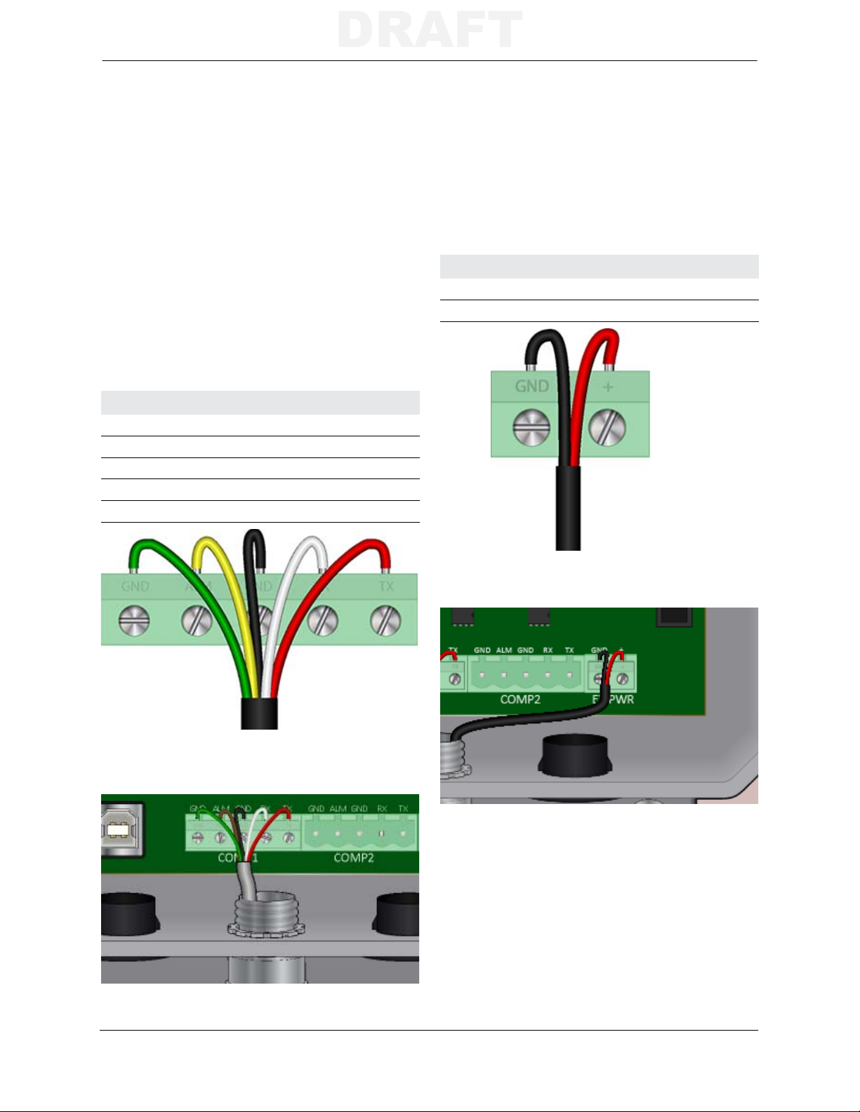
Use the following information when connecting the cables to the MTU.
Hardware Installation
1) Route the cable through the conduit.
2) Use the following information to connect
the cable wires to the MTU mating
connector. Secure each wire into the
connector by tightening the corresponding
set screw.
Comp1
1) Use the five conductor cable to connect the
communication terminals on the MTU with
the instrument.
MTU Connector Wire
GND (Ground) Green
ALM (Alarm) Yellow
GND (Ground) Black
TX (MTU Transmission) White
RX (MTU Reception) Red
Optional Power
1) Use the two conductor cable to connect the
MTU to an instrument supplied 10-15 VDC
power source.
MTU Connector Wire
GND (10-15 VDC ground) Black
+ (10-15 VDC positive) Red
2) Plug the MTU mating connector into the
COMP1 receptacle.
2) Plug the MTU mating connector into the
EX PWR receptacle.
Series 4000 Maintenance and Operations Manual 31
Page 40

Wiring
DRAFT
Instrument Connections
Use the information for the appropriate meter type to connect the MTU cable(s) to the instrument.
Refer to the Electrical Connection Parameters table for electrical parameters of each connector.
Mini-Max or ERX
Use the following information to connect the
MTU cable to a Honeywell Mini-Max volume
corrector or ERX pressure monitor.
COMP1
Mini-AT
Use the following information to connect the
MTU cable to the TB2 connector on a
Honeywell Mini-AT volume corrector.
COMP1
MTU Wire Mini-Max or ERX
GND Green
ALM Yellow
GND Black
TX White
RX Red
External Power (Optional)
TB1 A- (Ground)
TB1 A+ (Alarm)
Serial I/O GND (Ground)
Serial I/O RX (Receive)
Serial I/O TX (Transmit)
MTU Wire Mini-AT
GND Green A- (Ground)
ALM Yellow A+ (Alarm)
GND Black Com (Ground)
TX White RX (Receive)
RX Red TX (Transmit)
Connect the red (positive) and black (ground) wires from the MTU to an appropriate 10-15 VDC
auxiliary power source on the instrument. Please refer to specific instrument documentation for
detailed information.
Electrical Connection Parameters
COMP1 & COMP2 (J6 & J7) Input Output External Power (J12) Input
Ui = 12 V Uo = 3.5 V Ui = 15 V
Ii = 4 mA Io = 60 mA Ii = 45 mA
Pi = 50 mW Po = 210 mW Pi = 675 mW
Ci = 250 pF Co = 0 pF
Li = 0 Lo = 0
32 Series 4000 Maintenance and Operations Manual
Page 41

Hardware Installation
DRAFT
Commissioning
After installing and connecting the MTU to the instrument, it is necessary to commission the
MTU using the Add MTU function of the STAR Programmer software. Please refer to the STAR
Programmer Software section on page 7 for more information on connecting the STAR
Programmer and adding an MTU.
Series 4000 Maintenance and Operations Manual 33
Page 42

Commissioning
DRAFT
34 Series 4000 Maintenance and Operations Manual
Page 43
Maintenance
DRAFT
MAINTENANCE
The Series 4000 MTU is designed to be largely maintenance free. Periodic replacement of the
battery, however, will be necessary over the life of the MTU. The Series 4000 MTU is powered
by a 3.6V lithium, D cell battery (Aclara part number 042-0049). The NCC reports regular battery
voltage readings, and also provides a low battery warning to provide ample time for the utility to
replace a battery without loss of data. Use the following procedure to replace the battery in a
Series 4000 MTU.
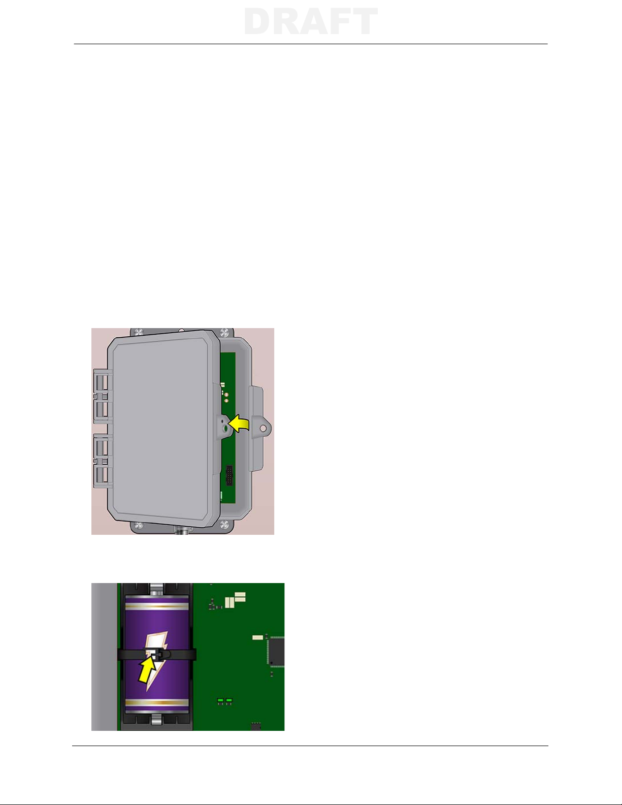
WARNING:
AVERTISSEMENT:
1) Remove any security hardware from the
EXPLOSION HAZARD - BATTERIES MUST ONLY BE CHANGED IN AN AREA KNOWN TO
BE NON-HAZARDOUS
RISQUE D'EXPLOSION
L’EMPLACEMENT EST DÉSIGNÉ NON DANGEREUX AVANT DE CHANGER LA BATTERIE.
- AFIN D’ÉVITER OUT RISQU D’EXPLOSION, S’ASURER QUE
MTU door.
2) Open the door of the MTU.
5) Remove the battery from the battery holder.
6) Insert the new battery into the battery
holder. The holder is keyed so the battery
can only be installed in one direction.
N
OTE: A backup capacitor will maintain MTU
memory during battery replacement
provided power is not removed for
longer than 10 minutes. Extended
power outages may require
recommissioning the MTU.
7) Secure the new battery into the holder by
threading the tapered end of the tie through
the open end and pulling until snug against
the battery.
8) Use the STAR Programmer to log the
battery replacement.
3) Note the polarity orientation of the battery.
4) Press in on the tab to release the battery tie.
Series 4000 Maintenance and Operations Manual 35
• Connect the STAR Programmer and select
Read MTU to record the battery
replacement in the activity log. Please see
Read MTU on page 17 for more
information.
• If the MTU was without power for an
extended period of time, use the Replace
MTU option on the STAR Programmer
Main Menu. Please see Replace MTU on
page 20 for more information.
9) Close and secure the MTU door according
to utility standard practices.
 Loading...