

A Fusion of the Art and Science of Light
CATHODE T100 PRODUCT DETAILS:
date: August 21, 2008
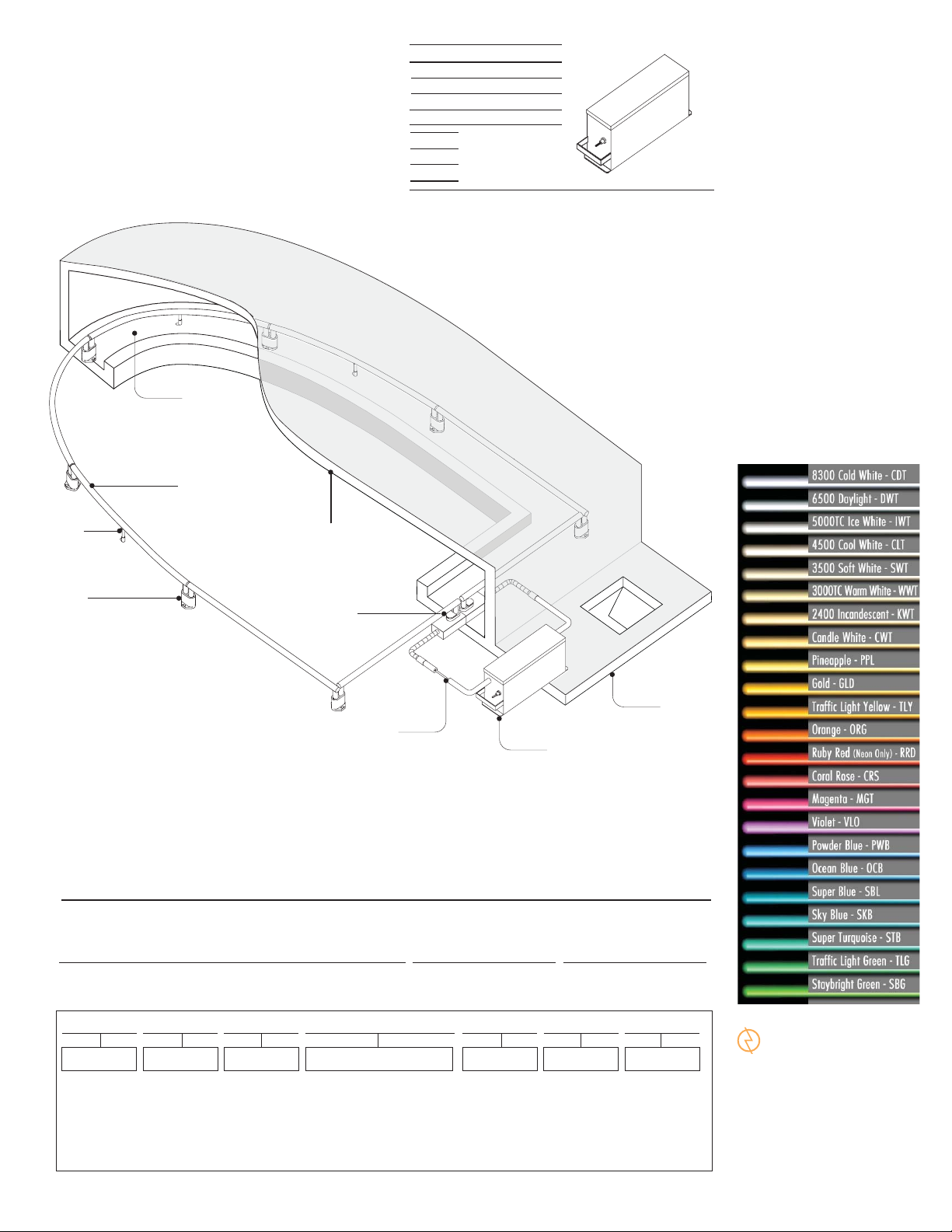
sheet description: Single Row Closed Loop
file: T100details.pdf
page:
1
F
B
T100 Specifications
Seven Lamp Transformer NPF 120mA
VA AMPS Sec.V
1080 9.4 9000
900 7.8 7500
600 5.2 5000
X
4.625”
Y
17.625”
Z
8.0”
(1) For 277V and HPF contact ACL.
(2) Use VA for computing loads. Use Watts for computing power consumption.
X
A. Transformer
B. Lamp
C. Intermediate
Lampholder
D. Feed Lampholder
E. GTO-15 in Conduit
F. Cove
G. Upper Ceiling
H. Lower Ceiling
I. Lamp Support
Z
Y
DETAILS
CATHODE T100
I
G
C
D
System Requirements
1. Secondary feeds must be equal in length and not exceed 20’
2. Only one single GTO-15 conductor for each conduit feed
3. Maximum length of lamp is 94”
4. Lamp lengths shall be standardized when ever possible
5. Transformer installed in accessable and vented area(s)
6. Sound rating approximately 33 decibels
7. Include detail(s) when possible
E
A
Note: Additional rows of lamps can be specified
either in whites or separate colors.
Single Row Closed Loop
© 2008 Architectural Cathode Lighting, Inc.
Project Name
SPECIFICATION CODE:
___ ___
(1)
T100
Product
Standard Output
7 Lamp Transformer
Cold Cathode System
(1) For our lower output system; T50, contact ACL. For a 1 lamp standard ballast system see B100. For a 2 lamp high output ballast system see B200.
(2) For multiple selections place a comma after each selection.
S01
Standard Color (s) Dim-able MountPrimaryEnvironment
S01
Note: For a variation (custom) of this product contact ACL to request a variation number and information.
DR - Dry
DP - Damp
See Chart
(2)
120V
277V -Special
Order
Linear FeetDate
DI - Dim
ND - Non Dim
H
S
S - Surface
NTS
ACL INC.
Architectural Cathode Lighting, Incorporated
cathodelighting.com
5301 Pacific Boulevard
Huntington Park California 90255 USA
Telephone 323.581.8800
Fax 323.581.7971
info@cathodelighting.com

A Fusion of the Art and Science of Light
CATHODE T100 PRODUCT DETAILS:
date: August 21, 2008
sheet description: Single Row End Feeds
file: T100details.pdf
page:
2
T100 Specifications
Seven Lamp Transformer NPF 120mA
VA AMPS Sec.V
1080 9.4 9000
900 7.8 7500
600 5.2 5000
X
4.625”
Y
17.625”
Z
8.0”
(1) For 277V and HPF contact ACL.
(2) Use VA for computing loads. Use Watts for computing power consumption.
G
X
A. Transformer
B. Lamp
C. Intermediate
Lampholder
D. Feed Lampholder
E. GTO-15 in Conduit
F. Cove
G. Upper Ceiling
H. Lower Ceiling
Z
Y
B
DETAILS
CATHODE T100
F
F
C
H
System Requirements
1. Secondary feeds must be equal in length and shall not exceed 20’
2. Only one single GTO-15 conductor for each conduit feed
3. Maximum length of lamp is 94”
4. Lamp lengths shall be standardized when ever possible
5. Transformer installed in accessable and vented area(s)
6. Sound rating approximately 33 decibels
7. Include details(s) when possible
A
E
Note: Additional rows of lamps can be specified
either in whites or separate colors.
Single Row End Feeds
© 2008 Architectural Cathode Lighting, Inc.
Project Name
SPECIFICATION CODE:
___ ___
(1)
T100
Product
Standard Output
7 Lamp Transformer
Cold Cathode System
(1) For our lower output system; T50, contact ACL. For a 1 lamp standard ballast system see B100. For a 2 lamp high output ballast system see B200.
(2) For multiple selections place a comma after each selection.
S01
Standard Color (s) Dim-able MountPrimaryEnvironment
S01
Note: For a variation (custom) of this product contact ACL to request a variation number and information.
DR - Dry
DP - Damp
See Chart
(2)
120V
277V -Special
Order
Linear FeetDate
DI - Dim
ND - Non Dim
S
S - Surface
D
NTS
ACL INC.
Architectural Cathode Lighting, Incorporated
cathodelighting.com
5301 Pacific Boulevard
Huntington Park California 90255 USA
Telephone 323.581.8800
Fax 323.581.7971
info@cathodelighting.com

A Fusion of the Art and Science of Light
CATHODE T100 PRODUCT DETAILS:
date: August 21, 2008
sheet description: Single Row Balanced Load
file: T100details.pdf
page:
3
T100 Specifications
Seven Lamp Transformer NPF 120mA
VA AMPS Sec.V
1080 9.4 9000
900 7.8 7500
600 5.2 5000
X
4.625”
Y
17.625”
Z
8.0”
(1) For 277V and HPF contact ACL.
(2) Use VA for computing loads. Use Watts for computing power consumption.
G
X
A. Transformer
B. Lamp
C. Intermediate
Lampholder
D. Feed Lampholder
E. Conduit
F. Cove
G. Upper Ceiling
H. Lower Ceiling
Z
Y
H
System Requirements
1. Secondary feeds must be equal in length and shall not exceed 20’
2. Only one single GTO-15 conductor for each conduit feed
3. Maximum length of lamp is 94”
4. Lamp lengths shall be standardized when ever possible
5. Transformer installed in accessable and vented area(s)
6. Sound rating approximately 33 decibels
7. Include details(s) when possible
A
Single Row
Balanced Load with Long Virtual Ground
DETAILS
B
F
C
E
Note: Additional rows of lamps can be specified
either in whites or separate colors.
D
NTS
CATHODE T100
© 2008 Architectural Cathode Lighting, Inc.
Project Name
SPECIFICATION CODE:
___ ___
(1)
T100
Product
Standard Output
7 Lamp Transformer
Cold Cathode System
(1) For our lower output system; T50, contact ACL. For a 1 lamp standard ballast system see B100. For a 2 lamp high output ballast system see B200.
(2) For multiple selections place a comma after each selection.
S01
Standard Color (s) Dim-able MountPrimaryEnvironment
S01
Note: For a variation (custom) of this product contact ACL to request a variation number and information.
DR - Dry
DP - Damp
See Chart
(2)
120V
277V -Special
Order
Linear FeetDate
DI - Dim
ND - Non Dim
S
S - Surface
ACL INC.
Architectural Cathode Lighting, Incorporated
cathodelighting.com
5301 Pacific Boulevard
Huntington Park California 90255 USA
Telephone 323.581.8800
Fax 323.581.7971
info@cathodelighting.com

A Fusion of the Art and Science of Light
CATHODE T100 PRODUCT DETAILS:
date: August 21, 2008
sheet description: Double Row Balanced Load
file: T100details.pdf
page:
4
T100 Specifications
Seven Lamp Transformer NPF 120mA
VA AMPS Sec.V
1080 9.4 9000
900 7.8 7500
600 5.2 5000
X
4.625”
Y
17.625”
Z
8.0”
(1) For 277V and HPF contact ACL.
(2) Use VA for computing loads. Use Watts for computing power consumption.
G
X
A. Transformer
B. Lamp
C. Intermediate
Lampholder
D. Feed Lampholder
E. Conduit
F. Cove
G. Upper Ceiling
Z
Y
Virtual Ground
with Connecting
Feed Lampholder
System Requirements
1. Secondary feeds must be equal in length and not exceed 20’
2. Only one single GTO-15 conductor for each conduit feed
3. Maximum length of lamp is 94”
4. Lamp lengths shall be standardized when ever possible
5. Transformer installed in accessable and vented area(s)
6. Sound rating approximately 33 decibels
7. Include detail(s) when possible
Double Row
Balanced Load with Short Virtual Ground
© 2008 Architectural Cathode Lighting, Inc.
B
DETAILS
CATHODE T100
F
C
D
A
E
Note: Additional rows of lamps can be specified
either in whites or separate colors.
NTS
Project Name
SPECIFICATION CODE:
___ ___
(1)
T100
Product
Standard Output
7 Lamp Transformer
Cold Cathode System
(1) For our lower output system; T50, contact ACL. For a 1 lamp standard ballast system see B100. For a 2 lamp high output ballast system see B200.
(2) For multiple selections place a comma after each selection.
S01
Standard Color (s) Dim-able MountPrimaryEnvironment
S01
Note: For a variation (custom) of this product contact ACL to request a variation number and information.
DR - Dry
DP - Damp
See Chart
(2)
120V
277V -Special
Order
Linear FeetDate
DI - Dim
ND - Non Dim
S
S - Surface
ACL INC.
Architectural Cathode Lighting, Incorporated
cathodelighting.com
5301 Pacific Boulevard
Huntington Park California 90255 USA
Telephone 323.581.8800
Fax 323.581.7971
info@cathodelighting.com

A Fusion of the Art and Science of Light
CATHODE T100 PRODUCT DETAILS:
date: August 21, 2008
sheet description: Single Row Opposite Coves
file: T100details.pdf
page:
5
T100 Specifications
Seven Lamp Transformer NPF 120mA
VA AMPS Sec.V
1080 9.4 9000
900 7.8 7500
600 5.2 5000
X
4.625”
Y
17.625”
Z
8.0”
(1) For 277V and HPF contact ACL.
(2) Use VA for computing loads. Use Watts for computing power consumption.
X
Z
Y
A
Secondary Feed
System Requirements
1. Secondary feeds must be equal in length and not exceed 20’
2. Only one single GTO-15 conductor for each conduit feed
3. Maximum length of lamp is 94”
4. Lamp lengths shall be standardized when ever possible
5. Transformer installed in accessable and vented area(s)
6. Sound rating approximately 33 decibels
7. Include detail(s) when possible
A. Transformer
B. Lamp
C. Intermediate
Lampholder
D. Feed Lampholder
E. Conduit
F. Cove
G. Upper Ceiling
B
G
F
C
H
H. Lower Ceiling
D
E
DETAILS
CATHODE T100
Virtual Ground
Note: Additional rows of lamps can be specified
either in whites or separate colors.
Single Row in Opposite Coves
© 2008 Architectural Cathode Lighting, Inc.
Balanced Load with Virtual Ground
Project Name
SPECIFICATION CODE:
___ ___
(1)
T100
Product
Standard Output
7 Lamp Transformer
Cold Cathode System
(1) For our lower output system; T50, contact ACL. For a 1 lamp standard ballast system see B100. For a 2 lamp high output ballast system see B200.
(2) For multiple selections place a comma after each selection.
S01
Standard Color (s) Dim-able MountPrimaryEnvironment
S01
Note: For a variation (custom) of this product contact ACL to request a variation number and information.
DR - Dry
DP - Damp
See Chart
(2)
120V
277V -Special
Order
Linear FeetDate
DI - Dim
ND - Non Dim
S
S - Surface
NTS
ACL INC.
Architectural Cathode Lighting, Incorporated
cathodelighting.com
5301 Pacific Boulevard
Huntington Park California 90255 USA
Telephone 323.581.8800
Fax 323.581.7971
info@cathodelighting.com

A Fusion of the Art and Science of Light
CATHODE T100 PRODUCT DETAILS:
date modified: August 21, 2008
sheet description: Surface Details
note: Recommended Minimum Dimensions
file: T100details.pdf
page:
6
4" Min.
5" Min. Recommended
from 6" to 12"
2 1/4"
2 1/2"
25mm Cold
Cathode Lamp
T100 Surface
Lampholder
EQ
EQ
3"
T100 Specifications
Seven Lamp Transformer NPF 120mA
VA AMPS Sec.V
1080 9.4 9000
900 7.8 7500
600 5.2 5000
X
4.625”
Y
17.625”
Z
8.0”
(1) For 277V and HPF contact ACL.
(2) Use VA for computing loads. Use Watts for computing power consumption.
T100 Surface
Lampholder
25mm Cold
Cathode Lamp
5"
EQ
X
3"
2 1/2"
2 1/4"
EQ
4" Min.
Z
Y
5" Min.
DETAILS
CATHODE T100
Cove Section
A
Base Mounted Lampholder
8 1/2"2 1/2"
T100 Surface
Lampholder
25MM Cold
Cathode Lamp
3"
1 5/8"
4 3/4"
Cove Section
C
Wall Mounted Lampholder
© 2008 Architectural Cathode Lighting, Inc.
Project Name
SPECIFICATION CODE:
___ ___
(1)
T100
Product
Standard Output
7 Lamp Transformer
Cold Cathode System
(1) For our lower output system; T50, contact ACL. For a 1 lamp standard ballast system see B100. For a 2 lamp high output ballast system see B200.
(2) For multiple selections place a comma after each selection.
S01
Standard Color (s) Dim-able MountPrimaryEnvironment
S01
Note: For a variation (custom) of this product contact ACL to request a variation number and information.
DR - Dry
DP - Damp
3"
See Chart
(2)
Pocket Section
B
Ceiling Mounted Lampholder
5" Minimum
120V
277V -Special
Order
Linear FeetDate
DI - Dim
ND - Non Dim
S
S - Surface
ACL INC.
Architectural Cathode Lighting, Incorporated
cathodelighting.com
5301 Pacific Boulevard
Huntington Park California 90255 USA
Telephone 323.581.8800
Fax 323.581.7971
info@cathodelighting.com
 Loading...