

AC International 8200 User Manual
Instruction Manual
AC2675
REVISION A
8200 Series Base Mounted
Centrifugal Fire Pumps
Installation, Operation and Service Instructions
INSTALLER: PLEASE LEAVE THIS MANUAL FOR THE OWNER’S USE.
1

TABLE OF CONTENTS
DESCRIPTION......................................................3
OPERATIONAL LIMITS .......................................3
MAXIMUM WORKING PRESSURE.....................3
SEAL OPERATING LIMITS .................................3
PACKING ......................................................3
PUMP IDENTIFICATION......................................3
SAFETY INSTRUCTIONS....................................4
ADDITIONAL SAFETY REQUIREMENTS:...4
ADDITIONAL SAFETY REQUIREMENTS:..........5
ELECTRICAL SAFETY: ................................5
THERMAL SAFETY: .....................................5
MECHANICAL SAFETY:...............................5
INSTALLATION....................................................6
PUMP LOCATION.........................................6
RECEIVING PUMP .......................................6
TEMPORARY STORAGE .............................7
LOCATION ....................................................7
FOUNDATION...............................................7
BASE PLATE SETTING (BEFORE PIPING) 8
GROUTING PROCEDURE ...........................8
SEE ANSI/OSHA COUPLER GUARD
REMOVAL/INSTALLATION ..................8
ALIGNMENT PROCEDURE .........................8
ANSI/OSHA COUPLER GUARD
REMOVAL/INSTALLATION ..................9
DOWELING .................................................11
SUCTION AND DISCHARGE PIPING........11
STUFFING BOX LUBRICATION.................14
PACKING ....................................................14
MAINTENANCE TIME TABLE...........................19
TROUBLE SHOOTING ......................................20
CHANGING ROTATION .................................... 23
SERVICE INSTRUCTIONS................................24
DISASSEMBLY AND REASSEMBLY
PROCEDURES................................... 24
DISMANTLING (PUMP WITH PACKING) .. 24
ASSEMBLY (PUMP WITH PACKING) ....... 27
APPENDIX “A” ENGINEERING DATA.............30
APPENDIX “B” ..................................................31
EXPLODED VIEW – 8200 SERIES FIRE
PUMP .................................................. 31
REPLACEMENT PARTS LIST ...................32
INSTRUCTIONS FOR ORDERING PARTS33
APPENDIX “C” FIELD TEST REPORT ............ 34
USEFUL FORMULAS................................. 35
NOTE
The information contained in this book is intended
to assist operating personnel by providing
information on the characteristics of the purchased
equipment.
It does not relieve the user of their responsibility of
using accepted engineering practices in the
installation, operation, and maintenance of this
equipment.
Any further questions, contact ITT A-C Pump,
(847) 966-3700.
OPERATION.......................................................16
PRE-START CHECKS ................................16
PRIMING .....................................................16
STARTING ..................................................16
OPERATING CHECKS ...............................16
FREEZING PROTECTION..........................17
FIELD TESTING..........................................17
MAINTENANCE..................................................17
GENERAL MAINTENANCE ........................17
MAINTENANCE OF PUMP DUE TO FLOOD
DAMAGE .............................................17
BEARING LUBRICATION – GREASE........18
PACKING SEAL ..........................................18
CLEANING WITHOUT DISMANTLING
PUMP ..................................................18
2
DESCRIPTION
The 8200 Series Centrifugal Fire Pumps are
framed mounted pumps which feature – high
efficiency, rugged construction, compact
design, foot mounted volute and regreasable
bearings. These features, along with the
horizontal split case, make installation,
operation and service easy to perform.
OPERATIONAL LIMITS
Unless special provisions have been made
for your pump by ITT A-C Fire Pump
Systems, the operational limits for 8200
Series Centrifugal Fire Pumps are as follows:
MAXIMUM WORKING PRESSURE
Listed on pump nameplate.
SEAL OPERATING LIMITS
PACKING
PH Limitations 7-9; Temperature Range 0 to
+200°F
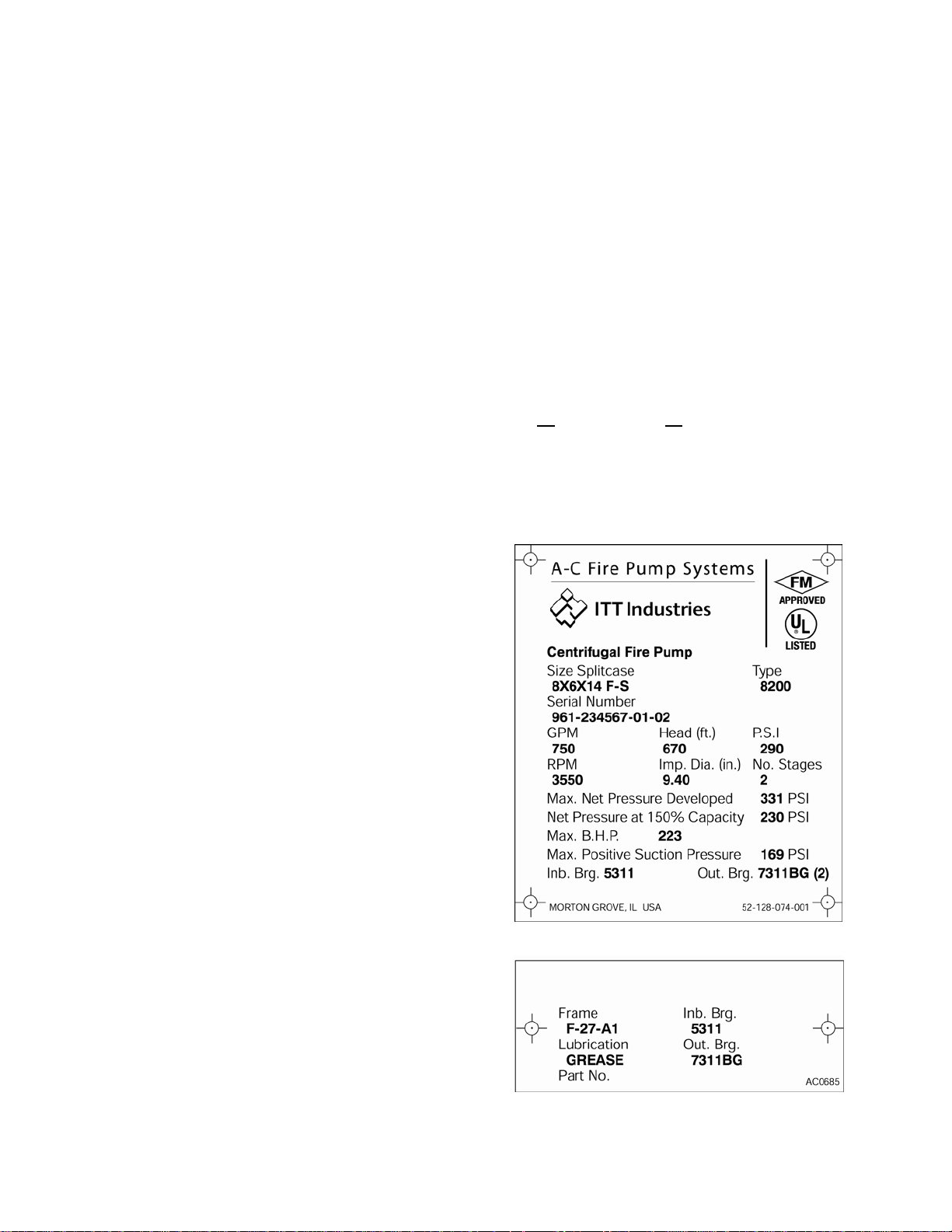
PUMP IDENTIFICATION
There are two identification plates on each
pump. The pump rating plate gives
identification and rating information. Figure 1
shows an example of a typical Rating Plate.
Permanent records for this pump are
referenced by the Serial Number and it must,
therefore, be used with all correspondence to
order all spare parts and replacement parts.
The fourth digit indicates the specific pump
on orders for more than one pump. For
example, if an order called for six pumps, all
pumps would have the same first three sets
of digits and the last digit will change to
identify each of the six. (e.g. 03-123456-0101
, 03-123456-01-02, etc.)
The frame plate, shown below in Figure 2,
gives information concerning the bearings
and their lubrication. The inboard and
outboard bearing numbers refer to the
bearing manufacturer’s numbers.
For use on open or closed systems which
require a large amount of makeup water, as
well as systems which are subjected to widely
varying chemical conditions and solids
buildup.
FIGURE 1 – RATING PLATE
FIGURE 2 – FRAME PLATE
3
SAFETY INSTRUCTIONS
SAFETY INSTRUCTIONS
This safety alert symbol will be used in this
manual and on the pump safety instruction decals
to draw attention to safety related instructions.
When used the safety alert symbol means
ATTENTION! BECOME ALERT! YOUR SAFETY
IS INVOLVED! FAILURE TO FOLLOW THE
INSTRUCTIONS MAY RESULT IN A SAFETY
HAZARD.
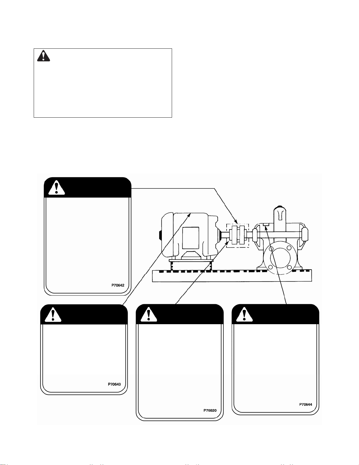
Your 8200 Series Centrifugal Fire Pump should
have the following safety instruction decals
displayed. If the decals are missing or illegible
contact your local ITT A-C Fire Pump Systems
representative for a replacement.
ADDITIONAL SAFETY REQUIREMENTS:
1. Electrical connections to be made by
qualified Electrician in accordance with all
national, state and local codes.
2. Motor must have properly sized starter
with properly sized heaters to provide
overload and undervoltage protection.
3. If pump, motor or piping are operating at
extremely high or low temperatures,
guarding or insulation is required.
4. The maximum working pressure of the
pump is listed on the pump nameplate, do
not exceed this pressure.
WARNING
ROTATING COMPONENTS
DISCONNECT AND LOCKOUT
POWER BEFORE SERVICING.
DO NOT OPERATE WITHOUT
ALL GUARDS IN PLACE.
CONSULT INSTALLATION
AND SERVICE INSTRUCTION
SHEET BEFORE OPERATING
OR SERVICING.
FAILURE TO FOLLOW
INSTRUCTIONS COULD
RESULT IN INJURY
OR DEATH.
WARNING
EYEBOLTS OR LIFTING
LUGS IF PROVIDED ARE
FOR LIFTING ONLY THE
COMPONENTS TO WHICH
THEY ARE ATTACHED.
FAILURE TO FOLLOW
INSTRUCTIONS COULD
RESULT IN INJURY
OR DEATH.
COUPLER ALIGNMENT IS
REQUIRED! LEVEL AND
GROUT PUMP BEFORE USE!
CHECK ALIGNMENT BEFORE
GROUTING, AFTER SYSTEM
IS FILLED, AFTER SERVICING
PUMP, AND AS REQUIRED.
CONSULT THE SERVICE
INSTRUCTIONS FOR DETAILS.
FAILURE TO FOLLOW THESE
INSTRUCTIONS COULD
RESULT IN INJURY OR
PROPERTY DAMAGE.
CAUTIONCAUTION
DO NOT RUN PUMP DRY,
SEAL DAMAGE MAY OCCUR.
INSPECT PUMP SEAL
REGULARKY FOR LEAKS,
REPLACE AS REQUIRED.
FOR LUBRICATION
REQUIREMENTS, CONSULT
SERVICE INSTRUCTIONS.
FAILURE TO FOLLOW
INSTRUCTIONS COULD
RESULT IN INJURY OR
PROPERTY DAMAGE.
FIGURE 3 - SAFETY INSTRUCTION DECALS
4
ADDITIONAL SAFETY REQUIREMENTS:
ELECTRICAL SAFETY:
WARNING: Electrical Shock Hazard
Electrical connections to be made by a
qualified electrician in accordance with all
applicable codes, ordinances, and good practices.
Failure to follow these instructions could result in
serious personal injury or death, and property
damage.
WARNING: Electrical Overload Hazard
Three phase motors must have properly
sized heaters to provide overload and under
voltage protection. Single-phase motors have
built-in overload protectors. Failure to follow these
instructions could result in serious personal injury
or death, and property damage.
THERMAL SAFETY:
WARNING: Extreme Temperature
Hazard
If pump, motor, or piping is operating at extremely
high or low temperature, guarding or insulation is
required. Failure to follow these instructions could
result in serious personal injury or death, and
property damage.
MECHANICAL SAFETY:
WARNING: Unexpected Startup Hazard
Disconnect and lockout power before
servicing. Failure to follow these instructions could
result in serious personal injury or death, and
property damage.
WARNING: Excessive System Pressure
Hazard
The maximum working pressure of the pump is
listed on the nameplate, do not exceed this
pressure. Failure to follow these instructions could
result in serious personal injury or death, and
property damage.
WARNING: Excessive Pressure Hazard
Volumetric Expansion
WARNING
The heating of water and other fluids causes
volumetric expansion. The associated forces may
cause failure of system components and release
of high temperature fluids. Installing properly sized
and located compression tanks and pressure relief
valves will prevent this. Failure to follow these
instructions could result in serious personal injury
or death, and property damage.
CAUTION
WARNING
5

INSTALLATION
PUMP LOCATION
Locate the pump so there is sufficient room
for inspection, maintenance and service. If
the use of a hoist or tackle is needed, allow
ample head room.
WARNING: Falling Objects Hazard
Eyebolts or lifting lugs, if provided, are for
lifting only the components to which they are
attached. Failure to follow these instructions could
result in serious personal injury or death, or
property damage.
If lifting base pump is required, use a nylon
string, chain, or wire rope, hitch around both
bearing supports. If lifting of the entire pump is
required, do so with slings placed under the
base rails as shown.
Care must be taken to size equipment for
unbalanced loads which may exist if the
motor is not mounted on the base at the time
of lifting. Motor may or may not be mounted
at the factory.
Pump, base, and driver assemblies where the
base length exceeds 100 inches may not be
safe to lift as a complete assembly. Damage to
the baseplate may occur. If the driver has
been mounted on the baseplate at the factory,
it is safe to lift the entire assembly. If the driver
has not been mounted at the factory, and the
overall baseplate length exceeds 100 inches,
do not lift the entire assembly consisting of
pump, base, and driver. Instead, lift the pump
and baseplate to its final location without the
driver. Then mount the driver.
The best pump location for sound and
vibration ab-sorption is on a concrete floor
with subsoil underneath. If the pump location
is overhead, special precautions should be
undertaken to reduce possible sound
transmission. Consult a sound specialist.
CHOKER
HITCH
AROUND
BEARING
FRAME
FIGURE 4
If the pump is not on a closed system, it
should be placed as near as possible to the
source of the liquid supply, and located to
permit installation with the fewest number of
bends or elbows in the suction pipe.
The installation must be evaluated to
determine that the Net Positive Suction Head
Available (NPSHA) meets or exceeds the Net
Positive Suction Head Required (NPSHR), as
stated by the pump performance curve. See
page 11 for more details on proper suction
piping installation.
RECEIVING PUMP
Check pump for shortages and damage
immediately upon arrival. (An absolute must.)
Prompt reporting to the carrier’s agent with
notations made on the freight bill, will
expedite satisfactory adjustment by the
carrier.
Pumps and drivers normally are shipped from
the factory mounted and painted with primer
and one finish coat. Couplings may be either
completely assembled or have the coupling
hubs mounted on the shafts and the
connecting members removed. When the
connecting members are removed, they will
be packaged in a separate container and
shipped with the pump or attached to the
base plate.
NYLON SLING,
CHAIN OR WIRE
ROPE
Shafts are in alignment when the unit is
shipped; however, due to shipping, the
pumps may arrive mis-aligned and, therefore,
alignment must be established during
6
installation. ITT AC Fire Pump Systems has
determined that proper and correct alignment
can only be made by accepted erection
practices. Refer to the following paragraphs
on “Foundation,” “Base Plate Setting,”
“Grouting Procedure,” “Alignment Procedure”
and “Doweling.”
collect should be blown out with compressed
air.
Make sure there is a suitable power source
available for the pump driver. If motor driven,
electrical characteristics should be identical to
those shown on motor data plate.
TEMPORARY STORAGE
If the pump is not to be installed and operated
soon after arrival, store it in a clean, dry place
having slow, moderate changes in ambient
temperature. Rotate the shaft periodically to
coat the bearings with lubricant and to retard
oxidation, corrosion, and to reduce the
possibility of false brinelling of the bearings.
LOCATION
The pump should be installed as near the
suction supply as possible, but no less than
five suction diameters (refer to page 11,
suction and discharge piping section) with the
shortest and most direct suction pipe
practical. The total dynamic suction lift (static
lift plus friction losses in suction line) should
not exceed the limits for which the pump was
sold.
The pump must be primed before starting.
Whenever possible, the pump should be
located below the fluid level to facilitate
priming and assure a steady flow of liquid.
This condition provides a positive suction
head on the pump. It is also possible to prime
the pump by pressurizing the suction vessel.
When installing the pump, consider its
location in relation to the system to assure
that sufficient Net Positive Suction Head
(NPSH) at pump suction is provided.
Available NPSH must always equal or exceed
the required NPSH of the pump.
FOUNDATION
A substantial foundation and footing should
be built to suit local conditions. The
foundation must be substantial enough to
absorb vibration. (Hydraulic Institute
Standards recommends the foundation weigh
at least five (5) times the weight of the pump
unit.) It must form a permanent and rigid
support for the baseplate. This is important in
maintaining the alignment of the flexibly
coupled unit.
The foundation should be poured without
interruption to within 1/2 to 1-1/2 inches of the
finished height. The top surface of the
foundation should be well scored and
grooved before the concrete sets; this
provides a bonding surface for the grout.
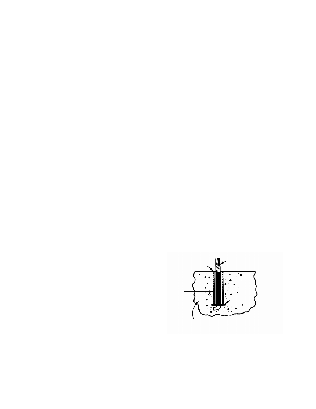
Foundation bolts should be set in concrete as
shown in Figure 5. An optional 4-inch long
tube around the bolts at the top of the
concrete will allow some flexibility in bolt
alignment to match the holes in the base
plate. Allow enough bolt length for grout,
shims, lower base plate flange, nuts and
washers. The foundation should be allowed
to cure for several days before the base plate
is shimmed and grouted.
FOUNDATION
PIPE SLEEVE
BOLT
The pump should be installed with sufficient
accessibility for inspection and maintenance.
A clear space with ample head room should
be allowed for the use of an overhead crane
or hoist sufficiently strong to lift the unit.
NOTE: Allow sufficient space to be able to
dismantle pump without disturbing the pump
inlet and discharge piping.
Select a dry place above the floor level
wherever possible. Take care to prevent
pump from freezing during cold weather when
not in operation. Should the possibility of
freezing exist during a shut-down period, the
pump should be completely drained, and all
passages and pockets where liquid might
7
(OPTIONAL)
WASHER
BUILT-UP CONCRETE
FOUNDATION
FIGURE 5 – FOUNDATION
BASE PLATE SETTING (BEFORE PIPING)
NOTE: This procedure assumes that a
concrete foundation has been prepared with
anchor or hold down bolts extending up ready
to receive unit. It must be understood that
pump and motor have been mounted and
rough aligned at the factory. If motor is to be
field mounted, consult factory for
recommendations. ITT AC Fire Pump
Systems cannot assume responsibility for
final alignment.
operator). Final alignment procedures are
covered under “Alignment Procedures.”
e. Check to make sure the piping can be
aligned to the pump flanges without
placing pipe strain on either flange.
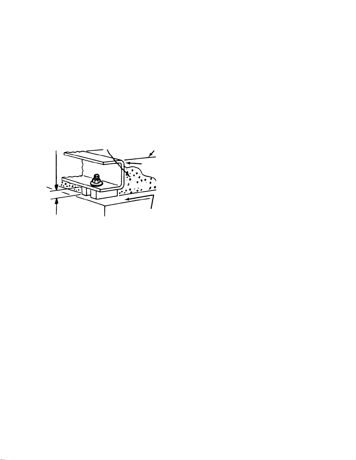
f. Grout in base plate completely (See
“Grouting Procedure”) and allow grout to
dry thoroughly before attaching piping to
pump. (24 hours is sufficient time with
approved grouting procedure.)
ALLOW 1" FOR
SHIMS. PLACE ON
BOTH SIDES OF
ANCHOR BOLTS.
APPROX. 1" GAP
LEVELING OF PUMP BASE
ON CONCRETE FOUNDATION.
NOTE:
TO KEEP SHIMS IN
PLACE ALLOW GROUT
TO FLOW AROUND
HOLD DOWN LUGS.
FIGURE 6 – SETTING BASE PLATE AND
GROUTING
a. Use blocks and shims under base for
support at anchor bolts and midway
between bolts, to position base
approximately 1" above the concrete
foundation, with studs extending through
holes in the base plate.
b. By adding or removing shims under the
base, level and plumb the pump shaft and
flanges. The base plate does not have to
be level.
c. Draw anchor nuts tight against base, and
observe pump and motor shafts or
coupling hubs for alignment. (Temporarily
remove coupling guard for checking
alignment.)
d. If alignment needs improvement, add
shims or wedges at appropriate positions
under base, so that retightening of anchor
nuts will shift shafts into closer alignment.
Repeat this procedure until a reasonable
alignment is reached.
NOTE: Reasonable alignment is defined as
that which is mutually agreed upon by pump
contractor and the accepting facility (final
GROUT ONLY TO
TOP OF BASE RAIL.
PUMP BASE
RAIL
GROUT
CONCRETE
FOUNDATION
GROUTING PROCEDURE
Grout compensates for uneven foundation,
distributes weight of unit, and prevents
shifting. Use an approved, non-shrinking
grout, after setting and leveling unit (See
Figure 6).
a. Build strong form around the foundation to
contain grout.
b. Soak top of concrete foundation
thoroughly, then remove surface water.
c. Base plate should be completely filled with
grout.
d. After the grout has thoroughly hardened,
check the foundation bolts and tighten if
necessary.
e. Check the alignment after the foundation
bolts are tightened.
f. Approximately 14 days after the grout has
been poured or when the grout has
thoroughly dried, apply an oil base paint to
the exposed edges of the grout to prevent
air and moisture from coming in contact
with the grout.
SEE ANSI/OSHA COUPLER GUARD
REMOVAL/INSTALLATION
(SEE BELOW)
ALIGNMENT PROCEDURE
NOTE: A flexible coupling will only
compensate for small amounts of
misalignment. Permissible misalignment will
vary with the make of coupling. Consult
coupling manufacturer’s data when in doubt.
Allowances are to be made for thermal
expansion during cold alignment, so that the
coupling will be aligned at operating
temperature. In all cases, a coupling must be
in alignment for continuous operation. Even
though the coupling may be lubricated,
misalignment causes excessive wear,
8
vibration, and bearing loads that result in
premature bearing failure and ultimate seizing
of the pump. Misalignment can be angular,
parallel, or a combination of these, and in the
horizontal and vertical planes. Final alignment
should be made by moving and shimming the
motor on the base plate, until the coupling
hubs are within the recommended tolerances
measured in total run-out. All measurements
should be taken with the pump and motor foot
bolts tightened. The shaft of sleeve bearing
motors should be in the center of its
mechanical float.
NOTE: Proper alignment is essential for
correct pump operation. This should be
performed after base plate has been properly
set and grout has dried thoroughly according
to instructions. Final alignment should be
made by shimming driver only. Alignment
should be made at operating temperatures.
WARNING: Unexpected Start-up Hazard
Disconnect and lock out power before
servicing. Failure to follow these instructions could
result in serious personal injury or death and
property damage.
ANSI/OSHA COUPLER GUARD
REMOVAL/INSTALLATION
WARNING: Unexpected Start-up Hazard
Disconnect and lock out power before
servicing. Failure to follow these instructions could
result in serious personal injury or death and
property damage.
NOTE: Do not spread the inner and outer
guards more than necessary for guard
removal or installation. Over spreading the
guards may alter their fit and appearance.
Removal
a. Remove the two capscrews that hold the
outer (motor side) coupler guard to the
support bracket(s).
b. Spread the outer guard and pull it off the
inner guard.
c. Remove the capscrew that holds the inner
guard to the support bracket.
d. Spread the inner guard and pull it over the
coupler.
Installation
a. Check coupler alignment before
proceeding. Correct if necessary.
b. Spread the inner guard and place it over
the coupler.
c. With the inner guard straddling the
support bracket, install a capscrew
through the hole (or slot) in the support
bracket and guard located closest to the
pump. Do not tighten the capscrew.
d. Spread the outer guard and place it over
the inner guard.
e. Install the outer guard capscrews by
following the step stated below which
pertains to your particular pump:
i. For pumps with a motor saddle support
bracket: Ensure the outer guard is
straddling the support arm, and install
but do not tighten the two remaining
capscrews.
ii. For pumps without a motor saddle
support bracket: Insert the spacer
washer between the holes located
closest to the motor in the outer guard,
and install, but do not tighten, the two
remaining capscrews.
f. Position the outer guard so it is centered
around the shaft, and so there is less than
a 1/4" of the motor shaft exposed. On
guards that utilize a slotted support
bracket, the inner guard will have to be
positioned so there is only a 1/4" of the
pump shaft exposed.
g. Holding the guard in this position, tighten
the three capscrews.
9
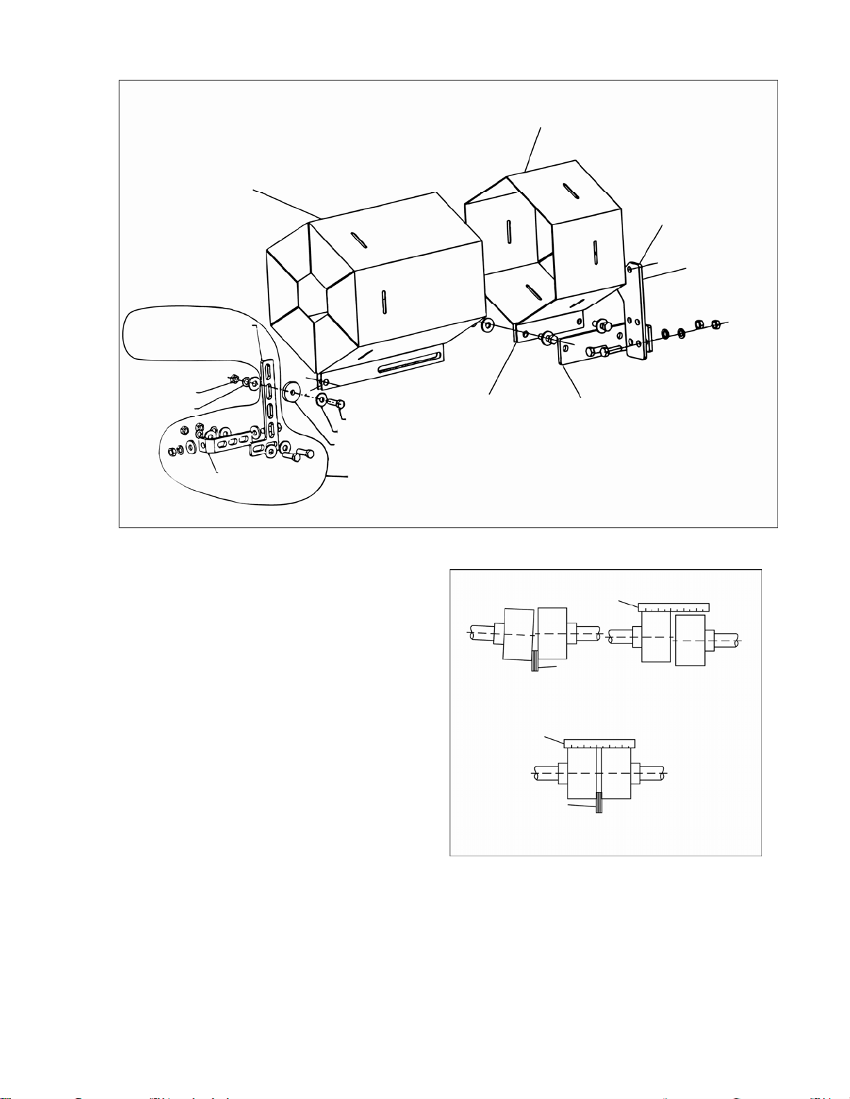
ANSI/OSHA Coupling Guard Exploded View
For Typical 8200 Series Fire Pump Installation
OUTER GUARD
LOCATE SUPPORT ARM
BETWEEN OUTER GUARD ENDS.
ALIGN THE ARM WITH HOLES IN
THE OUTER GUARD AND HOLES
IN THE SADDLE BRACKET.
INNER GUARD
ATTACH SUPPORT BRACKET
TO BEARING HOUSING
SUPPORT
BRACKET
NUT
LOCKWASHER
MOTOR SADDLE
BRACKET ATTACH
TO MOTOR SADDLE
CAPSCREW
FLAT WASHER
SPACER WASHER
THIS OPTION USED IN PLACE OF SPACER WHERE
OVERALL LENGTH OF GUARD EXCEEDS 12 INCHES
OR GUARD WITH IS OVER 10 INCHES ACROSS
THE FLATS.
Method 1 – Straight Edge Alignment for
Standard Sleeve Type Coupler with Black
Rubber Insert
(See Figure 7A)
Proceed with this method only if satisfied that
face and outside diameters of the coupling
halves are square and concentric with the
coupling borers. If this condition does not
exist or elastomeric couplings do not make
this method convenient, use Method 2.
1. Check angular misalignment using a
micrometer or caliper. Measure from the
outside of one flange to the outside of the
opposite flange at four points 90° apart.
DO NOT ROTATE COUPLER.
Misalignment up to 1/64" per inch of
coupler radius is permissible.
2. At four points 90° apart (DO NOT
ROTATE COUPLER), measure the
parallel coupler misalignment by laying a
straight edge across one coupler half and
measuring the gap between the straight
edge and opposite coupler half. Up to a
1/64" gap is permissible.
BRACKET SUPPORT
ATTACHED INSIDE HERE
IN LINE WITH BOLT
ANGULAR ALIGNMENT PARALLEL ALIGNMENT
BRACKET
SUPPORT
STRAIGHT EDGE
FEELER GAGE
INCORRECT ALIGNMENT
STRAIGHT EDGE
FEELER GAGE
CORRECT ALIGNMENT
FIGURE 7A – CHECKING ALIGNMENT
(METHOD 1)
10
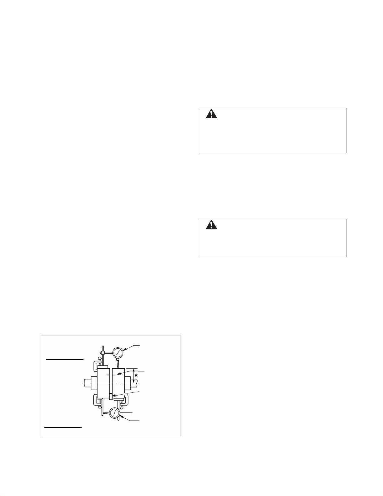
Method 2 – For Orange Hytrel Insert, 3500
RPM Operation, or All Other Coupler
Types
(See Figure 7B)
a. Make sure each hub is secured to its
respective shaft and that all connecting
and/or spacing elements are removed at
this time.
b. The gap between the coupling hubs is set
by the manufacturer before the units are
shipped. However, this dimension should
be checked. (Refer to the coupling
manufacturer’s specifications supplied
with the unit.)
c. Scribe index lines on coupling halves as
shown in Figure 7B.
d. Mount dial indicator on one hub as shown
for parallel alignment. Set dial to zero.
e. Turn both coupling halves so that index
lines remain matched. Observe dial
reading to see whether driver needs
adjustment (See paragraph i below).
f. Mount dial indicator on one hub as shown
for angular alignment. Set dial to zero.
g. Turn both coupling halves so that index
lines remain matched. Observe dial
reading to see whether driver needs
adjustment (See paragraph i below).
h. Assemble coupling. Tighten all bolts and
set screw(s). It may be necessary to
repeat steps c through f for a final check.
i. For single element couplings, a
satisfactory parallel misalignment is
.004"T.I.R., while a satisfactory angular
misalignment is .004"T.I.R. per inch of
radius R (See Figure 7B).
DIAL
PARALLEL
INDICATOR
ALIGNMENT
INDEX LINE
Final Alignment
Final alignment cannot be accomplished until
the pump has been operated initially for a
sufficient length of time to attain operating
temperature. When normal operating
temperature has been attained, secure the
pump to re-check alignment and compensate
for temperature accordingly. See Alignment
Section.
WARNING: Rotating Components
Hazard
Do not operate pump without all guards in place.
Failure to follow these instructions could result in
serious personal injury or death and property
damage.
OPTIONAL Alignment Procedure
If desired, the pump and motor feet can be
doweled to the base after final alignment is
complete. This should not be done until the
unit has been run for a sufficient length of
time and alignment is within the tolerance.
See Doweling Section.
CAUTION: Extreme Temperature and/or
Flying Debris Hazard
Eye protection and gloves required. Failure to
follow these instructions could result in property
damage and/or moderate personal injury.
NOTE: Pump may have been doweled to
base at factory.
DOWELING
Dowel the pump and driving unit as follows:
a. Drill holes through diagonally opposite feet
and into the base. Holes must be of a
diameter 1/64 inch less than the diameter
of the dowel pins. Clean out the chips.
b. Ream the holes in feet and base to the
proper diameter for the pins (light push fit).
Clean out the chips.
c. Insert pins to be approximately flush with
feet.
RESILIENT
SEPARATOR
ANGULAR
ALIGNMENT
DIAL
INDICATOR
FIGURE 7B – CHECKING ALIGNMENT
(METHOD 2)
SUCTION AND DISCHARGE PIPING
General
When installing the pump piping, be sure to
observe the following precautions:
Piping should always be run to the pump.
Do not move pump to pipe. This could make
final alignment impossible.
Both the suction and discharge piping should
be supported independently near the pump
11
 Loading...