


USER MANUALUSER MANUAL
AXIAL SERIES
PROJECT COOLING FANS


3
WELCOME
Thank you for choosing AC Infinity. We are committed to product quality and friendly customer service.
If you have any questions or suggestions, please don’t hesitate to contact us. Visit www.acinfinity.com
and click contact for our contact information.
EMAIL
support@acinfinity.com
WEB
www.acinfinity.com
LOCATION
Los Angeles, CA

4
MANUAL CODE AF1802X1
PRODUCT
AXIAL 8025
AXIAL 8038
AXIAL 9225
AXIAL 9238
AXIAL 1225
AXIAL 1238
AXIAL 1751
AXIAL S1225
AXIAL S1225D
AXIAL S1238
AXIAL S1238D
AXIAL LS1238
MODEL
HS8025A-X
LS8038A-X
HS9225A-X
HS9238A-X
LS1225A-X
HS1238A-X
HS1751A-X
AI-120SCX
AI-120SCXD
AI-1238SCX
AI-1238SCXD
LS1238A-X
UPC-A
854759004259
854759004273
854759004228
854759004266
854759004211
854759004181
854759004303
854759004129
854759004150
819137020078
819137020085
819137020542

5
MANUAL INDEX
Manual Index .................................................................................
Fan Specifications .........................................................................
Key Features .................................................................................
Product Contents ...........................................................................
Fan Replacement ..........................................................................
Mounting ........................................................................................
Powering ........................................................................................
Speed Controller ............................................................................
Other AC Infinity Products .............................................................
Warranty ........................................................................................
Page 5
Page 6
Page 7
Page 8
Page 9
Page 12
Page 15
Page 16
Page 17
Page 18

6
FAN SPECIFICATIONS
CASE SIZE
Square axial fans come in the standard sizes set by the industry. They are commonly quoted with
millimeters in the format length time height times width. A case size measuring 120 mm tall, 120
mm long, and 38 mm wide may be quoted as 120 x 120 x 38 mm.
CURRENT AND VOLTAGE
Fans designed to be powered by alternating current are known as AC fans. They are available
in two voltage ranges, 100 to 125V, and 200 to 240V. A fan rated between 100 to 125V can be
powered by household outlets in the US, which run at around 120V AC.
CONNECTORS
AC fans usually have terminal or wires as its power connector, located on the edges of its case.
Terminals are two metal prongs which can be attached to a cord such as a power plug. Wire
connectors, also known as leads are directly wired to the power source.
SPEED
Some applications demand a high airflow while others require minimal noise. To meet these
requirements, fans are available in different speeds rated in RPM or rotations per minute. Given the
same fan size, a higher RPM is correlated with higher airflow and noise.
BEARINGS
Axial fans are available with different types of bearings that can affect its life expectancy and
mounting position. Dual ball bearings have the longest life and allows the fan to be mounted in any
direction. Sleeve bearings have a low cost but short life expectancy.

7
KEY FEATURES
ALUMINUM HOUSING
A heavy duty construction
allows the fan to be used
in harsh environments and
withstand shocks.
MOTOR PROTECTION
Impedance protected motors
have windings that have a
higher resistance to heat
during a rotor lock.
THERMOPLASTIC PBT
Materials used in the blade
and impeller meet UL 94
standards for resistance to
flammability.
DUAL BALL BEARINGS
Long life bearings rated at
67,000 hours. Also allows
the fan to be mounted in any
direction.
SPEED CONTROLLER*
Allows control of the fans
speed and the ability to adjust
the fans airflow and noise
level for various applications.
AC VOLTAGE
Rated between 100 to 125V
AC, the fan can be powered
directly by a US household
outlet without an adapter.
M
HL
* Controller is sold separately, only included with AXIAL S1225, S1225D, S1238 and S1238D.

8
PRODUCT CONTENTS
AXIAL 8025
AXIAL 8038
AXIAL S1225
AXIAL S1225D
AXIAL S1238
AXIAL S1238D
AXIAL 9225
AXIAL 9238
AXIAL 1751
HS8025A-X
LS8038A-X
AI-120SCX
AI-120SCXD
AXIAL 9225
AXIAL 9238
AXIAL LS1238
HS9225A-X
HS9238A-X
LS1238A-X
AI-1238SCX
AI-1238SCXD
LS1225A-X
HS1238A-X
HS1751A-X
AXIAL FAN (x1) FAN GUARDS (x2) SCREWS (x4) HINGE (x1) SPEED CONTROLLER (x1)
AXIAL FAN (x1)
AXIAL FAN (x2)
FAN GUARDS (x2)
FAN GUARDS (x4)
SCREWS (x4)
SCREWS (x8)
POWER CORD (x1)
M
HL
SPEED CONTROLLER (x1)
M
HL
HINGE (x2)

9
FAN REPLACEMENT
STEP 1- COMPATIBILITY
Before you begin, please make sure that your
new fan has a case size and voltage range that is
compatible with the previous fan. Please turnoff
any power going into your old fan.
STEP 2 - PREVIOUS FAN HAS TERMINAL CONNECTORS
If the fan you are trying to replace has terminal connectors, detach its power connector from the
terminals by pulling it off the fan. If the connectors cannot be pulled off, please see page 10 for
more information on previous fan that has wired connectors. Mount the new fan into position using
the previous fan’s hardware. Then attach the power connectors onto the terminals of your new fan.
Turn the power back on and your new fan should begin to run.
?
?

10
FAN REPLACEMENT
STEP 2 - PREVIOUS FAN HAS WIRED CONNECTORS
If the fan you are trying to replace has permanent wires connected to the power source that can’t
be removed by pulling on it, cut the wire to remove the previous fan. Then take the power plug cord
included in this kit and remove the head with a wire stripper. Under the cords plastic should be two
identical wires with their tips exposed.
STEP 3 - WIRING (LEADS)
The previous power source should have a set of two wires. Connect one wire from the plug cord to
one wire on the power source, then repeat for the second pair.

11
FAN REPLACEMENT
STEP 4 - CONNECTING
You can connect the two wire pairs by using a connect or block or electrical tape and wire
connectors. Exposed wires and terminals can be hazardous when the fan is powered.
STEP 5 - TERMINALS
Mount the new fan into position using the
previous fan’ s hardware. Then attach the
power cord’s connectors onto the terminals
of your new fan.
12
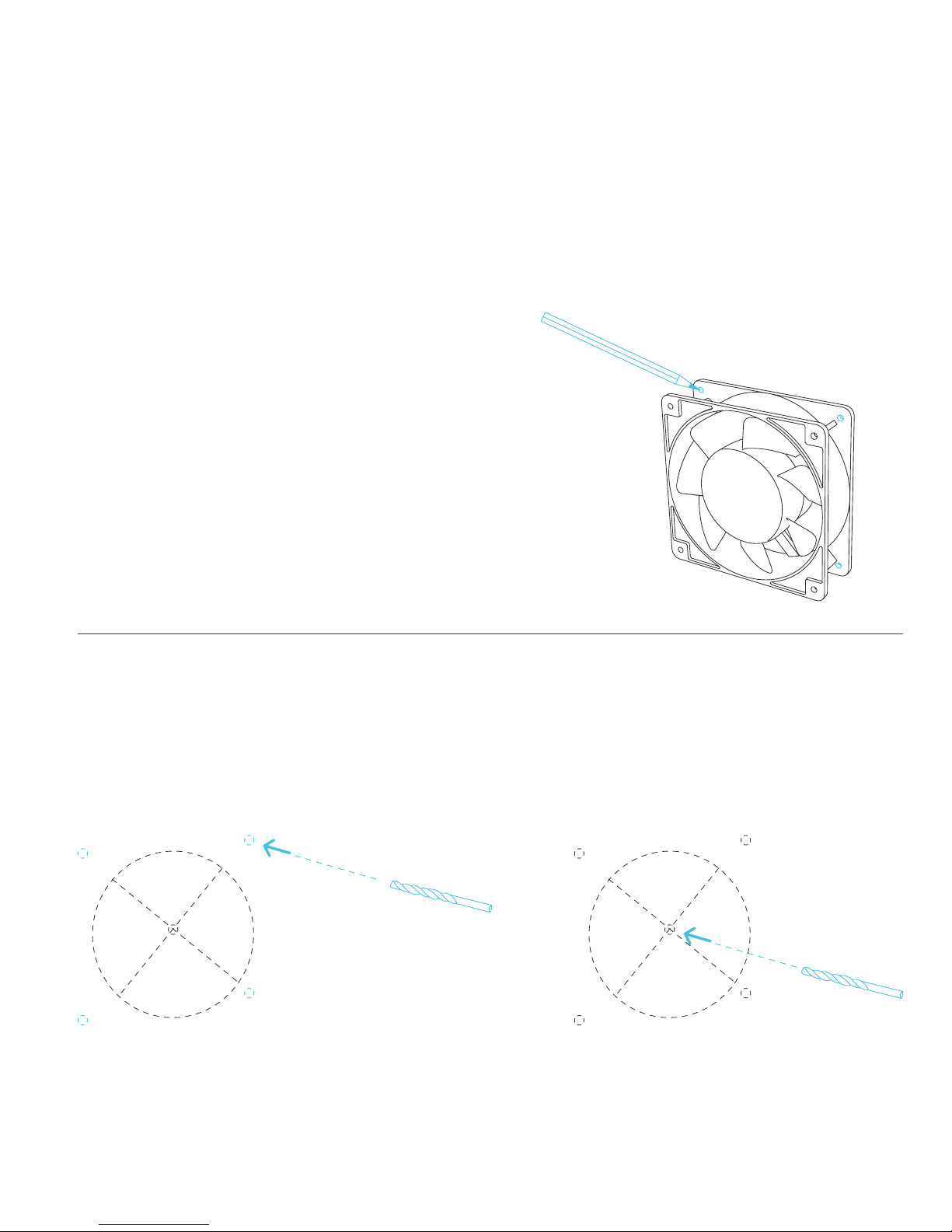
MOUNTING
STEP 1 - MARKING
Use the fan to determine the exact position where
you wish to mount it. Outline the center circle and
four outer screw holes with a pencil.
STEP 2 - DRILLING
Attach a hole saw onto the power drill, create the center hole as outlined by your markings from the
previous step. The hole saw size is dependent on the fan’s case size. Using a power drill, create
four screw holes as outlined by your markings from the previous step. We recommend using a drill
bit size from 10/64” to 14/64”.
Please see page 14 for Hinge Mounting Instructions for Speed Control Fan Kits.

13
MOUNTING
STEP 3 - POSITIONING
Position the fan against the hole just created.
Place a wire guard over the fan’s side and another
guard on the opposite end while keeping the
screw holes aligned.
STEP 4 - MOUNTING
Mount the unit using four machine screws while
holding each corresponding nut in place. Use a
screwdriver to finish tightening the unit securely.
Please see page 15 on instructions on powering
the fan.
14
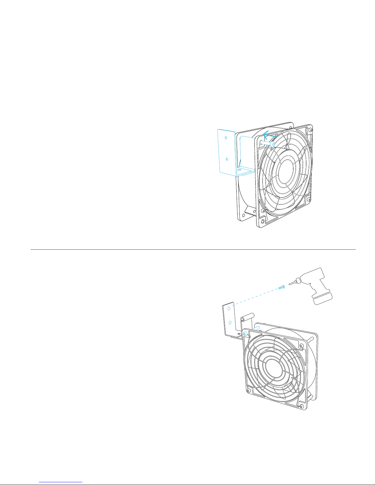
MOUNTING
STEP 1 - ATTACHING HINGE
To attach the hinge that is included in the kit, slide
the screw through the front end of the fan and the
hinge as shown. Tighten the screw appropriately.
STEP 2 - MOUNTING HINGE
To mount the hinge on to your setup, use the
included wood screw to drill into position. You may
need to turn the hinge to its side to create a clear
pathway to mount the wood screws through the
hinge and onto a surface. Please see page 15 on
instructions on powering the fan.
Hinges are only included with Speed Control Fan Kits: S1225, S1225D, S1238, and S1238D.

15
POWERING
STEP 2 - POWERING
Lastly, plug the cord’s head into a standard outlet.
You may also power the fan with a wired power
source, please see page 10 and 11.
STEP 1 - TERMINAL
After mounting your fan you can then attach the
power plug cord onto the fans terminal.

16
SPEED CONTROLLER
LIGHT INDICATOR
When the light is lit up then the speed
controller is turned on and is receiving
power. When the light is off then so is
the controller and fan.
ON
To turn on the fan, turn clockwise until
you feel a click and then keep turning
until the fan is at full power.
OFF
To completely shut off the fan, keep
turning the knob counter-clockwise until
you feel a click.
SPEED CONTROL
To adjust the fan’s speed, first turn the
knob clockwise and the fan speed will
increase gradually from low to high.
Then slowley turn it counter-clockwise
to lower the speed or to turn off the fan.
M
HL
* Controller is sold separately, only included with AXIAL S1225, S1225D, S1238 and S1238D.

17
AC INFINITY PRODUCTS
AIRPLATE SERIES
The AIRPLATE series is designed to cool home theater and audio video
cabinets. The fans are powered by USB port or power outlets. Includes an
inline speed controller and Boost Speed Adapter. The fans can also be
temperature controlled with an Advance Thermal Controller (sold separately).
AIRCOM SERIES
The AIRCOM component fan system cools receivers,
amplifiers, and other AV components. S-Series models
feature a thermal trigger and speed control. T-Series
features a LCD digital display with thermal and speed
control, alarm alerts, failure triggers, and backup memory.
PRODUCT
AIRPLATE S1
AIRPLATE S3
AIRPLATE S5
AIRPLATE S7
AIRPLATE S9
PRODUCT
AIRCOM S6
AIRCOM S7
AIRCOM S8
AIRCOM S9
AIRCOM T8
AIRCOM T9
MODEL
AI-CFS80BA
AI-CFS120BA
AI-CFD80BA
AI-CFD120BA
AI-APS9
MODEL
AI-ACS6
AI-ACS7
AI-ACS8
AI-ACS9
AI-ACT8
AI-ACT9
DIMENSIONS
4.6 x 4.6 x 1.3 in.
6.3 x 6.3 x 1.3 in.
8.4 x 4.4 x 1.3 in.
11.7 x 6.1 x 1.3 in.
17.5 x 6.1 x 1.3 in.
DIMENSIONS
11.6 x 6.3 x 1.5 in.
11.6 x 6.3 x 1.5 in.
17 x 13.5 x 1.5 in.
17 x 13.5 x 1.5 in.
17 x 13.5 x 1.5 in.
17 x 13.5 x 1.5 in.

18
WARRANTY
This warranty program is our commitment to you, the original purchaser, that each product sold
by AC Infinity will be free from defects in manufacturing for a period of two years from the date
of purchase. If a product is found to have a defect in material or workmanship, we will take the
appropriate actions defined in this warranty to resolve any issues.
The warranty program applies to any order, purchase, receipt, or use of any products from AC
Infinity. The program covers products that have become defective, malfunctioned, or expressively if
the product becomes unusable. The warranty program goes into effect on the date of purchase. The
program will expire two years from the date of purchase. If your product becomes defective during
that period, AC Infinity will replace your product with a new one or issue you a full refund.
The warranty program does not cover abuse or misuse. This includes physical damage,
submersion of the product in water, incorrect Installation such as wrong voltage input, and misuse
for any reason other than intended purposes. AC Infinity is not responsible for consequential loss or
incidental damages of any nature caused by the product. We will not warrant damage from normal
wear such as scratches and dings.
If you are not 100% satisfied with this product, we will be happy
to replace it or issue you a full refund. Please contact us!
COPYRIGHT © 2018 AC INFINITY INC. ALL RIGHTS RESERVED
No part of the materials including graphics or logos available in this booklet may be copied,
photocopied, reproduced, translated or reduced to any electronic medium or machine readable
form, in whole or in part, without specific permission from AC Infinity Inc.


www.acinnity.com
 Loading...