

Page 1

AIRTAP SERIES
REGISTER BOOSTER FAN SYSTEM
USER MANUAL
Page 2

Page 3

WELCOME
Thank you for choosing AC Infinity. We are committed to product quality and friendly customer
service. If you have any questions or suggestions, please don’t hesitate to contact us. Visit www.
acinfinity.com and click contact for our contact information.
EMAIL
support@acinfinity.com
WEB
www.acinfinity.com
LOCATION
Los Angeles, CA
3
Page 4

MANUAL CODE AT2007X1
PRODUCT
AIRTAP T4, Bronze 4” x 10”
AIRTAP T4, White 4” x 10”
AIRTAP T4, Bronze 4” x 12”
AIRTAP T4, White 4” x 12”
AIRTAP T6, Bronze 6” x 10”
AIRTAP T6, White 6” x 10”
AIRTAP T6, Bronze 6” x 12”
AIRTAP T6, White 6” x 12”
4
MODEL
AC-RBF4-B
AC-RBF4-W
AC-RBF42-B
AC-RBF42-W
AC-RBF6-B
AC-RBF6-W
AC-RBF62-B
AC-RBF62-W
UPC-A
819137020238
819137020245
819137020641
819137020658
819137020603
819137020610
819137020627
819137020634
Page 5

MANUAL INDEX
Manual Index .................................................................................
FAQ ................................................................................................
Key Features .................................................................................
Product Contents ...........................................................................
Installation. ....................................................................................
Programming .................................................................................
Other AC Infinity Products .............................................................
Warranty ........................................................................................
Page 5
Page 6
Page 7
Page 8
Page 9
Page 13
Page 21
Page 22
5
Page 6
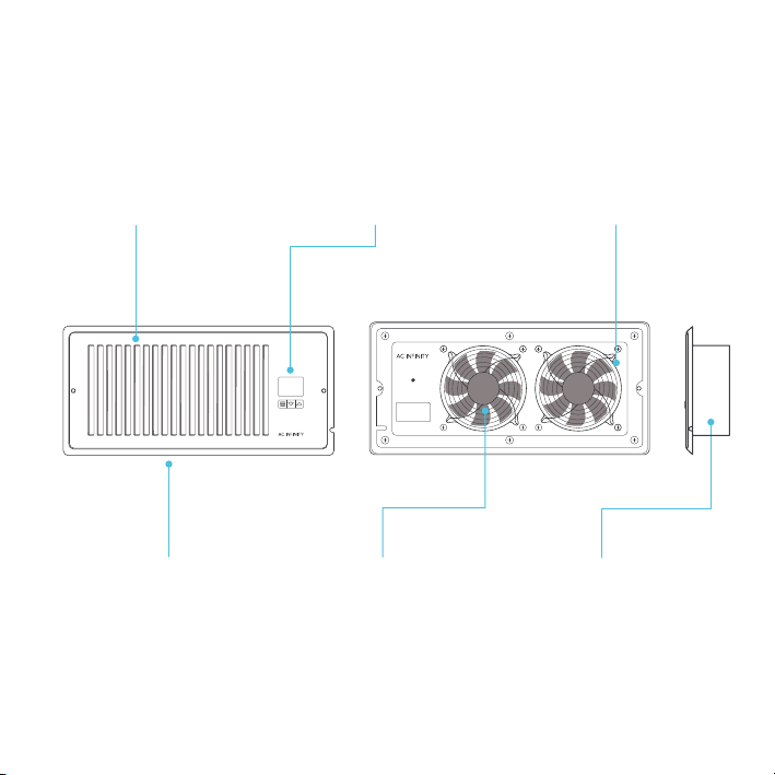
KEY FEATURES
ALUMINIUM FRAME
Features an aluminum frame
with CNC-machined corners
and a white or bronze finish to
give cabinets a clean look.
QUIET PWM MOTOR
PWM-controlled motor
features precise speed
control, reduced noise, and
energy-efficient DC power.
6
SMART CONTROLLER
Enables temperature
monitoring, hot and cold
temperature triggers, and
fan speed control.
STATOR BLADES
Hydro-mechanical stator
blades enable air to travel
farther even in high static
pressure environments.
DUAL BALL BEARINGS
Enables unit to be mounted in
any direction. Motor contains
dual-ball bearings with a
67,000 hours lifespan.
PROTECTIVE BACK
Enclosed in a thermoplastic
casing with fan guards to
protect users from high speed
fans and prevent clogging.
Page 7
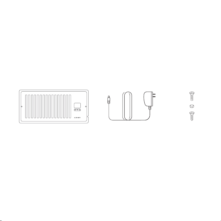
PRODUCT CONTENTS
REGISTER FAN (x1)
POWER ADAPTER (x1) SCREW SET (x2)
7
Page 8
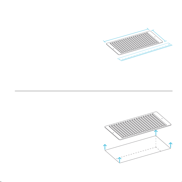
INSTALLATION
STEP 1
Measure your register vent to make sure this
model will fit. Standard sizes come in 4x10”,
4x12”, 6x10”, 6x12” etc.
STEP 2
Remove your register grille. You may need
to use a Philips screwdriver to remove the
mounting screws.
8
Page 9

INSTALLATION
STEP 3
Plug the power adapter into an outlet. This can
be next to your register or inside your register.
STEP 3.5
If you are powering the register fan with an
external outlet, run the power cord towards the
groove on the side of the register fan.
9
Page 10

INSTALLATION
STEP 4
Plug the power adapter’s cord into the power
receptacle of the register fan unit.
STEP 5
Check the LCD display to see if it is lit and
shows a number reading.
10
Page 11

INSTALLATION
STEP 6
Position the register fan to be mounted.
If the outlet is external, make sure the cord
runs through the gap between the wall and
mounting plate.
STEP 7
Drill your existing screws into the mounting
holes to secure the register fan. If needed, use
the screws included with your register fan.
If the screw holes do not align, you may need
to drill new holes into your wall.
11
Page 12

PROGRAMMING
1. MODE BUTTON
Cycles through the unit’s
modes: temperature display,
cooling trigger, heat trigger,
and fan speed.
4. COOLING TRIGGER
Allows you to set a temperature trigger for the fans to
run when your air conditioner
system is on.
12
2. UP / DOWN BUTTON
Changes the temperature
setting in the cooling trigger,
the heating trigger, and the
fan speed.
3
4 5
1 2
5. HEATING TRIGGER
Allows you to set a temperature trigger for the fans
to run when your central
heating system is on.
6
3. TEMPERATURE DISPLAY
Displays the current temperature that is measured by the
probe. Used as the default
display.
6. FAN SPEED
Sets the fans' maximum
running speed when the
cooling or heating triggers
are tripped to run.
Page 13

PROGRAMMING
IMPORTANT NOTES – PLEASE READ
This product is used to boost your existing AC or heater's airflow. It allows you to set temperature
points where the fans will turn on if the airflow's temperature falls below or rises above the cooling
or heating trigger's setting, respectively.
This product has 10 fan speeds from 1-10. Use the fan speed setting to set your desired airflow
boosting. Keep in mind the faster the fans spin, the louder they will be.
We’ve designed the fans to ramp up or down, instead of quickly turning on or shutting down to
minimize noise and power consumption.
When not changing settings, we recommend staying on the temperature display mode to monitor
and accurately gauge your airflow's temperature. Do not use your AC or heater's thermostat
reading; it does NOT display the airflow's temperature.
TEMPERATURE DISPLAY
This mode displays the airflow temperature measured by the probe.
While on this display mode, the cooling and heating triggers, as well as
the max fan speed setting, are still active unless you disabled them.
13
Page 14

PROGRAMMING
CONTROLLER LOCK
To lock the controller, go to the temperature display mode
and then hold the mode button for three or more seconds.
While the display is locked, you will not be able to switch
modes or adjust settings, but they will be working in the
background. Holding the mode button for three or more
seconds will unlock the controller.
HIDE DISPLAY
While the controller is locked, you can hide the display
and turn off its backlight by pressing the mode button.
All programs and settings will still be working in the
background while the display is hidden. Press any button
to show the display again.
NOTE: Only In Temperature Display Mode, holding the mode button will cause the display to lock!
14
Page 15

PROGRAMMING
COOLING TRIGGER
Use this mode to set the temperature trigger for your air conditioner.
Please note you are NOT setting your desired temperature.
In this mode, the fans will run if the probe temperature meets or falls
below the trigger’s cold temperature setting. It will not run if the probe
temperature is above the trigger’s cold temperature setting.
Press the up or down buttons to set the cooling trigger temperature. To
calibrate your register booster fans, turn on your AC and wait for a few
minutes until the probe temperature stabilizes. Set your cooling trigger to
this number or higher.
To avoid confusion, we recommend disabling the cooling trigger
when not using your AC. To disable it, hold the mode button for two
seconds. The display will show OF. We also recommend returning to the
temperature display mode once you finish adjusting your cooling trigger.
15
Page 16

PROGRAMMING
1 2
Your air conditioner
turns on.
3
When the probe detects the airflow
temperature has fallen below your Cooling
Trigger, it will activate the fans.
COOLING TRIGGER
If the AC is turned off, the probe
will detect a higher temperature
than your Cooling Trigger, telling
the fans to turn off.
16
Cold air blows through the
duct and into your room.
4
The fans will pull cold air from
your duct to boost your AC
Temperature you set in
Fans Running Fans Not Running
0°F 120°F
Probe Temp F/C°
output.
Cooling Trigger
Page 17

PROGRAMMING
HEATING TRIGGER
Use this mode to set the temperature trigger for your heater. Please note
you are NOT setting your desired temperature.
In this mode, the fans will run if the probe temperature meets or rises
above the trigger’s hot temperature setting. It will not run if the probe
temperature is below the trigger’s hot temperature setting.
Press the up or down buttons to set the heating trigger temperature.
To calibrate your register booster fans, turn on your heater and wait for
a few minutes until the probe temperature stabilizes. Set your heating
trigger to this number or lower.
To avoid confusion, we recommend disabling the heating trigger when
not using your heater. To disable it, hold the mode button for two
seconds. The display will show OF. We also recommend returning to the
temperature display mode once you finish adjusting your heating trigger.
17
Page 18

PROGRAMMING
1 2
Your central heating
system turns on.
3
When the probe detects the airflow
temperature has risen above your Heating
Trigger, it will activate the fans.
HEATING TRIGGER
If the heater is turned off,
the probe will detect a lower
temperature than your Heating
Trigger, telling the fans to turn off.
18
Heated air blows through the
duct and into your room.
4
The fans will pull heated air
from your duct to boost your
heater output.
Temperature you set in
Heating Trigger
Fans Not Running Fans Running
0°F 120°F
Probe Temp F/C°
Page 19

PROGRAMMING
FAN SPEED
This mode allows you to set a maximum fan
speed in which they will actively run until you
leave it. Pressing up or down will change the
fan speed and determine the level of airflow
boosting. Holding the MODE button will set the
fan speed to 0.
Keep in mind the faster the fans spin, the louder
they will be.
FAHRENHEIT OR CELSIUS
To change the temperature scale between
Fahrenheit and Celsius, hold the up and
down buttons simultaneously until the letters
change. All digits displayed will be automatically
converted to the designated scale.
19
Page 20

AIRTAP FAQ
Q: Will I be able to mount this fan on my ceiling?
A: For safety reasons, we do not recommend mounting the AIRTAP on your ceiling.
Q: Will I be able to mount this fan on a baseboard style register?
A: No. Because of the tilted design, the AIRTAP will not have the clearance to be properly mounted.
Q: My register is bigger than my fan's rear insert. How can I fit this fan onto my register?
A: We can only recommend using the appropriately sized AIRTAP fan for your register. Contact
customer service for fitment issues.
Q: Does this register booster fan have fittings to use a filter with?
A: This product is not specifically designed to be used with filters.
Q: Can I reverse this fan's airflow?
A: The AIRTAP's boosted airflow cannot be reversed, nor can the fans be flipped.
Q: What temperature is the register booster fan detecting?
A: The AIRTAP's backside probe reads the airflow temperature of your register vent. Please note
this temperature may vary from your home thermostat's reading.
Q: My register booster fan is too loud. How do I decrease the fan noise?
A: To minimize the noise coming from the AIRTAP, decrease the maximum fan speed. Refer to
page 19.
Q: My fan is constantly running when I don't need it to. How do I turn it off?
A: The heating and cooling triggers may be active at the same time. Disable the trigger you are not
using by holding the mode button until the screen displays OF.
20
Page 21

AC INFINITY PRODUCTS
RACK FANS
The CLOUDPLATE series rack fan system is designed for quietly
cooling a wide range of audio, video, home theater, network, and
IT equipments racks. The model features a thermal controller
with intelligent programming that will automatically adjust the
fan speeds in response to changing temperatures.
DUCT FANS
The CLOUDLINE series is a line of duct fans designed to quietly
ventilate AV rooms and closets, as well as various DIY air circulation
and exhaust projects. Features a thermal controller with intelligent
programming that will automatically adjust duct fan speeds in
response to changing temperatures.
PROJECT MUFFIN FANS
The AXIAL series fan kit is designed for various DIY projects
that requires cooling or ventilation; or as a replacement fan for
many products on the market. Each fan kit includes fan guards
and everything needed to mount the unit onto a wall and power it
through a wall outlet. S-series models include a speed controller.
Discover the latest innovations in cooling and ventilation at acinfinity.com
21
Page 22

WARRANTY
This warranty program is our commitment to you, the product sold by AC Infinity will be free from
defects in manufacturing for a period of two years from the date of purchase. If a product is found
to have a defect in material or workmanship, we will take the appropriate actions defined in this
warranty to resolve any issues.
The warranty program applies to any order, purchase, receipt, or use of any products sold by AC
Infinity or our authorized dealerships. The program covers products that have become defective,
malfunctioned, or expressively if the product becomes unusable. The warranty program goes into
effect on the date of purchase. The program will expire two years from the date of purchase. If your
product becomes defective during that period, AC Infinity will replace your product with a new one
or issue you a full refund.
The warranty program does not cover abuse or misuse. This includes physical damage,
submersion of the product in water, incorrect Installation such as wrong voltage input, and misuse
for any reason other than intended purposes. AC Infinity is not responsible for consequential loss or
incidental damages of any nature caused by the product. We will not warrant damage from normal
wear such as scratches and dings.
To initiate a product warranty claim, please contact our customer service team at
support@acinfinity.com
If you have any issues with this product, contact us and we’ll
happily resolve your problem or issue a full refund!
Page 23

COPYRIGHT © 2021 AC INFINITY INC. ALL RIGHTS RESERVED
No part of the materials including graphics or logos available in this booklet may be
copied, photocopied, reproduced, translated or reduced to any electronic medium or
machine readable form, in whole or in part, without specific permission from AC Infinity Inc.
Page 24

 Loading...