


AIRCOM SERIES
COMPONENT COOLING SYSTEM
USER MANUALUSER MANUAL


WELCOME
Thank you for choosing AC Infinity. We are committed to product quality and friendly customer service.
If you have any questions or suggestions, please don’t hesitate to contact us. Visit www.acinfinity.com
and click contact for our contact information.
EMAIL
support@acinfinity.com
WEB
www.acinfinity.com
LOCATION
Los Angeles, CA
3

MANUAL CODE AC2007X1
PRODUCT
AIRCOM S6
AIRCOM S7
AIRCOM S8
AIRCOM S9
AIRCOM S10
AIRCOM T8
AIRCOM T9
AIRCOM T10
4
MODEL
AI-ACS6
AI-ACS7
AI-ACS8
AI-ACS9
AC-ACS10
AI-ACT8
AI-ACT9
AC-ACT10
UPC-A
854759004624
854759004631
854759004648
854759004655
819137020320
854759004662
854759004679
819137020313

MANUAL INDEX
Manual Index .................................................................................
Product Requirements ...................................................................
Key Features .................................................................................
Product Contents ...........................................................................
Product Setup ................................................................................
Programming (S6, S7, S8, S9, S10)...............................................
Programming (T8, T9, T10)............................................................
FAQ ................................................................................................
Other AC Infinity Products .............................................................
Warranty ........................................................................................
Page 5
Page 6
Page 7
Page 9
Page 10
Page 12
Page 14
Page 20
Page 21
Page 22
5
PRODUCT REQUIREMENTS
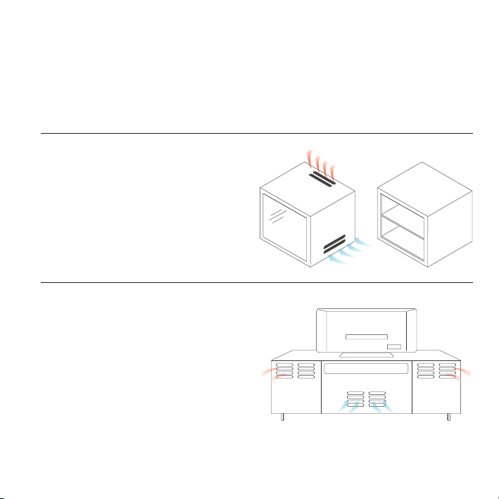
The AIRCOM series is designed to cool various AV components by accelerating the intake of cool
air and outtake of heat. Please make sure that the following requirements are met to ensure the
cooling system will work effectively.
FULLY ENCLOSED CABINETS
The cooling system is not compatible with fully
enclosed cabinets. Air must be able to travel in
and out of the cabinet. Please make sure that
your cabinet has ventilation holes or is open at
the front or back.
REAR EXHAUST MODELS
For models containing blowers, AIRCOM
S6, S8, and T8, the cabinet’s ventilation
holes should be at the rear. The hot air that
the cooling system is exhausting should be
directed out of the cabinet through its rear
holes.
6
PRODUCT REQUIREMENTS
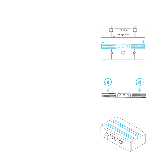
WEIGHT LIMITATIONS
AIRCOM S6, and S7 can support a top weight limit
of 10 pounds. AIRCOM S8, S9, S10, T8, T9 and
T10 can support a top weight limit of 30 pounds.
Please make sure that the component does not
block the cooling system cooling system’s vents.
OPERATION LIMITATIONS
The fan system has an operating temperature
rating of 32° F to 140° F and a humidity rating
of 35% to 85% RH. Please make sure that the
system’s environment does not exceed these
parameters.
COMPONENT VENTS
The cooling system is designed to be placed on
top of AV components to draw out hot air upwards
or at the rear. The system works more effectively if
the AV component has vents at the top.
7
KEY FEATURES
STEEL ENCLOSURE
Cold-rolled steel enclosure
enables additional AV
components to be stacked
on top of the cooling system.
EXPANDABLE PORTS*
AIRPLATE and MULTIFAN
fans can be plugged into the
unit to share temperature and
fan speed settings.
8
NOISE REDUCTION
New and improved noise
reduction using gaskets that
absorbs noise caused by the
fan’s vibrations.
ULTRA-QUIET FANS
Fans are designed to
maximize airflow CFM to
noise dBA ratio. Contains
long life dual-ball bearings.
S SERIES CONTROLLER
Features fan speed control
and a pre-set temperature
trigger that turns the fans on
at 88° F and off at 84° F.
T SERIES CONTROLLER*
LCD display enables active
temperature monitoring,
thermal control, speed control,
and SMART energy mode.
* Available only on AIRCOM T8 and T9

PRODUCT CONTENTS
AIRCOM S6
AIRCOM S7
COOLING FAN SYSTEM (x1)
AIRCOM S8
AIRCOM S9
AIRCOM S10
COOLING FAN SYSTEM (x1)
AIRCOM T8
AIRCOM T9
AIRCOM T10
COOLING FAN SYSTEM (x1)
AI-ACS6
AI-ACS7
AI-ACS8
AI-ACS9
AC-ACS10
AI-ACT8
AI-ACT9
AC-ACT10
POWER ADAPTER (x1)
POWER ADAPTER (x1)
POWER ADAPTER (x1)
9

PRODUCT SETUP
STEP 1
Insert the AC plug of your power adapter into a
power outlet.
STEP 2
Plug the male connector of the adapter into the
female connector located on the backside of the
cooling fan system.
10

PRODUCT SETUP
STEP 3
Place the cooling fan system on top of your AV
component.
STEP 4
Set up the cooling fan system’s temperature
and speed settings on the control module.
Refer below to see the model and instructions
to follow.
AIRCOM S6, S7, S8, S9, S10
Please refer to Page 12 for instructions.
AIRCOM T8, T9, T10
Please refer to Page 14 for instructions.
11

PROGRAMMING
AIRCOM S6 S7 S8 S9 S10
MODE CONTROL BUTTON
Pressing this button will cycle through
the modes: ON Mode, AUTO Mode,
SMART Mode, OFF Mode.
AUTO MODE LIGHT
This orange light indicates
if the system is running in
AUTO Mode.
SMART AND OFF MODE LIGHT
Both the orange and white light will be visible when the controller is in SMART Mode. When both
lights are not visible, the controller is in OFF Mode.
FAN SPEED LIGHT OPTIONS
The fan speed light displays the current speed of the fan. However, the light can also be set to
become invisible automatically when you are not changing the speed settings. Holding the mode
control button for three seconds will alternate between these two setting options.
12
FAN SPEED LIGHT
Indicates fan speed; and
also the speed settings of
AUTO and SMART Mode.
SPEED CONTROL BUTTON
Pressing this button changes the speed
settings while the fans are running in
ON, AUTO, and SMART Mode.
ON MODE LIGHT
This white light indicates if
the system is running in ON
Mode.

PROGRAMMING
AIRCOM S6 S7 S8 S9 S10
MODE CONTROL
Pressing the Mode Control button will cycle through the operating modes: ON
Mode, AUTO Mode, SMART Mode and OFF Mode.
ON MODE - A white light as shown on page 12 indicates if the system is running in
ON Mode. In this mode, the fans will run continuously regardless of temperature.
AUTO MODE - An orange light as shown on page 12 indicates if the system is
running in AUTO Mode. In this mode, the fans will only be triggered to run when
the temperature is at 88° F or higher. While running, the fans will turn off when the
temperature is at 84° F or lower.
SMART MODE - Both the orange and white light will be visible to indicate if the
system is running in SMART Mode. In this mode the fans will change speed
depending on the measured temperature. For every 2° F increment that the
temperature is below 88° F, the speed of the fans will decrease by one level.
OFF MODE - In this mode, the white and orange light will not be visible; and the
fans will not run regardless of temperature.
SPEED CONTROL
While in ON, AUTO, or SMART Mode, you can press this button to change the
speed settings. In ON Mode, you can set what speed the fans will run continuously
at. In AUTO Mode, pressing this button will set what speed the fans will run at when
they are triggered to run. In SMART Mode, the speed you set will be the highest
speed the fans can reach at 88° F; and drop by one level for every 2° F decrease.
13

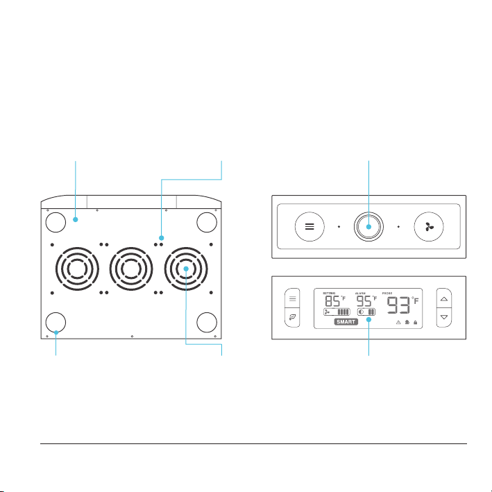
PROGRAMMING
AIRCOM T8 T9 T10
1. MODE BUTTON
Cycles through the unit’s
modes: AUTO, SMART, OFF,
ON, ALARM. Holding for
three seconds will lock or
unlock the display.
1
3
4. SETTING TEMP
Shows the temperature you
set the fans to trigger in
AUTO and SMART Mode.
7. FAN SPEED
Shows what speed the fans
are currently running at. Six
speeds are available.
14
2. UP / DOWN BUTTON
The up and down buttons
changes the setting
temp, alarm temp, display
brightness, or the speed of
the fan.
4 5 6
7 8
5. ALARM TEMP
Shows the temperature
that you set the fan’s alarm
system to trigger.
8. BRIGHTNESS
Shows the brightness of
the display. Four settings
are available.
3. LEAF BUTTON
This turns the display off
while programs run in
the background. Holding
will change degrees to
Fahrenheit or Celsius.
2
9
6. PROBE TEMP
Actively shows current
temperature that the probe
is measuring.
9. ALERT ICONS
Flashes to indicate if check
fan alert, or display lock is
being triggered.

PROGRAMMING
AIRCOM T8 T9 T10
QUICK START
Press the MODE button until you are on AUTO mode. This mode works like a thermostat. Then
press the up and down triangle buttons to change the SETTING temperature on the screen. The
PROBE temperature is what the thermal probe is measuring. When the PROBE temperature
exceeds the SETTING temperature, the fans will start running.
ON MODE
In this mode, the fans will run non-stop regardless of
temperature. Pressing the up and down buttons while in this
mode will change the speed of the fan. Whichever speed is
designated in this mode will also be the speed used in AUTO
Mode and the max speed of the fans in SMART Mode.
AUTO MODE
This is the thermostat setting where the fans will start running
when the PROBE temperature reaches or surpasses the
SETTING temperature. The SETTING temperature can be
designated by pressing the up and down buttons while in this
mode. Once the fans start running, the PROBE temperature
would need to fall at least 4° F below the SETTING temp for
the fans to stop running. This variation buffer can be changed
to 2° F, see page 18 for more information.
15

PROGRAMMING
AIRCOM T8 T9 T10
OFF MODE
In this mode, the fans are powered off regardless of set
temperature or set speed. The backlight setting can be
increased or decreased by pressing the up or down buttons
while in this mode. If the first and the third brightness bar
light up and the device is left unattended for 30 seconds,
the display will automatically dim its brightness back to the
dimmest setting.
SMART MODE
This is the energy saving mode where the fans will change
speed depending on the temperature. The SETTING
temperature can be designated by pressing the up and down
triangle buttons while in this mode.
For every 4°F increment that the PROBE temperature is
below the SETTING temperature, the speed of the fans will
decrease by one level. This increment can be changed to
2°F, please see page 18 for more information.
The fan speed you designated in ON Mode will also be
the max speed the fan’s can reach. This occurs when the
PROBE temperature reaches or exceeds the SETTING
temperature.
16

PROGRAMMING
AIRCOM T8 T9 T10
ALARM SETTING
In this mode, you can set what temperature the
system’s alarm will trigger by pressing the up
and down triangle buttons. When the PROBE
temperature reaches or exceeds the ALARM
temperature, the alarm will activate. The alarm will
only activate while the controller is in ON, AUTO, or
SMART Mode so please remember to exit ALARM
Mode once the alarm has been set.
When the alarm is triggered, the fan will run at max
speed regardless of mode and will make an audible
beep every three seconds. This will keep occurring
until the temperature drops below the ALARM temp
or if any buttons are pressed.
The alarm can be disabled to not trigger
by pressing the up triangle button until the
temperature is at 140° F, then pressing the up
button once more to show “OF”.
FAHRENHEIT OR CELSIUS
The temperatures displayed can be set to Fahrenheit or Celsius scale by holding the LEAF button
until °F or °C is shown after the digits. All digits displayed will be automatically converted to the
designated scale.
ALARM
17

PROGRAMMING
AIRCOM T8 T9 T10
VARIATION BUFFER
In AUTO mode, a buffer is built in to prevent your fan from turning on and off too quickly due
to small variations in the environment. When the PROBE temperature exceeds your SETTING
temperature, the fan will start running immediately. However, the PROBE temperature will need to
fall below your SETTING temperature by 4° Fahrenheit or 2° Celsius or more, to stop the fans from
running. In SMART mode, the speed of the fan will decrease by one level for every 4° Fahrenheit or
2° Celsius that the PROBE temperature is below the SETTING temperature.
To change this buffer or increment setting to 2° Fahrenheit or 1° Celsius, hold the MODE button
and DOWN button together for three seconds. To change back to 4° Fahrenheit or 2° Celsius, hold
the MODE button and UP button together for three seconds.
CONTROLLER LOCK
Holding the MODE button for three or more seconds will lock the controller. The controller will still
work as programmed. However, pressing any buttons will not have an effect and will cause the
screen lock icon to flash. This option was designed to prevent your controller settings from being
changed by accident. Holding the MODE button again for three or more seconds will unlock the
controller.
CONNECTING MORE FANS
On the backside of the AIRCOM T8, T9, and T10 models, there
are two USB ports. Up to six MULTIFAN or AIRPLATE fans can
be plugged into it to share the same programming. A model
can contain more than one fan. For example, an AIRPLATE S7
contains two fans so only three AIRPLATE S7s are supported.
Before daisy chain one more fan, please make sure the
previous fan speed is set on High speed. Please see page 20
for more information.
18

PROGRAMMING
AIRCOM T8 T9 T10
ALERT ICONS
On the bottom right of the display there are three alert icons. They are visible to show that the
system’s functions are being monitored. They will flash when the controller wishes to alert you that
a particular function is being triggered.
CHECK FAN ALERT
The check fan icon will flash when the fan’s sensor detects interference to
its operation. Please check the fan for possible issues. If the fan is rotating, it
may just be static pressure resistance and operating as intended. If the fan is
not rotating, please see the warranty page for replacement information.
ALARM ALERT
The alarm alert icon will flash when the probe temperature reaches or
exceeds the alarm temperature you have set. Please see page 17 for more
information on setting up the alarm.
DISPLAY LOCK ALERT
This icon is not visible when the controller is unlocked. The icon will flash
when any buttons are pressed while the controller is locked. To lock or unlock
the controller, hold down the MODE button for three or more seconds.
19

AIRCOM FAQ
Q: Is this fan capable of being rack mounted?
A: This fan is not specifically designed to be mounted in rack cabinets.
Q: How many fans can I connect to the expansion USB ports?
A: You may connect up to two MULTIFANs per USB por t. This feature is only available in the
AIRCOM T-Series.
Q: What is the biggest load I can stack on top of the AIRCOM?
A: 12” models can take up to 10 pounds of electronics and equipment on top of it. 17” models can
take up to 30 pounds.
Q: How do I clean the fan blades?
A: Use compressed air to clear dust from the fans during maintenance. Do not disassemble the
AIRCOM to dust the fans.
Q: Can I use the AIRCOM as a laptop cooler?
A: This product is not designed to be used as a laptop cooler. The fans cannot be flipped to create
intake airflow instead of exhaust airflow.
Q: Will I be able to use this fan upside down?
A: We do not recommend flipping the unit upside down. The unit may not sit in place and would be
in danger of slipping if placed a few feet from the ground.
20

AC INFINITY PRODUCTS
AIRPLATE SERIES
The AIRPLATE series is designed to cool home theater and audio video
cabinets. The fans are powered by USB port or power outlets. Includes an
inline speed controller and Boost Speed Adapter. The fans can also be
temperature controlled with an Advance Thermal Controller (sold separately).
PRODUCT
AIRPLATE S1
AIRPLATE S3
AIRPLATE S5
AIRPLATE S7
AIRPLATE S9
MULTIFAN SERIES
The MULTIFAN series fans can be placed on top of AV components and
electronics to exhaust hot air economically. It features an inline speed
controller and can be powered by an USB port. The fans can also be powered
through a power outlet with a Boost Speed Adapter (sold separately).
PRODUCT
MULTIFAN S1
MULTIFAN S3
MULTIFAN S4
MULTIFAN S5
MULTIFAN S7
MODEL
AI-CFS80BA
AI-CFS120BA
AI-CFD80BA
AI-CFD120BA
AI-APS9
MODEL
AI-MPF80A
AI-MPF120A
AI-MPF140A
AI-MPF80A2
AI-MPF120A2
DIMENSIONS
4.6 x 4.6 x 1.3 in.
6.3 x 6.3 x 1.3 in.
8.4 x 4.4 x 1.3 in.
11.7 x 6.1 x 1.3 in.
17.5 x 6.1 x 1.3 in.
DIMENSIONS
3.1 x 3.1 x 1 in.
4.7 x 4.7 x 1 in.
5.5 x 5.5 x 1 in.
3.1 x 3.1 x 1 in. /fan
4.7 x 4.7 x 1 in. /fan
21

WARRANTY
This warranty program is our commitment to you, the product sold by AC Infinity will be free from
defects in manufacturing for a period of two years from the date of purchase. If a product is found
to have a defect in material or workmanship, we will take the appropriate actions defined in this
warranty to resolve any issues.
The warranty program applies to any order, purchase, receipt, or use of any products sold by AC
Infinity or our authorized dealerships. The program covers products that have become defective,
malfunctioned, or expressively if the product becomes unusable. The warranty program goes into
effect on the date of purchase. The program will expire two years from the date of purchase. If your
product becomes defective during that period, AC Infinity will replace your product with a new one
or issue you a full refund.
The warranty program does not cover abuse or misuse. This includes physical damage,
submersion of the product in water, incorrect Installation such as wrong voltage input, and misuse
for any reason other than intended purposes. AC Infinity is not responsible for consequential loss
or incidental damages of any nature caused by the product. We will not warrant damage from
normal wear such as scratches and dings.
For more information about our dealers and distributors, please contact our customer service at
support@acinfinity.com or (626) 923-6399 Monday to Friday (9:00 am to 5:00 pm PST).
If you have any issues with this product, contact us and we’ll
happily resolve your problem or issue a full refund!

COPYRIGHT © 2021 AC INFINITY INC. ALL RIGHTS RESERVED
No part of the materials including graphics or logos available in this booklet may be
copied, photocopied, reproduced, translated or reduced to any electronic medium or
machine readable form, in whole or in part, without specific permission from AC Infinity Inc.

 Loading...