

Page 1
WPR2 Series (Max. Line Pressure < 300 PSI)
Installation and Operation Instructions
Wet to Wet Differential Pressure
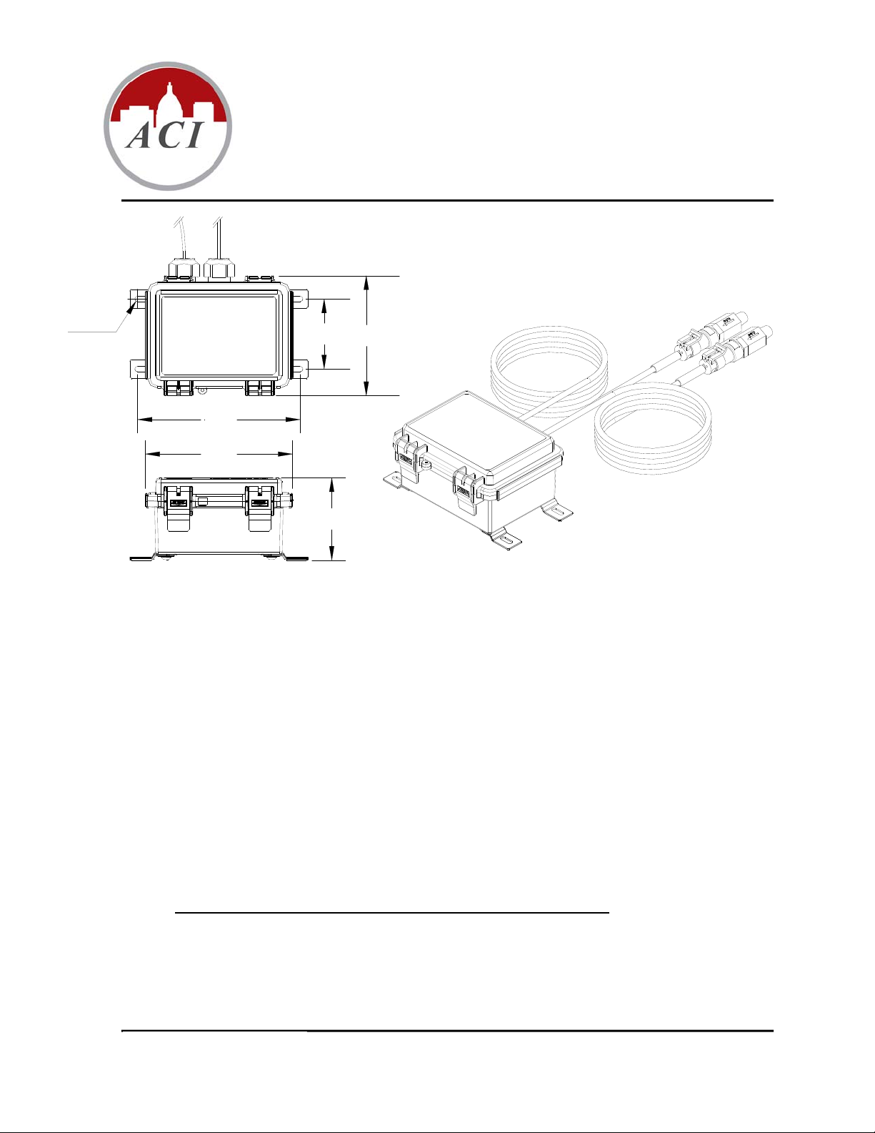
Ø0.200"
2.60"
4.47"
5.47"
5.28"
3.00"
Figure 1: WPR2 Dimensions and Hardware
Precautions
REMOVE POWER BEFORE WIRING. NEVER CONNECT OR DISCONNECT WIRING WITH THE
POWER APPLIED. DO NOT ALLOW LIVE WIRES TO TOUCH THE CIRCUIT BOARD.
AN
ISOLATION TRANSFORMER IS RECOMMENDED WHEN POWERING THE DEVICE WITH
24VAC.
DO
FAILURE
DO
DO
DO
NOT RUN THE WIRING IN ANY CONDUIT WITH LINE VOLTAGE.
TO
WIRE DEVICES WITH THE CORRECT POLARITY WHEN USING A SHARED
TRANSFORMER MAY RESULT IN DAMAGE TO ANY DEVICE POWERED BY THE SHARED
TRANSFORMER.
NOT SWITCH PRESSURE RANGE AND OUTPUT MODE WHEN POWER IS ON. MAKE SURE TO
POWER OFF THE UNIT FIRST, THEN MOVE JUMPERS TO THE RIGHT POSITIONS AND THEN
POWER ON THE TRANSMITTER.
NOT APPLY ANY EXTERNAL VOLTAGE TO ZERO TERMINALS.
NOT REPLACE PRESSURE SENSORS WITH ANY OTHER SENSORS. DO NOT INTERCHANGE
THE HIGH AND LOW SENSORS. THE HIGH AND LOW SENSORS ARE SPECIFICALLY
CALIBRATED TO THE WPR2 UNIT.
CHANGES TO THE SENSORS WILL VOID THE PRODUCT WARRANTY
ANY
I0000756
Page 1 of 5
Version : 17.0
Page 2
T
T
T
Wiring
Shielded cable with 16 to 22AWG conductors is recommended. Each WPR2 unit can be configured to three
output modes: 4-20mA, 0-5V and 0-10V. Use the Wiring Connections table below to determine the proper
wiring for your application. See Figure 1 below for Output Mode and Output Signal switch positions.
Note: The WPR2 units are shipped from the factory set up with a 0-10 VDC output.
Output Mode
(SW8)
Vout 0-5 VDC (5V) VAC/VDC V+ COM VOU
Vout 0-10 VDC (10V) VAC/VDC V+ COM VOU
mA 4-20 mA VDC V+ IOU
Output Signal
(SW7 Position 2)
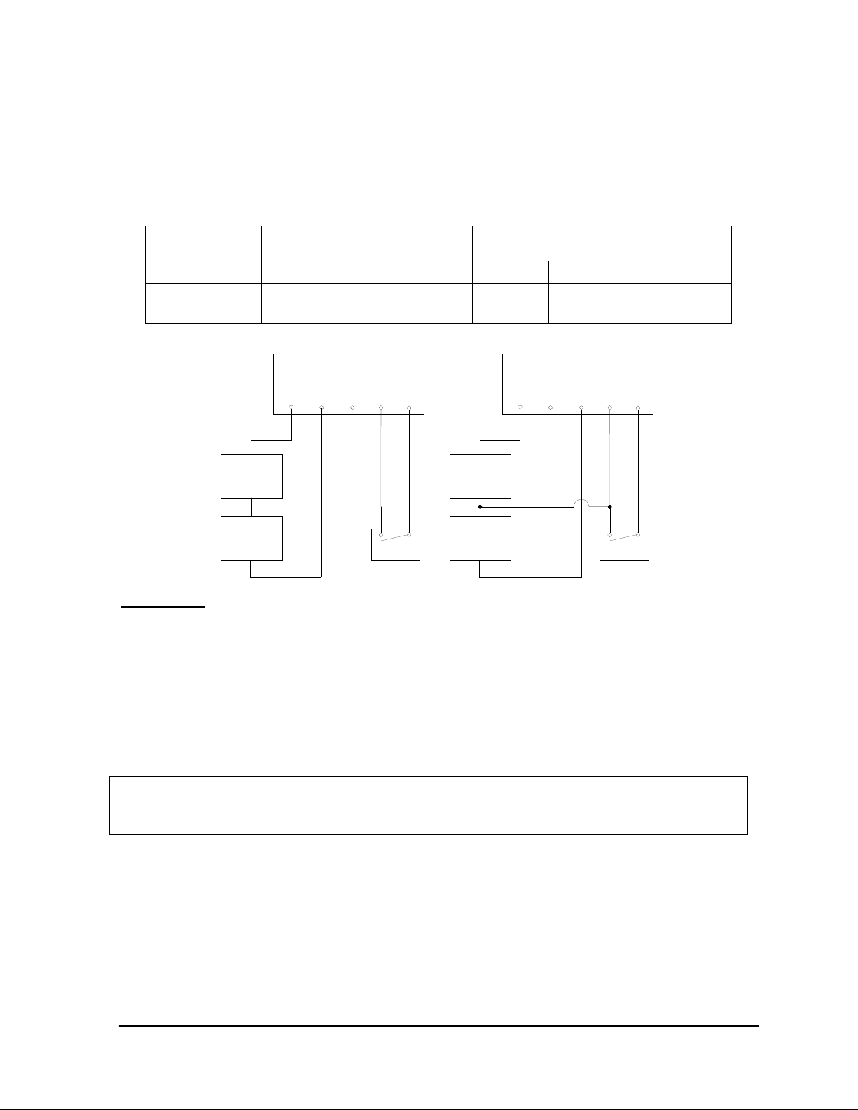
Table 1: Wiring Connections
WPR2 Terminals
Supply
Voltage
Wire Connections
WPR2 Terminals
V+
IOUT VOUT
+
Com
Com
+
COM
ZERO
Relay
+
VDC
Power Supply
Com
Com
Current
Meter
+
V+
IOUT VOUT
COM
Relay
ZERO
VDC/VAC
Power Supply
Voltage
Meter
AUTO ZERO
The WPR2 unit should be “ZEROED” before the pressure transducers are installed on the pipes.
The Auto zero button and remote zero are both used to cancel out the offsets caused by installation and sensor
drift.
NOTE: Make sure a minimum of 10 minutes of warm-up time before adjustment to the ZERO.
The Auto Zero adjustment should only be performed with NO pressure applied to both sensors.
Shut off your main pressure valve and open a shutoff valve with hose drain to equalize the pressure in
the line to your atmosphere.
Remove the sensors from the system to remove pressure from each sensor to achieve equal pressure.
Push “ZERO” button or “SHORT ZERO PIN” for 2 seconds to “COM PIN” before installation or
when it is necessary.
For units with LCD display:
“ZERO” icon will be on when the push button is released. If auto zero is successful, “ZERO” icon will flash
twice, otherwise “ERROR” and “OVR” icons will flash twice.
Pressure Connections
The WPR2 Series have 1/4"-18NPT male fittings. The sensors are labeled “SENSOR HIGH” and “SENSOR
LOW”; MAKE SURE THE SENSORS ARE WIRED TO THE CORRESPONDING TERMINAL
BLOCK INSIDE THE HOUSING. Otherwise ACI will not guarantee the accuracy specifications. DO NOT
REPLACE SENSORS WITH ANY OTHER SENSORS. THE WPR2 UNITS ARE CALIBRATED WITH
THE HIGH AND LOW SENSORS SUPPLIED WITH THE UNIT.
All WPR2 units can handle a proof pressure of 3X THE MAXIMUM LINE PRESSURE for both HIGH and
LOW pressure sensors. If after connecting the pipe, the unit outputs out-of-range signal OVR on display only,
I0000756
Page 2 of 5
Version : 17.0
Page 3

turn off the unit, disconnect the pipe or s
hut down the valves immediately and check the pressure input with a
gauge or other test instrument.
A Pressure Snubber is included with each sensor to dampen pressure surges. A pigtail siphon should be used to
lower the media temperature below 230°F (110°C) to prevent damage to the pressure sensor.
ACI/WPR2
Installation
Supply Voltage & Control Signal
Pressure Snubber
Supplied by ACI
Shut Off Valve
Supply Water Line (60 PSI)
INPUT RANGE ADJUSTMENT
DO NOT SWITCH PRESSURE RANGE AND OUTPUT MODE WHEN POWER IS ON.
MAKE SURE POWER TO THE UNIT IS OFF. FAILURE TO DO SO WILL NOT ALLOW ANY NEW
o
SWITCH SETTINGS TO TAKE PLACE.
C
HOOSE DIFFERENTIAL RANGE BASED ON THE EXPECTED DIFFERENTIAL PRESSURE IN YOUR
APPLICATION
MOVE SWITCHES TO THE CORRECT POSITIONS AND THEN POWER ON THE TRANSMITTER.
o
Pressure
Transducer
Direction of
Water Flow
.
WPR2
Power High
Pump
Low
Pressure Snubber
Supplied by ACI
Shut Off Valve
Return Water Line (55 PSI)
Direction of
Water Flow
Pressure
Transducer
MAXIMUM
LINE PRESSURE
ACI/Part No. Maximum Line Pressure
WPR2-30 30 PSI
WPR2-100 100 PSI
The WPR2 can operate in either unidirectional mode (0 – X PSI) or bidirectional mode (± X PSI). The unit will
set at unidirectional mode after factory calibration.
Unidirectional Mode
DIP switch SW7 position 1 set at UNI side.
DIP switch SW7 positions 4 and 5 are for Range Selection
ACI/Part No.
SW7 Position 5: 1 SW7 Position 5: 2
Position 4: A Position 4: B Position 4: A Position 4: B
A/WPR2-30 0-30 PSI 0-15 PSI 0-7.5 PSI 0-3 PSI
A/WPR2-100 0-100 PSI 0-50 PSI 0-25 PSI 0-10 PSI
Bidirectional Mode
DIP switch SW7 position 1 set at BI side.
DIP switch SW7 positions 4 and 5 are for Range Selection
I0000756
Page 3 of 5
Version : 17.0
Page 4

Note: In Bidirectional mode, a valu
e of 0 PSID will have an output equal to 50% of the full output range.
ACI/Part No.
SW7 Position 5: 1 SW7 Position 5: 2
Position 4: A Position 4: B Position 4: A Position 4: B
A/WPR2-30
A/WPR2-100
±30 PSI ±15 PSI ±7.5 PSI ±3 PSI
±100 PSI ±50 PSI ±25 PSI ±10 PSI
5
4
3
2
1
ON
Figure 1
ENGINEERING UNITS ADJUSTMENT
This option is ONLY for units with LCD display. Switch DIP switch SW7 position 3 to select PSI or BAR.
Advanced Features
For units with LCD display:
“ERROR” icon will be on when differential pressure is out of range.
“OVR” icon will be on when gage pressure is out of range on either the high or low port.
Trouble Shooting
Problem Trouble Shooting Steps
“ERROR” icon on Display will be on
when differential pressure is out of range.
The differential pressure could be lower or
higher than the selected range.
“OVR” icon on Display will be on when
the input pressure is > than Max Line
Pressure. Check pressure input with a
gauge or other test instrument. The
WPR2-300 Series is available for
pressures over 100 PSI.
Output reading @ 4mA or 0 VDC
all the time
1. Verify the HIGH Sensor Voltage is between
0.5 VDC (0 PSI) and 4.5 VDC (Max. Line Pressure)
When measuring from the HIGH Sensor terminal
Block “GND” to “OUT”. If out of range call ACI for
Technical support.
2. Verify the LOW Sensor Voltage is between
0.5 VDC (0 PSI) and 4.5 VDC (Max. Line Pressure)
When measuring from the LOW Sensor terminal
Block “GND” to “OUT”. If out of range call ACI for
Technical support.
3. Verify in Uni-Directional Mode that the HIGH Sensor
Voltage is ≥ the LOW Sensor Voltage. If voltage is
anything different call ACI for Technical support.
1. Verify proper Supply Voltage at the transducer meets the
Product Specifications.
2. Verify 5 VDC Reference voltage across “VIN” to “GND”
terminals for both the HIGH & LOW Sensor
terminal blocks. If voltage is anything different than
5VDC call ACI for Technical support.
Erroneous Readings 1. Bleed Air from System.
2. Repeat the Auto Zero calibration on page 2.
Version : 17.0
I0000756
Page 4 of 5
Page 5

Product Specifications
Supply Voltage 4-20mA Output: 250 Ohm Load 16-36 VDC
4-20mA Output: 500 Ohm Load 20-36 VDC
0-5 VDC Output: 16-36 VDC / 24VAC (+/-10%)
0-10 VDC Output: 16-36 VDC / 24VAC (+/-10%)
Supply Current 24mA minimum
Output 2-wire, 4 to 20mA DC Current (500 Ohm Load Max.)
or 3-wire, 0-5 or 0-10VDC (5K Ohm Min.)
Sensor Accuracy1 +/- 1.5% FSO for 0-10PSI and 0-30PSI ranges
+/- 1% FSO for all other ranges
Output Update Rate 1 Second Interval
Response Time (0-100%) 8 Seconds
Operating Temperature Range Sensor: -40 to 230°F (-40 to 110°C)
Enclosure: 5 to 176°F(-15 to 80°C)
Sensor Cable: 0 to +75°C (32 to 167°F)
Compensated Temperature Range 32 to 140°F (0 to 60°C)
Humidity 10 to 90% RH, non-condensing
Thermal Effects2 +/-2%FSO (0 to 60°C)
Proof Pressure 3 x F.S. for WPR2 Series
Burst Pressure 1500 PSI
Media Gases, refrigerants, ammonia and water-based fluids *
Features Depluggable terminal blocks
Push button/Remote Auto Zero
DIP switch selectable ranges and output modes
Out-Of-Range Diagnostic Output
Enclosure IP66 Rated (Mounting Flanges & Screws Included)
Approvals RoHS
Display Optional LCD display
Note 1: Accuracy includes linearity,
hysteresis and repeatability.
Note 2: Shift is relative to 77°F
(25°C).
*Please contact ACI for petrol chemical compatible versions.
Table 2: Product Specifications
Warranty Specification
The ACI WPR2 Series is covered by ACI’s Five (5) Year Limited Warranty, which is located in the front of
ACI’S SENSORS & TRANSMITTERS CATALOG or can be found on ACI’s web site:
Version : 17.0
I0000756
Page 5 of 5
 Loading...