

Page 1
GENERAL INFORMATION
The RH Duct and Outside transmitter is a Relative
Humidity transmitter that can be powered with either an
AC or DC supply voltage. The transmitter can also
include an optional temperature sensor for monitoring
the space temperature.
All units are shipped from the factory set up with a 4-20
mA output. The RH Duct and Outside transmitter is
field selectable with a 4-20 mA, 0-5 VDC, or 0-10 VDC
output signal that is equivalent to 0 to 100% RH.
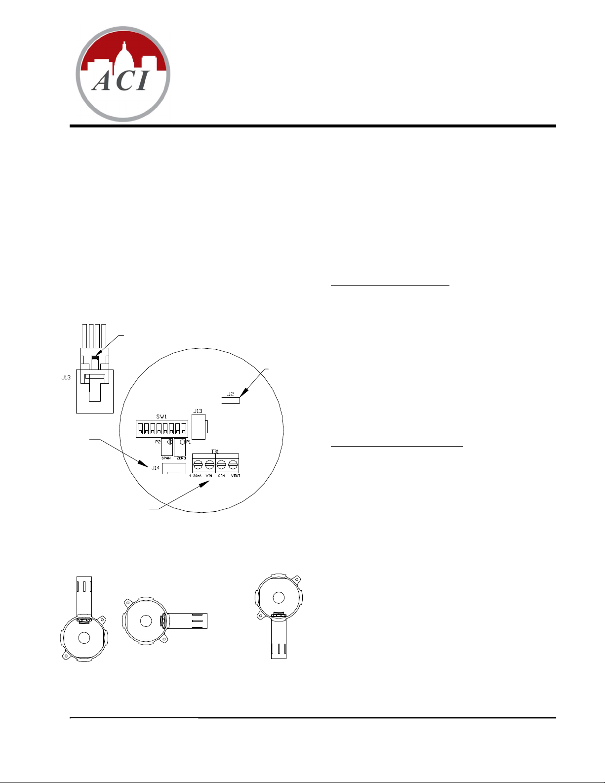
Factory Use Only
Wire Connections
Incorrect
Installation and Operation Instructions
RH Duct and Outside Series
PLEASE READ INSTRUCTIONS CAREFULLY BEFORE INSTALLATION!
MOUNTING INSTRUCTIONS
IMPORTANT: RH Remote Probes and some
Outside units include a Black Rubber Cap that fits
over the sensor filter. The Cap should be placed on
the sensor filter during wet/wash down processes.
The Cap must be removed for normal operation.
Duct Mounting Configuration
Drill a ¾” diameter hole in the duct where the
transmitter is to be mounted. Insert the stainless-steel
probe into the hole until the foam is in direct contact
Push tab in and pull up on the sensor
cable to remove from J13 connector
ON
1342765 8
Figure #1
Figure #2
Factory Use Only
Correct
with the duct. Attach the transmitter to the duct using
the supplied #8 X ¾” self-tapping screws.
Remove the cover and install your conduit connector or
watertight fitting. The outer knockout ring should not be
removed when using a ½” NPT conduit fitting.
After wiring the unit, place the cover back on and gently
turn until it is tight.
Outdoor Mounting Configuration
The transmitter should be mounted under an eave,
shield, or in an area out of the elements or direct
sunlight. The aluminum tube should point down when
mounting the outside transmitter. Refer to Figure #2 for
the proper mounting position.
Place the unit where it is to be mounted with the cover
facing out. Attach the unit with the supplied #8 X ¾”
self-tapping screws.
Remove the cover and install the PG11 watertight fitting
supplied with the unit. The outer knockout ring should
not be removed when using a ½” NPT conduit fitting.
After wiring the unit, place the cover back on and gently
turn until it is tight.
Page 1 of 4 I0000546
Version : 5.0
Page 2
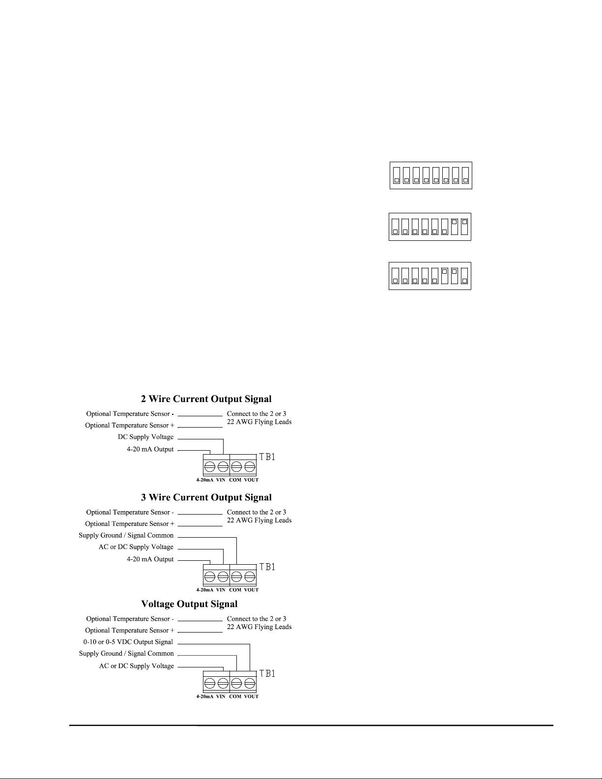
WIRING INSTRUCTIONS
16 to 22 AWG shielded cable is recommended for all
RH Transmitters. Twisted pair may be used for 2-wire
current output transmitters. If using 24 VAC power,
two separate wires must be pulled for the transmitter to
work properly; one 16 to 22 AWG shielded cable for the
supply voltage, and a second 16 to 22 AWG shielded
cable for the selected output(s). Signal wiring must be
run separate from high voltage wires (120-Volt). The
connections to the optional temperature sensor should
be made with wire nuts or crimp style connectors. Refer
to Figure #3 for wiring diagram.
Caution:
It is recommended that you use an isolated
UL-listed Class 2 transformer when
powering the unit with 24 VAC. Failure to
wire the devices with the correct polarity
when sharing transformers may result in
damage to any device powered by the
shared transformer.
Remove power before wiring. Never connect
or disconnect wiring with power applied.
When using shielded cable, ground the
shield only at the controller end. Grounding
both ends can cause a ground loop.
Figure #3
Version : 5.0
Page 2 of 4 I0000546
OUTPUT SELECTIONS
Switches 6, 7, and 8 are used to set the RH output
signal. Refer to Figure #4 for switch settings.
Output Selection Switches (SW1)
4-20 mA Output
ON
ON
2 3
1
OFF
ON
OFF
ON
ON
4 8
5 6 7
0-10 VDC Output
2
3
4
6 81
5ON7
0-5 VDC Output
OFF
1 4 5 6
2 3
7 8
Figure #4
REVERSE ACTING OUTPUT
The output can be changed to reverse acting mode. The
output range stays the same but the corresponding RH
value is opposite.
Example: Direct Acting (DA)
0-10V output mode,
0V = 0% RH and 10V = 100% RH
Reverse Acting (RA)
0-10V output mode,
0V = 100% and 10V = 0%
To change the transmitter to reverse acting or back to
direct acting, set switch 4 ON to put the unit in setup
mode. After switch 4 is on, switch 2 will put the unit in
direct/reverse acting mode. When switch 2 is set to ON,
the output can be used to show if the unit is in direct or
reverse acting mode. For direct acting, the output will
be 1V for 0-5V, 2V for 0-10V, and 7.2mA for 4-20mA.
For reverse acting the output will be 4V for 0-5V, 8V
for 0-10V, and 16.8mA for 4-20mA.
With switches 2 and 4 ON, each time switch 5 is set to
ON the output will change to reverse acting or direct
acting.
To reset the unit to the default setting, toggle both
switches 5 and 6 ON then OFF while both switches 2
and 4 are ON.
When all calibration is completed, remember to place
the switches back into the positions that correspond to
the output needed as shown in Figure #4.
Page 3

RH CALIBRATION INSTRUCTIONS
Note: This is only a single point calibration. All
transmitters are factory calibrated to meet/exceed
published specifications. Field adjustment should not
be necessary.
The dipswitch allows the user to calibrate the sensor
through the software. Setting switch 4 ON will put the
transmitter into setup mode allowing the increment and
decrement to work. Once in setup mode, the output will
change to 50% (2.5V for 0-5V, 5V for 0-10V, 12mA for
4-20mA). Each increment or decrement step will cause
the output to change by 0.1V for 0-5V, 0.2V for 0-10V,
and 0.32mA for 4-20mA in setup mode. This can be
used to show the user how far offset the transmitter is.
To see the starting point again set switch 1 ON. This
will show the 50% output again. When the unit is out of
setup mode the output will go back to RH output.
Increment RH Output
This will shift the RH output linearly up in 0.5% steps.
Switch 4 must be set to ON first. After switch 4 is on,
each time switch 5 is set ON the RH output will
increase by 0.5%. The increase goes into effect each
time switch 5 is set to ON.
Decrement RH Output
This will shift the RH output linearly down in 0.5%
steps. Switch 4 must be set to ON first. After switch 4 is
on, each time switch 6 is set ON the RH output will
decrease by 0.5%. The decrease goes into effect each
time switch 6 is set to ON.
Reset RH Output
This will reset the RH output back to the original
calibration. Switch 4 must be set to ON first. After
switch 4 is on, toggle switches 5 and 6 ON then OFF.
After 5 and 6 are OFF slide switch 4 OFF.
When all calibration is completed, remember to place
the switches back into the positions that correspond to
the output needed as shown in Figure #4.
Note: Potentiometers P1 (Zero) and P2 (Span) in
Figure #1 are not used for RH sensor calibration.
They are used for factory use only
TEST INSTRUCTIONS
Test mode will make the transmitter output a fixed 0%,
50%, or 100% value. The sensor will not affect the
transmitter output. This is used for troubleshooting or
testing only.
Switches 1, 2, and 3 are used for test mode. The output
will be a fixed 0%, 50%, or 100% signal that
corresponds to the output selected with switches 6, 7,
and 8. Refer to Figure #5 for switch settings.
Test Selection Switches (SW1)
0% RH Output
ON
ON
2 3
2
3
4 8
5 6 7
6 81
4
5ON7
OFF
ON
1
50% RH Output
ON
OFF
100% RH Output
ON
2 3
OFF
1 4 5 6
7 8
Figure #5
Page 3 of 4 I0000546
Version : 5.0
Page 4

± 1% o ve r 2 0% sp an (betwe en 20 to 90 % )
RH CONVERSION FORMULAS
To convert output signal to percent RH:
4-20 mA
((mA signal) -4) / 0.16 = percent RH
Example: 12mA output signal
(12-4) / 0.16 = 50% RH
0-5 VDC
(VDC signal) / 0.05 = percent RH
Example: 1.25vdc output signal
1.25 / 0.05 = 25% RH
0-10 VDC
(VDC signal) / 0.10 = percent RH
Example: 7.50vdc output signal
7.50 / 0.10 = 75% RH
PRODUCT SPECIFICATIONS
Supp ly V olta ge
Supp ly C urrent
RH O utpu t
4-20 mA Ou tp ut: 2 5 0 Oh m L oa d 15 - 40 VD C /
18 - 28 V AC
4-20 mA Ou tp ut: 5 0 0 Oh m L oa d 18 - 40 VD C /
18 - 28 V AC (500 O h m Lo ad M ax)
0-5 V D C O ut pu t: 12 - 4 0 VDC / 18 - 28 VA C
(4K L oa d Min im um)
0-10 V DC Ou tp u t: 18 - 40 VDC / 1 8 - 28 V AC
(4K L oa d Min im um)
Vo lta ge O ut pu t: 8mA M ax
Cu rrent O utput : 2 4mA M ax
2-Wire, 4 - 20 m A
3-Wire, 0 - 5V D C, 0 - 10 V D C, or 4 -2 0m A
TROUBLESHOOTING
Problem:
No Reading
Check that you have the correct
supply voltage at the power
terminal blocks.
Check that wiring configurations
and all DIP switch settings are as in
Figures #3 and #4.
Verify that the terminal screws are
all connected tightly and that all of
the wires are firmly in place.
Erratic Readings
Verify that all of the wires are
terminated properly.
Make sure that there is no
condensation on the board.
Check that the input power is clean.
In areas of high RF interference or
noise, shielded cable may be
necessary to stabilize signal.
Inaccurate Readings
If you suspect that the transmitter is
not reading within the specified
tolerance, please contact the factory
RH M easu rem en t Ra nge
RH A ccur ac y @ 7 7oF (25oC)
Re pe atab il ity
Op eratin g H um id it y Enviro nme nt
Op eratin g Tem p. E nvir onm en t
Sto rag e Tem p. Ran ge
for further assistance.
0 t o 10 0% RH
± 2% , 3% , or 5 % from 10 to 95%
0.5 % R H
0 t o 10 0% RH
-40 t o 14 0°F (-40 to 60°C)
-40 t o 16 0°F (-40 to 71°C)
Page 4 of 4 I0000546
Version : 5.0
 Loading...