

Page 1

QIRF
REFRIGERANT GAS
TRANSMITTER/SENSOR
INSTALLATION
OPERATION AND MAINTENANCE
MANUAL
Page 2

QIRF Operation And Maintenance Manual
Table Of Contents
READ BEFORE OPERATING ...................................................................................................................3
1. GENERAL INFORMATION .............................................................................................................3
1.1
P
RINCIPLE OF OPERATION
1.2
K
EY FEATURES
1.3
A
PPLICATIONS
1.4
S
PECIFICATIONS
2. INSTALLATION .................................................................................................................................7
2.1
S
ENSOR LOCATION
2.2
P
HYSICAL DIMENSIONS
2.3
G
AS SAMPLING
2.4
M
OUNTING AND SYSTEM WIRING
2.4.1 Terminals......................................................................................................................................9
2.4.2 Power Supply................................................................................................................................9
2.4.3 Wire and Cable...........................................................................................................................10
2.4.4 Digital Connection .....................................................................................................................10
2.4.5 RS-485 Terminator .....................................................................................................................10
2.4.6 RS-485 Driver Replacement .......................................................................................................11
2.4.7 4-20mA or 2-10VDC Analog Output..........................................................................................11
2.4.8 Relays Output .............................................................................................................................12
..................................................................................................................................4
....................................................................................................................................4
.................................................................................................................................5
..................................................................................................................................8
..................................................................................................................3
.............................................................................................................................7
......................................................................................................................7
......................................................................................................8
3. FUNCTION AND CONFIGURATION ...........................................................................................13
3.1
QIRF W
3.2
S
3.3
K
3.4
S
3.4.1 RS485-TX/RX:..........................................................................................................................15
3.4.2 Relay1-3 LED: ..........................................................................................................................15
3.5
L
3.6
H
3.7
QIRF M
3.8
M
3.8.1 System Settings ...........................................................................................................................18
3.9
M
3.9.1 Equipment Required ...................................................................................................................20
3.9.2 Zeroing Calibration Procedure..................................................................................................20
3.10 M
3.10.1
3.11 M
3.12 M
3.13 M
3.13.1
3.13.2
3.14 M
3.15 M
3.16 M
3.17 M
ORKING MODE
YSTEM INITIALIZATION
EYPAD
...........................................................................................................................................13
TATUS
LED....................................................................................................................................15
ATCHED RELAY RESET
USH BUZZER AND HORN
AIN MENU TREE
ENU
“1_S
YSTEM SETTING
ENU
“2_Z
EROING CALIBRATION
ENU
“3_S
PAN CALIBRATION
Span Calibration Procedure..................................................................................................22
ENU
“4_O
UTPUT TESTING
ENU
“5_S
ITE SERVICE
ENU
“6_R
ELAY DATABASE
Relay Configurations .............................................................................................................24
Relay Database Flow Chart ..................................................................................................26
ENU
ENU
ENU
ENU
“7_A-O
“8_B
“9_O
“10_S
UT DATABASE
UZZER DATABASE
UTPUT DISABLE
IMU DISABLE
....................................................................................................................13
...................................................................................................................13
...................................................................................................................15
................................................................................................................15
.................................................................................................................15
” ...........................................................................................................17
”..................................................................................................20
” .......................................................................................................22
”...........................................................................................................23
".................................................................................................................23
” .........................................................................................................24
”.........................................................................................................27
” .......................................................................................................28
”...........................................................................................................28
” .............................................................................................................28
4. MODBUS PROTOCOL SUPPORTED BY QIRF..........................................................................28
5. MAINTENANCE ...............................................................................................................................29
QIRF Operation Manual May. 01, 2012
85050-301-000 Rev C
1
Page 3

5.1
5.2
DVM C
4MA
AND 20M
QIRF Operation And Maintenance Manual
ONNECTION FOR
A O
UTPUT CALIBRATION
4-20MA
MEASUREMENT
..........................................................................................29
...........................................................................29
6. TROUBLESHOOTING ....................................................................................................................30
QIRF Operation Manual May. 01, 2012
85050-301-000 Rev C
2
Page 4
QIRF Operation And Maintenance Manual
READ BEFORE OPERATING
All individuals who have or will have the responsibility of using, maintaining, or
servicing this product must carefully read this manual. The product will perform as
designed only if it is used, maintained, and serviced in accordance with the
manufacturer’s instructions.
1. General Information
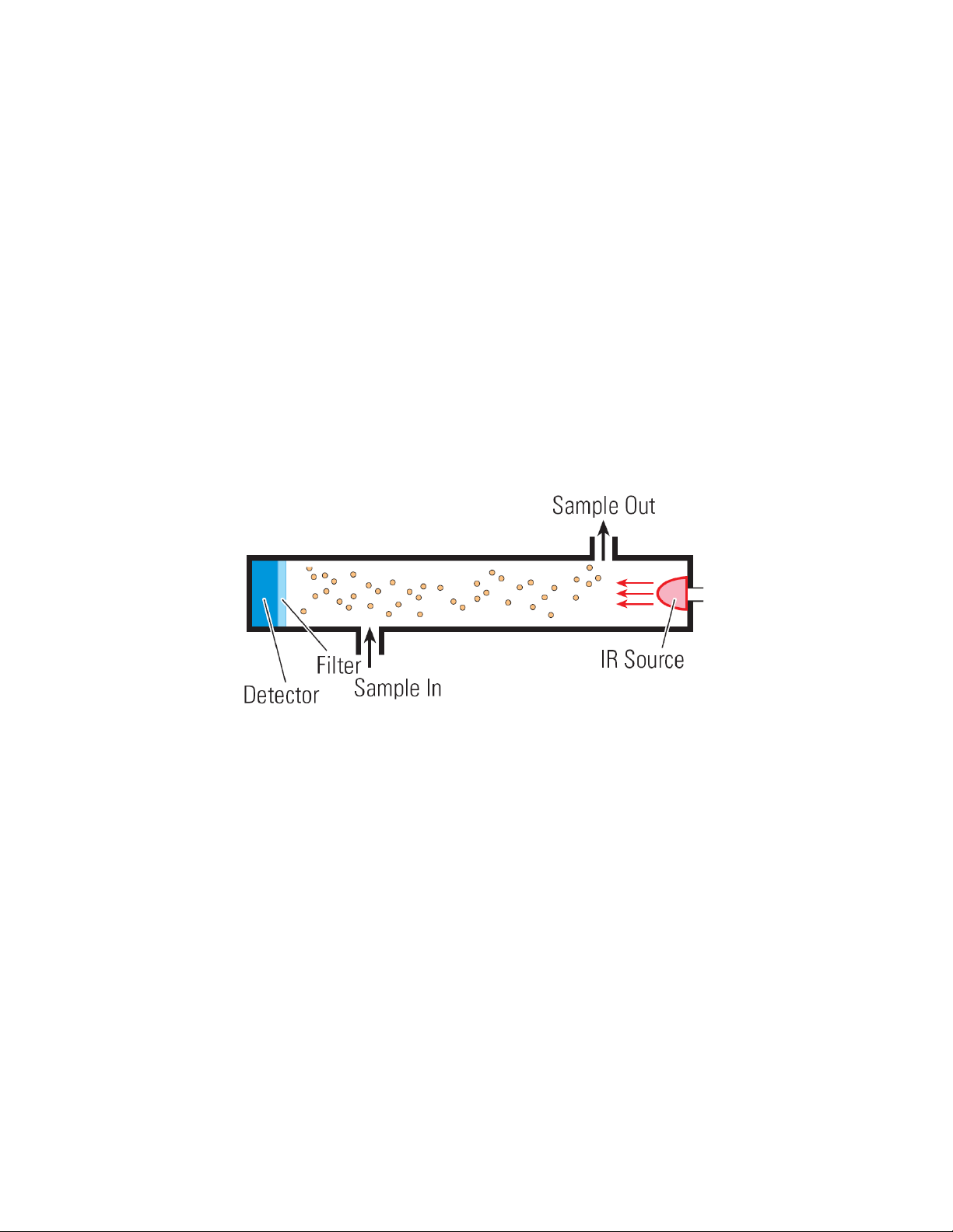
1.1 Principle of Operation
The QIRF Smart Sensor is a microprocessor controlled Refrigerant gas Sensor or
Transmitter using infrared sensing technology. The concentration of Refrigerant is
measured by determining the amount of absorption of light in a specific frequency band.
As most gases have their characteristic spectra in the infrared. Those spectra derive from
the molecule's composition in such a way that no two molecular gases have the same IR
spectrum. IR spectra are the fingerprints of gases, and thus allow gases to be uniquely
identified.
By transmitting a beam of IR radiation through the air, or through any particular gas
volume, and recording how much is transmitted at selected spectral lines, one may decide
which gases are present and how much of each. This is a standard and well-proven
principle, routinely used in laboratory analyses of chemical species, and is also the basis
on which our sensors are made.
An IR detector is essentially a temperature sensor and is, therefore, potentially very
sensitive to changes in the ambient temperature. However, our QIRF smart sensor
modules do it better, faster, and more precisely. The QIRF smart sensors are entirely
electronic with no moving parts, and are built around our unique QT Gas Sample Cell
with constant temperature control integrated with IR Source and IR Detector together.
This makes our IR smart sensors work from -45°C to 65°C without being susceptible to
ambient temperature fluctuations.
QIRF Operation Manual May. 01, 2012
85050-301-000 Rev C
3
Page 5

QIRF Operation And Maintenance Manual
Comparing with conventional gas detector, gases to be detected are often corrosive and
reactive. With most sensor types, the sensor itself is directly exposed to the gas, often
causing the sensor to drift or die prematurely. The main advantage of IR sensor or
transmitter is that the detector does not directly interact with the gas (or gases) to be
detected. In the QIRF Smart Sensor, the major functional components are protected with
optical parts. In other words, gas molecules interact only with a light beam. The IR
Source and IR Detector can be treated, making them resistant to corrosion, and are
designed such that they are easily removable for maintenance or replacement.
1.2 Key Features
• Infrared Sensing Technology
• Constant Temperature QT Gas Sampling Cell
• Standard RS-485 Output with OptoMux protocol and ModBus protocol
• Standard 4-20mA or 2-10VDC Analog Output
• Diffusion Sampling module or Pump-thru module
• No moving parts in diffusion or pump-thru model
• Water and corrosion resistant PVC enclosure NEMA 4, 4X
• Addressable from 0 to 31
• 4 magnetic sensors as keypad input
• 3 programmable Relays and 3 programmable Buzzers
• 2 x 8 character LCD display c/w backlight
• Operation at 18-30VDC or 15–24VAC
• 3 Relay Status LED, TX Status LED and RX Status LED
• CSA/UL approval (pending)
1.3 Applications
The QIRF is designed to monitor for the loss of refrigerant gas in a variety of
applications:
• Mechanical equipment rooms
• Propellant filling operations
• Solvent cleaning stations
• Cold storage and transport facilities
• Meat packing plants
• Supermarkets and refrigerant storage locations
• Other specialty applications using halocarbons
QIRF Operation Manual May. 01, 2012
85050-301-000 Rev C
4
Page 6

1.4 Specifications
Input Power:
Fuse:
Sensor:
Gas Detected:
Range:
Accuracy:
Repeatability:
Sampling:
Panel Indicators:
Display:
Keypad:
Relays:
Buzzer:
QIRF Operation And Maintenance Manual
24VDC nominal, range 18 to 30VDC, 1.0A DC Total Max.
24VAC nominal, range 15 to 24VAC, 1.0A AC Total Max.
F1 on Display Board: Polyswitch 1.6A
F2 on Display Board: Polyswitch 50mA
Polyswitch device resets after the fault is cleared and power
to the circuit is removed
Infrared Refrigerant
User selectable: R11, R12, R22, R114, R123, R134A,
R402A, R404A, R407C, R408A, R409A, R410A, R422A,
R438A, R507A
Available on special order: R13, R14, R21, R23, R31, R32,
R41, R113, R115, R116, R125, R143a, R152, R161 …
0 to 100ppm for R123; 0 to 1000ppm for others
±3% of reading
±1% of full scale
Diffusion or Pump-through
5 Status LED’s
• RS-485 TX Status (Green)
• RS-485 RX Status (Green)
• Relay1 Status (Red)
• Relay2 Status (Red)
• Relay2 Status (Red)
2 x 8 character display c/w backlight
4 magnetic sensors with Magnet tool
3 Relays SPDT, Dry contacts
• 1.0A maximum at 30 VDC (resistive load)
• 0.3A maximum at 125VAC (resistive load)
80 db at 10 cm, 2700 Hz
Buzzer 1: Double-tap Intermittent
Buzzer 2: Intermittent 50% duty cycle
Buzzer 3: Continuous
QIRF Operation Manual May. 01, 2012
85050-301-000 Rev C
5
Page 7

Output Signal:
Enclosure Rating:
Operating Temperature:
Ambient Humidity:
Storage Temperature:
Size:
Weight:
QIRF Operation And Maintenance Manual
RS-485 with OptoMux protocol
• Available Controller: M-Controller
Q4 Controller
RS-485 with ModBus protocol
4-20mA or 2-10VDC Analog Signal
IP 66 & NEMA 4, 4X, 12 & 13
Cover Screws should be torqued to 2.5lbs-in (30cN-m)
-45°C to 65°C
5% to 95% RH (non-condensing)
-45°C to 70°C
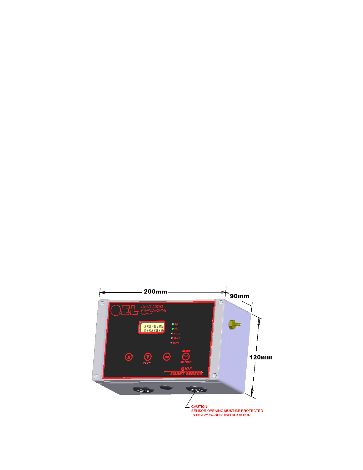
200mm X 120mm X 90mm
Less than 1.5lbs (0.680 kg)
QIRF Operation Manual May. 01, 2012
85050-301-000 Rev C
6
Page 8
QIRF Operation And Maintenance Manual
2. Installation
2.1 Sensor Location
Several factors should be considered when selecting locations to install sensors. The
following general suggestions should be considered to assure the detection of the target
gas. Select the most suitable location for each sensor.
1. Air Currents: If there are fans, winds, or others sources of air movement, gases may
tend to rise or collect in certain areas of a facility. The local air currents should be
assessed to aid in selecting the sensor location. In outdoor situations considerations such
as prevailing winds should be accounted for. Air convection can often be more important
in determining gas concentrated areas than factors of Vapor Density.
2. Vapor Density: R11, R22, R123 and R134A are heavier than air. Detecting location
should be 9 - 18 inch (0.23m to 0.46m) above the floor.
3. Gas Emission Sources: As a rule, at least one sensor should be located in close
proximity to each point where a leak is likely to occur. This is particularly important
when a liquid having a low volatility is monitored.
4. Environmental Factors: Designed to rugged outdoor use consider the following in
selecting locations. Install sensors where they will be protected from wind, dust, snow,
water, vibration and shock.
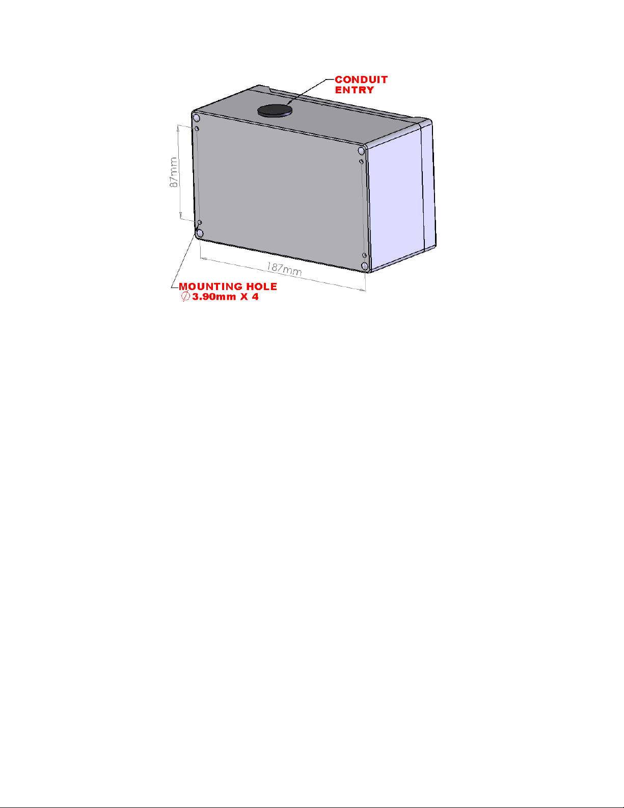
2.2 Physical Dimensions
QIRF Operation Manual May. 01, 2012
85050-301-000 Rev C
7
Page 9
QIRF Operation And Maintenance Manual
2.3 Gas Sampling
In Diffusion version QIRF, the gas sampling system is composed of a diffusion type gas
sample chamber and two vent holes on the enclosure bottom. The gas flows in and out
through the two vent plugs on the bottom of the QIRF enclosure. See above picture.
In Pump-thru version QIRF, the sampling gas is pumped through the fitting on the bottom
of the QIRF enclosure, and passed through the gas chamber, then exhausted out though
the fitting on the right side of the enclosure. Pump-thru version QIRF doesn’t have
pump inside. For gas sampling and conditioning unit, QEL provides SCS-1 (One channel
sampling and conditioning system).
2.4 Mounting and System Wiring
NOTE: The Diffusion version QIRF should be mounted 1 foot (30cm) from the
floor.
QIRF Operation Manual May. 01, 2012
85050-301-000 Rev C
8
Page 10
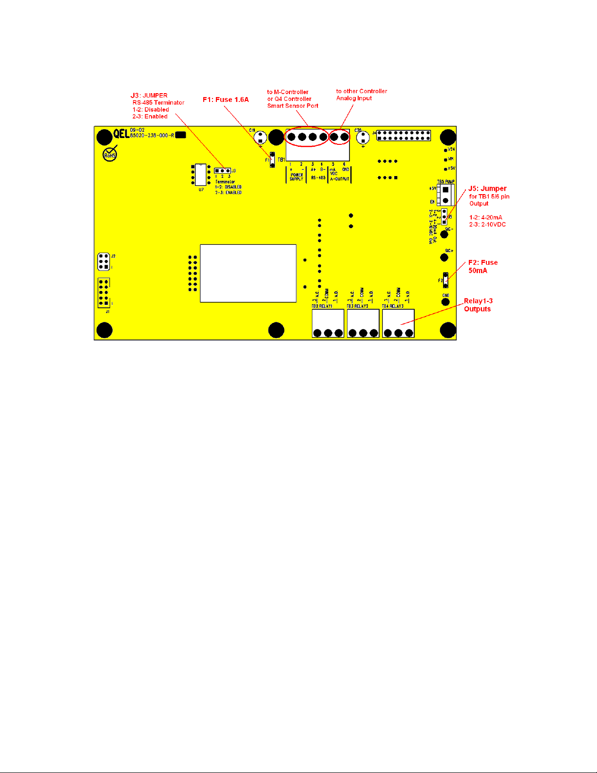
2.4.1 Terminals
QIRF Operation And Maintenance Manual
Display Board Terminals
2.4.2 Power Supply
NOTICE: Installing or using this equipment in a manner not specified by the
manufacturer could cause electric shock, bodily injury, or risk of fire.
Power Supply:
Voltage: 15-24VAC 50/60Hz 1.0A AC Total max.
18-30VDC 1.0A DC Total max.
Note: AC Power Supply must be non-grounded (floating).
Note: No external over-current protection is required. Over-current protection is
provided by means of fuses F1.
Fuse F1: PolySwitch 1.6A
QIRF Operation Manual May. 01, 2012
85050-301-000 Rev C
9
Page 11

QIRF Operation And Maintenance Manual
2.4.3 Wire and Cable
The terminal block plug TB1 accepts 12 AWG to 24 AWG wire, Use 16 AWG or 18
AWG wire for Power Supply in long wiring runs, which can be up to 1km (1,000 meters)
long.
We recommend using BELDEN 9841 for communications. This wire has 120 ohm input
impendence, which will eliminate RS-485 communication problems.
2.4.4 Digital Connection
2.4.5 RS-485 Terminator
The terminator on each end of the RS485 loop is designed to match the electrical
impedance characteristic of the twisted pair loop, and will prevent signal echoes from
corrupting the data on the line. The terminator should be enabled on BOTH ends of the
RS485 loop. Short and medium length modbus/485 loops can operate without the
terminating resistor. Longer runs may require the terminating resistors. But adding
terminator dramatically increases power consumption.
Factory default setting is disabled terminator.
The QIRF smart sensor supplies this resistor on the display board, and it is chosen using a
jumper at J3.
• J3 1-2: Terminator Disabled / OFF (default)
• J3 2-3: Terminator Enabled / ON
QIRF Operation Manual May. 01, 2012
85050-301-000 Rev C
10
Page 12

QIRF Operation And Maintenance Manual
2.4.6 RS-485 Driver Replacement
RS-485 lines in heavy industrial environments are sometimes subjected to magnetic
disturbances causing sufficient inducted power surges to damage the driver integrated
circuit (IC). This IC U7 has a socket on the circuit card for ease of replacement in the
field.
2.4.7 4-20mA or 2-10VDC Analog Output
QIRF can provide one channel 4-20 milliamp analog outputs or 2-10VDC analog output.
The maximum output impedance is 600 ohms for 4-20mA output. The maximum output
current is 10 mA for 2-10VDC output.
Test point SIG+ and SIG- are used to measure the current online when the QIRF is
working in the field.
The module can also be used to output 2-10VDC if the Jump J5 2-3 is connected. The
default setting: J5 1-2 is connected that mean the output is 4-20mA analog output.
The analog output may be defined in complex ways allowing assignment of different
values to both 4 milliamps and 20 milliamps. You may even assign a gas concentration to
4 mA, which is higher than the concentration assigned to 20 milliamps. The QIRF will
draw a straight line between.
If there is any fault found in QIRF, it will output 2.5mA to indicate the fault.
QIRF Operation Manual May. 01, 2012
85050-301-000 Rev C
11
Page 13

QIRF Operation And Maintenance Manual
2.4.8 Relays Output
QIRF is equipped with three programmable Single-Pole Double-Throw (SPDT) Relays
on board, which is able to make it work alone to control other equipment, such as fans,
lights, horns, or visual alarm indicators in different applications.
Three terminal blocks TB2, TB3 and TB4 are located on the Display Board. Each relay
can be programmed individually.
Switching capability of each relay is:
• 1.0 A maximum resistive load at 30 VDC
• 0.3A maximum resistive load at 125VAC
QIRF Operation Manual May. 01, 2012
85050-301-000 Rev C
12
Page 14

QIRF Operation And Maintenance Manual
3. Function and Configuration
3.1 QIRF Working Mode
QIRF has four kinds of working mode:
• Warm-up Mode: to heat up Optical Block and initialize components.
• Monitoring Mode: to measure the gas concentration and output signals.
• Zeroing Calibration Mode: QIRF is performing Zeroing Calibration.
• Span Calibration Mode: QIRF is performing Span Calibration.
3.2 System Initialization
When the QIRF smart sensor is turned on, it initializes hardware and software. As the
transmitter is warming up, the optical block is heated to a constant temperature, the LCD
will display the transmitter is in warming-up procedure.
In warming-up procedure, the reading of the transmitter will always be zero and the
analog output will always be 4mA. M-Controller and Q4 Controller will display
“Warming up” in their LCD display panel. The time for stabilizing the optical block
temperature depends on the ambient temperature and input power voltage. The lower the
ambient temperature and input voltage are, the longer it takes. Normally, at 25°C and 24V
input voltage, it takes 15 minutes. The default warming-up timer is 24 hours, the
warming-up procedure can be aborted by pressing key [ESC] for 3 seconds. The
warming-up timer can be set again in [MENU]=>[System Setting]=>[Zero/Cal Timer].
If the warming-up procedure is not aborted, when timeouts, the transmitter automatically
starts zeroing calibration, then enters into monitoring mode. If there is an error, the LCD
will display the error and the TB1 pin 5/6 will output 2.5mA if the 4-20mA analog
outputs is enabled or 1.25VDC if the 2-10VDC analog outputs is enabled. An error
message will display on the M-Controller or Q4 Controller panel.
Note: After warming-up procedure, an error [PH-DIRTY] might appear which is
caused by low ambient temperature or low input power voltage. The error will
disappear when unit is fully stabilized. If not, see section 6. Troubleshooting.
Note: No adjustments or calibration should be performed within 24 hours.
3.3 Keypad
QIRF has four keys on the front panel. To access the keypad, the magnet tool in the
product-shipping package is needed.
• Key [Up]: Scroll and Hold
• Key [Down]: View current input or output details
QIRF Operation Manual May. 01, 2012
85050-301-000 Rev C
13
Page 15

QIRF Operation And Maintenance Manual
• Key [ESC]: Return to previous menu or Hush Buzzer or Reset Latched Relay
• Key [YES]: Enter Menu or Confirm answers
start
Is UP key?
NO
Is DOWN key?
NO
Is EXIT/CLEAR key?
NO
YES
YES
YES
Scroll and Hold
Display
Display Detail
about the output
Hold 3 seconds?
NO
Character "*" indicates the screen is in HOLDMode.
The screen will be held for 120 seconds
Press the DOWN key will browse the detail of the
current output which is able to be selected by UP
key.
Reset all Relays in
YES
Latched Satus
Hush all Buzzers in
Alarm Status
Is ENTER key?
NO
YES
Hold 3 seconds?
YES
PASSWORD
> NNNN
NO
Passoword is Correct?
NO
YES
ENTER
MENU MODE
B
QIRF Running Mode Key Functions Flow Chart
QIRF Operation Manual May. 01, 2012
85050-301-000 Rev C
14
Page 16

QIRF Operation And Maintenance Manual
3.4 Status LED
3.4.1 RS485-TX/RX:
When the QIRF is connected to a Controller System through RS-485, the traffic of the
communication can be monitored visually through the two RS-485 indicators. One is RX
LED, which indicates the data stream received in the Controller. The other is TX LED,
which indicates the data stream out of the QIRF.
Note: If the TX LED or the RX LED is always ON, that means the communication
has a problem. See Troubleshooting for RS-485.
3.4.2 Relay1-3 LED:
Indicate the status of each relay. When the relay is actuated/closed, the Relay LED is ON.
When the relay is de-actuated/open, the relay LED is OFF.
Note: If you set the relay to be Normally Energized Relay (Fail Safe), the relay LED
will turn ON at non-alarm state and turn OFF at alarm state, because the LED
reflects the relay coil status.
3.5 Latched Relay Reset
To acknowledge a latched condition, press Key [ESC] for 3 seconds. All latched relays
for which the alarm condition has been removed will reset. If the alarm condition (e.g.
high gas concentration) is still present the relay(s) will not reset.
3.6 Hush Buzzer and Horn
Press Key [ESC] to silence the buzzer and horn. Press the Key [ESC] again to remove the
hush function.
3.7 QIRF Main Menu Tree
Menu is password protected. Press and hold Key [YES] for 3 seconds, you will be
prompted to input a four-digit password. Once the password is accepted, you are allowed
into the main menu tree. Press button [Up] or [Down] to scroll through the main branch
headings, press button [YES] to enter the function, press button [ESC] to exit to up level
menu.
Factory default password is 4321.
Note: While in the Menu Tree, all normal monitoring operations stop. The alarm
status does not change.
QIRF Operation Manual May. 01, 2012
85050-301-000 Rev C
15
Page 17

QIRF Operation And Maintenance Manual
B
ESC
ESC
ESC
ESC
ESC
ESC
ESC
ESC
ESC
ESC
MENU MODE
MENU MODE
MENU MODEMENU MODE
C C1
1_ SYSTEM
SETTING
Up
2_ ZERO
CAL
Up
3_ SPAN
CAL
Up
4_ OUTPUT
TESTING
Up
5_ SITE
SERVICE
Up
6_ RELAY
DATABASE
Up
7_ A-OUT
DATABASE
Up
8_ BUZZER
DATABASE
Up
9_ OUTPUT
DISABLE
Up
10_ SIMU
DISABLE
Up
Down
Down
Down
Down
Down
Down
Down
Down
Down
Down
YES
YES
YES
YES
YES
YES
YES
YES
YES
YES
ESC
ESC
ESC
SYSTEM SETTING
ZEROING?
SUBDIVISION
YES
NN PPM
SPAN CAL?
NN PPM
ESC
ESC
ESC
ESC
ESC
ESC
ESC
OUTPUT TESTING
SUBDIVISION
SITE SERVICE
SUBDIVISION
RELAY DATABASE
SUBDIVISION
A-OUT DATABASE
SUBDIVISION
BUZZER DATABASE
SUBDIVISION
ALL OUTPUTS CAN BE
DISABLED AT CALIBRATION
SIMULATE
ENABLE
YES
YES
SEE SYSTEM SETTING Page
S3 R134a
ZERO...
S3 R134a
CAL...
SEE TESTING Page
SEE RelayDataBase Page
SEE AOUTDataBase Page
SEE BuzzerDataBase Page
READING
NNN PPM
ACCEPTED
ACCEPTED
ACCEPTED
Down
C
+
QIRF Menu Tree Flow Chart
QIRF Operation Manual May. 01, 2012
85050-301-000 Rev C
16
Page 18

QIRF Operation And Maintenance Manual
3.8 Menu “1_System Setting”
System Setting Subdivision contains general settings for monitor operations,
communications and 4-20mA calibrations.
RETURN
TO UP LEVEL
S S1
PRESS KEY UP AND KEY
ESC
ESC
ESC
ESC
ESC
ESC
ESC
ESC
ADDRESS
001
Up
BAUDRATE
4800 bps
Up
SCROLL
3 SEC
Up
BACKLIGHT
ON
Up
4mA CAL
150
Up
20mA CAL
910
Up
CHANGE
PASSWORD
Up
PROTOCOL
OPTOMUX
Up
Down
Down
Down
Down
Down
Down
Down
Down
YES
YES
YES
YES
YES
YES
YES
ESC
YES
ESC
ESC
ESC
ESC
ESC
ESC
New PSW
> NNNN
ESC
DOWN TO MODIF Y
NEW ADDR
> 0003
New Rate
> 57.6
New Rate
> 4
New Mode
> AUTO
ADJ 4mA
> 183
ADJ 20mA
> 928
YES
New Mode
MODBUS
ESC
YES
YES
YES
YES
YES
YES
YES
IN AGAIN
> NNNN
Is ModBus?
ACCEPTED
ACCEPTED
ACCEPTED
ACCEPTED
ACCEPTED
ACCEPTED
NO
YES
YES
The two func tion
are used to
calibrate An alog
Output 4-20m A.
ACCEPTED
PARITY?
ODD/EVEN/NONE
ACCEPTED
Down
GAS TYPE
ESC
R134a
Up
AUTOZERO
ESC
OFF
Up
ESC
RESTORE
DEFAULTS
Up
SPEC GAS
ESC
DISABLE
Up Down
S
QIRF Operation Manual May. 01, 2012
YES
Down
YES
Down
YES
ESC
Down
YES
S1
ESC
New Mode
> ENABLE
ESC
ESC
RESTORE
ESC
YES/NO?
New Gas?
YES
> R123
New Mode
YES
> ON
YES
YES YES
SPEC GAS
> R427A
FACTORY
DEFAULTS
ACCEPTED
ACCEPTED
SPEC UNIT
> PPM
YES
ACCEPTED
17
85050-301-000 Rev C
Page 19

3.8.1 System Settings
QIRF Operation And Maintenance Manual
Password:
Address:
Baud rate:
Scroll Rate:
Backlight:
4mA Cal
20mA Cal:
Default password is 4321.
M-Controller supports RS-485 addressing from 0 to 31 for digital sensor.
Q4 Controller supports RS-485 addressing from 0 to 3 for digital sensor.
The QIRF smart sensor RS-485 address can be defined from 0 to 255 to be
used in RS-485 OptoMux or ModBus communication. Default address is
3.
Define Baud Rate for RS-485 OptoMux or ModBus Communication.
Default baud rate is 4800 bps.
In normal operation the sensor and relay status information scrolls
automatically. Set the number of seconds for each item to be displayed.
Default value is 3 seconds.
The LCD backlight can be set to Always Off, Always On and Power
Saver. In Power Saving mode, the backlight will turn on for 10 seconds
after any Key has been pressed. Default setting is Always ON mode.
These values are established during factory calibration for 4-20mA analog
output and should not require recalibration in the field. Do not attempt to
modify these settings in the field.
Change
Password:
Protocol:
Changing these values will change the analog output signal scale.
Warning: This procedure is part of factory setup. In most
circumstances it will not be necessary to perform this procedure in the
field. These functions require the use of precision reference
instrumentation.
Change Password allows any combination of up to four digits. Default
password is 4321.
Warning: Be sure that you record the new password in a safe and
secure location!
When QIRF is connected to M-Controller or Q4-Controller, the protocol
should be set to “OptoMux”. Default protocol is OptoMux.
QIRF also supports “ModBus” protocol, responds as a ModBus Slave
using RTU protocol. When it’s set to “ModBus”, the parity bit can be
defined as “EVEN”, “ODD” and “No Parity”.
QIRF Operation Manual May. 01, 2012
85050-301-000 Rev C
18
Page 20

QIRF Operation And Maintenance Manual
Gas Type
AutoZero:
Default Gas Type is R134a.
Note: All units are gas calibrated using 1000ppm R134a in factory.
You can change the Gas Type to other target gas type without using
target gas to calibrate again. Zero Calibration is recommended after
the gas type is changed.
For the gas type that QIRF supports, see 1.4 Specifications
For other gas types, please consult QEL.
Note: When the unit is connected to Q4 Controller, Q4 Controller can poll
out the Gas Type automatically and display the gas type in its LCD
display. When the unit is connected to M-Controller, the M-Controller
will only use the Gas Type and Measurement Unit that are defined for the
channel in M-Controller.
QIRF is two channel detector, it’s designed to work in the situation where
the Auto Zero function is not suitable. So QIRF discards AutoZero setting,
QIRF will never do auto zero in background.
Restore
Default:
Special
Gas:
Zero/Cal
Timer:
NOTE: “AutoZero” works best in situations where the facility is
exposed to non-refrigerant-existing air at least four times in 7 days. In
facilities that are continuously occupied for 24 hours per day, or
where there could be significant sources of non-occupant related
refrigerant gas, the Auto Zero should be turned OFF.
To load defaults to all items. Perform a full factory and gas calibration to
restore the unit to correct operation. After restore default, the unit needs to
be recalibrated with Zeroing Calibration and Span Calibration
When the unit is calibrated to a special gas type that is not listed in above
Gas Type list, you can enable the Special Gas Type and input the special
Gas Type and Measurement Unit, which will override the Gas Type
defined in above Gas Type Menu for QIRF LCD display and Q4
Controller LCD display.
The timer can be set from 1 seconds to 99 hours. When the timer is
timeouts, the units will perform Zeroing Calibration automatically. If the
timer is set, the unit will work in Warming-up Mode, after Zeroing
Calibration, the unit returns to Monitoring Mode.
QIRF Operation Manual May. 01, 2012
85050-301-000 Rev C
19
Page 21

QIRF Operation And Maintenance Manual
3.9 Menu “2_Zeroing Calibration”
Calibration should not vary significantly over a period of years; however, it is best to
perform a verification calibration after installation, and at one-year intervals thereafter.
All units are factory calibrated.
The QIRF uses full scale as its CAL GAS concentration:
Basically, QIRF full scale for all Refrigerant gases is 1000ppm except for R123, which is
100ppm.
Gas Type Full Scale Cal Gas Concentration
R134a 1000ppm 1000ppm
R123 100ppm 100ppm
R22 1000ppm 1000ppm
R11 1000ppm 1000ppm
Others 1000ppm 1000ppm
The QIRF smart sensor is calibrated using a two-point calibration process. First, use a
“Zero Gas”, then use a “CAL Gas” containing a known concentration of a standard
reference gas, to set the second point of reference.
3.9.1 Equipment Required
• A cylinder of Zero Gas: it can be clean room air or Zero Air (20.9% Oxygen in
Nitrogen). DO NOT USE PURE NITROGEN.
• A cylinder of Cal Gas (balanced with air, DO NOT USE BALANCED
WITH NITROGEN)
• Flow Limiting Regulator(s) 0.4 to 0.6 lpm
• Tubing
3.9.2 Zeroing Calibration Procedure
2_ ZERO
CAL
YES
ESC
ZEROING?
NN PPM
YES
S3 R134a
ZERO...
ACCEPTED
Zeroing Calibration Flow Chart
Note: No adjustments or calibration should be performed within 24 hours
stabilization.
Note: Zeroing Calibration must be performed before Span Calibration.
1. Connect tubing to QIRF
QIRF Operation Manual May. 01, 2012
85050-301-000 Rev C
20
Page 22

QIRF Operation And Maintenance Manual
• For Diffusion Version: Connect the zero gas supply tubing to the fitting on the
right side of enclosure
• For Pump-through Version: Connect the zero gas supply tubing to the push-in
fitting on the bottom side of enclosure
2. Turn on the gas flow and press Key [YES] to display current reading
ZEROING?
NN PPM
This screen is displaying the current reading and asking if you want to perform
Zeroing Calibration.
3. Waiting for about 3 minutes or till the reading is stable.
4. Press Key [YES] to perform Zeroing Calibration.
5. During Zeroing Calibration, the LCD will display the digital pot positions and
calibration statuses. It will take 3 to 10 minutes to perform Zeroing Calibration, then
the zero calibration data is saved and LCD displays “Accepted”.
6. If the LCD displays “Cal Error” that means something is wrong in the procedure,
repeat procedure 4 to try again. If the “Cal Error” is still displayed in the end, the unit
needs to be repaired in factory, otherwise, Zeroing Calibration has succeeded, go to
next step.
7. Turn off the gas flow and remove it.
QIRF Operation Manual May. 01, 2012
85050-301-000 Rev C
21
Page 23

QIRF Operation And Maintenance Manual
3.10 Menu “3_Span Calibration”
3_ SPAN
CAL
YES
ESC
SPAN CAL?
NN PPM
Span Calibration Flow Chart
3.10.1 Span Calibration Procedure
1. Connect tubing to QIRF
• For Diffusion Version: Connect the cal gas supply tubing to the fitting on the
right side of enclosure
• For Pump-through Version: Connect the cal gas supply tubing to the push-in
fitting on the bottom side of enclosure
YES
S3 R134a
CAL...
ACCEPTED
2. Turn on the gas flow and press Key [YES] to display current reading
SPAN CAL?
NN PPM
This screen is displaying the current reading and asking if you want to perform
Span Calibration.
3. Waiting for about 3 minutes or till the reading is stable.
4. Press Key [YES] to perform Span Calibration.
5. During Span Calibration, the LCD will display the digital pot positions and
calibration statuses. It will take about 1 minute to perform Span Calibration, then the
span calibration data is saved and LCD displays “Accepted”.
6. If the LCD displays “Cal Error” that means something is wrong in the procedure,
repeat procedure 4 to try again. If the “Cal Error” is still displayed in the end, the unit
needs to be repaired in factory, otherwise, Span Calibration has succeeded, go to next
step.
7. Turn off the gas flow and remove it.
QIRF Operation Manual May. 01, 2012
85050-301-000 Rev C
22
Page 24

QIRF Operation And Maintenance Manual
3.11 Menu “4_Output Testing”
For system installation testing, it is necessary to force relay and buzzer actions. Enter this
branch as shown in the flow diagram.
The Relay Testing feature allows the user to force actuation on each relay. This function
forces an Actuate vs. De-actuate action, not an energized vs. non-energized action.
Therefore the user must be aware of those relays, which have been defined as normally
energized or not normally energized.
RETURN
TO UP LEVEL
F F1
ESC
ESC
ESC
Up
Up
Up
RELAY
TEST
BUZZER
TEST
A-OUT
TEST
Down
Down
Down
YES
YES
YES
ESC
ESC
ESC
ESC
ESC
Down
Down
YES
YES
YES
YES
YES
ESC
ESC
ESC
ESC
ESC
BUZZER
OFF
OUTPUT
20mA
RELAY 1? RELAY
Up
RELAY 2?
Up
RELAY 3?
BUZZER
ON
OUTPUT
4mA
ON
RELAY
ON
RELAY
ON
F F1
Output Testing Flow Chart
3.12 Menu “5_Site Service"
Factory Service Staff access Site Service only. Customer has no need to operate it.
QIRF Operation Manual May. 01, 2012
85050-301-000 Rev C
23
Page 25

QIRF Operation And Maintenance Manual
3.13 Menu “6_Relay Database”
3.13.1 Relay Configurations
Enabled:
Normally
Deenergized:
Latching:
Action On:
Action Off:
Each relay may be individually set to be enabled or disabled. If it’s
disabled, the relay is always de-actuate no matter what’s the current gas
concentration.
Default is Enabled.
Each relay may be individually set to be Normally Energized or Normally
De-energized.
Default is De-energized.
Each relay may be set to latch in Actuate status until acknowledged by a
front-panel action. Hold the button [ESC] for 3 seconds to release latched
relays.
Default is Non-Latching.
If Action On is greater than or equal to Action Off (Window=OFF):
Action On: Set the concentration at or above which the relay will actuate.
Action Off: Set the concentration at or below which the relay will deactuate.
If Action On is less than Action Off (Window=OFF):
Action On: Set the concentration below that the relay will actuate.
Action Off: Set the concentration above that the relay will de-actuate.
Defaults for 1000ppm Detection Range:
• Relay1 Action On / Off: 500 / 480 ppm
• Relay2 Action On / Off: 750 / 720 ppm
• Relay3 Action On / Off: 1000 / 950 ppm
QIRF Operation Manual May. 01, 2012
85050-301-000 Rev C
24
Page 26

QIRF Operation And Maintenance Manual
Defaults for R123 100ppm:
• Relay1 Action On / Off: 50 / 45 ppm
• Relay2 Action On / Off: 75 / 70 ppm
• Relay3 Action On / Off: 100 / 95 ppm
ON Delay:
“Delay on Actuation” or “Delay on Make”. For each relay a separate time
delay may be set from 0 to 990 seconds before an alarm condition will
cause the relay to actuate.
Default is 30 seconds.
OFF Delay:
“Delay on De-Actuation” or “Delay on Break”. For each relay a separate
time delay may be set from 0 to 990 seconds before a return to a nonalarming signal condition will cause the relay to de-actuate.
Default is 30 seconds.
Fault:
Set to ON for actuating the relay if the unit reports any Faults.
Default is ON.
Window: When it’s set to ON, if the concentration is between Action ON and
Action Off, the relay will be de-actuated; if the concentration is out of the
windows (Action ON and Action Off), the relay will be actuated.
Default is OFF.
QIRF Operation Manual May. 01, 2012
85050-301-000 Rev C
25
Page 27

QIRF Operation And Maintenance Manual
3.13.2 Relay Database Flow Chart
CHOOSE A RELAY TO MODIFY
ESC
ESC
ESC
Up
Down
Up
Down
Up
Down
Up
Down
RETURN
TO UP LEVEL
MODIFY
RELAY1?
YES
RELAY1?
ENABLED
YES
1.NORMAL
ENERGIZE
YES
1. WITH
LATCHING
YES
MODIFY
RELAY2
RELAY1?
DISABLED
2.NORMAL
DE-ENERGIZE
2. NONE
LATCHING
YES
Up
Down
MODIFY
RELAY3
FINISHED
ACT-ON #?
> NNNN
YES
ACT-OFF #?
> NNNN
YES
ON-DLY#?
NNNN
YES
OFF-DLY#?
NNNN
YES
FAULT?
ON
YES
WINDOW?
ON
ESC
ESC
ESC
ESC
ESC
ESC
DELAY IS VALID BETWEEN 0 TO 990 SECONDS
Up
Down
Up
Down
FAULT?
OFF
WINDOW?
OFF
ANY FAULT WILL ACTUATE THE RELAY
READING OUT OF WINDOWS WILL ACTUATE THE RELAY
FINISHED!
QIRF Operation Manual May. 01, 2012
26
85050-301-000 Rev C
Page 28

QIRF Operation And Maintenance Manual
3.14 Menu “7_A-Out Database”
The Analog Database setup is almost identical to that of the relays.
QIRF will compare the concentration at 4mA and the concentration at 20mA, you may
assign a larger concentration for 4.0 milliamps than for 20 milliamps; the QIRF will still
stretch a straight line signal between the two points and then convert the current gas
reading to analog output.
Note: The Analog Output can not be disabled.
Note: When the sensor has fault, it will output 2.5mA to indicate fault status.
Conc@4mA:
Conc@20mA:
Input the gas concentration at which the 4mA is output.
Default is 0 ppm.
Input the gas concentration at which the 20mA is output.
Default is 1000 ppm.
RETURN
TO UP LEVEL
ESC
MODIFY
A-OUT?
YES
ESC
CONC @ 4mA
> NNNN
YES
ESC
CONC @ 20mA
> NNNN
YES
FINISHED!
QIRF Operation Manual May. 01, 2012
85050-301-000 Rev C
27
Page 29

QIRF Operation And Maintenance Manual
3.15 Menu “8_Buzzer Database”
The buzzer setup is almost identical to that of the relays, except that there are three butter
options.
• Buzzer 1: Double-tap Intermittent
• Buzzer 2: Intermittent 50% duty cycle
• Buzzer 3: Continuous
Buzzer 3 has highest priority and Buzzer 1 has lowest priority.
The menus are identical to those for the Relay Database. For Relay Database detail and
flow chart, please refer 3.13 Menu “6_Relay Database” on page 24.
3.16 Menu “9_Output Disable”
This function is for calibration, system testing etc. When Output is disabled, the relay,
buzzer and analog output, etc., statuses will freeze in whatever state they are already in.
Default is “Output Enabled” when the unit is powered up.
3.17 Menu “10_Simu Disable”
Simulation Mode is to assist in testing the installation before commissioning. When the
simulation is enabled, the unit will not detect gas concentration, it will display the
simulating value and use it to calculate the statuses of relays and buzzer, as well as 420mA analog output. This feature is available for evaluating the user settings and testing
the installation (e.g.: the travel of the valve, fan speed, relay set points, etc. can be
verified.)
Any concentration between 0ppm and 9999ppm can be simulated.
Default is “Simu Disabled” when the unit is powered up.
4. MODBUS Protocol Supported By QIRF
For ModBus protocol, please contact QEL.
QIRF Operation Manual May. 01, 2012
85050-301-000 Rev C
28
Page 30

QIRF Operation And Maintenance Manual
5. Maintenance
5.1 DVM Connection for 4-20mA measurement
• QIRF is Offline of the 4-20mA loop:
o Switch DVM to measure DC current, plug the probe “-“ into GND and
plug the probe “+” into SIG- on the Display Board.
• QIRF is Online of the 4-20mA loop:
o Switch DVM to measure DC current, plug the probe “-“ into SIG - and
plug the probe “+” into SIG + on the Display Board.
5.2 4mA and 20mA Output Calibration
These values are established during factory 4-20mA output calibrations and should not
require recalibration in the field. Do not attempt to modify these settings in the field.
Changing these values will change the analog output signal scale.
• Entry [Menu]-->[System Setting]
• Choose [4mA CAL]:
1. Press Key [YES] to output 4mA signal
2. Connect DVM to the unit as described above
3. Press Key [Up] and Key [Down] to adjust the current to 4.00mA to 4.05mA
4. Press Key [YES] again, then the settings will be accepted and saved
• Choose [20mA CAL]:
1. Press Key [YES] to output 20mA signal
2. Connect DVM to the unit as described above
3. Press Key [Up] and Key [Down] to adjust the current to 20.00 to 20.05mA
4. Press Key [YES] again, then the settings will be accepted and saved
QIRF Operation Manual May. 01, 2012
85050-301-000 Rev C
29
Page 31

QIRF Operation And Maintenance Manual
6. Troubleshooting
This troubleshooting guide is intended as an aid in identifying the cause of unexpected
behavior and determining whether the behavior is due to normal operation or an internal
or external problem.
SYMPTOMS PROBABLE CAUSE SUGGESTED SOLUTION
RS-485
RX LED or
TX LED constantly ON
In Warm Up Mode too long
Error Report
[PH-DIRTY]
[LP-SHORT] /[LP-OPEN]
[CAL-ERR]
• RS-485 bus connection has
problem
• RS-485 Driver U7 is damaged
• Controller side RS-485 Driver
has problem
• In Warming up process
• Temperature sensor broken
• Heater is broken
• IR Source or Lamp Dirty
• Gas Sample Cell Dirty
• Signal Fault
• Drift too much
• Lamp Short/Open
• Calibrating Error
• Disconnect the Cable to isolate
the problem
• Replace U7 IC on display board
• Replace RS-485 Driver in
Controller
• Wait for the block to warm up
• Check IR Block Assembly
• Check IR Block Assembly
• Return to Factory
• Return to Factory
• Return to Factory
• Re-zeroing calibration
• Check IR Block Assembly
• Recalibration or Adjust POTs or
IR Source LED is constant
ON or OFF, not blinking
Reading abnormally high or
low or jumping around
randomly
• Other Error
• Main Board has problem
•
Heater is short/Open
• Dirty Sensor Block
• Excessive moisture
• Weak IR Source
• Temperature Sensor Loose
Check Gas Flow or Use different
calibration gas or Replace weak
IR Source Assembly or Replace
Broken IR Detector Assembly
• Return to Factory
• Check Firmware and Driver
• Check IR Block Assembly
• Return to Factory
• Add filter to gas inlet
• Replace IR Source Assembly
• Check IR Block Assembly
QIRF Operation Manual May. 01, 2012
85050-301-000 Rev C
30
Page 32

QIRF Operation And Maintenance Manual
WARRANTY STATEMENT
The information contained in this manual is based upon data considered accurate; however, no
warranty is expressed or implied regarding the accuracy of this data. All QEL equipment is
warranted against defects in material and workmanship for a period of two years from date of
shipment with the following exceptions:
Electrochemical Sensors (Toxic) Six Months
Catalytic Sensors (Combustible) One Year
During the warranty period we will repair or replace, at our discretion, any components or
complete units that prove, in our opinion, to be defective. We are not liable for consequential or
incidental damage to auxiliary interfaced equipment.
A returned material authorization number should be obtained from the factory prior to returning
any goods. All return shipments must be shipped freight prepaid and a copy of the maintenance
records should accompany the unit concerned.
Warranty should be considered F.O.B. the factory. Labour and travel time are chargeable for any
field site visits required for warranty work.
LIMITED LIABILITY
All QEL systems shall be installed by a qualified technician/electrician and maintained in strict
accordance with data provided for individual systems in the form of installation/maintenance
manuals. QEL assumes no responsibility for improper installation, maintenance, etc., and
stresses the importance of reading all manuals. QEL shall not be responsible for any liability
arising from auxiliary interfaced equipment nor any damage resulting from the installation or
operation of this equipment.
QEL’s total liability is contained as above with no other liability expressed or implied, as the
purchaser is entirely responsible for installation and maintenance of systems.
This warranty is in lieu of all other warranties, expressed or implied, and no representative or
person is authorized to represent or assume for QEL any liability in connection with the sales of
our products other than that set forth herein.
NOTE: Due to on-going product development, QEL reserves the right to change
specifications without notice and will assume no responsibility for any costs as a
result of modifications.
For further information or assistance, contact:
QIRF Operation Manual May. 01, 2012
85050-301-000 Rev C
31
 Loading...