

Page 1
Automation Components, Inc.
M-CONTROLLERGAS
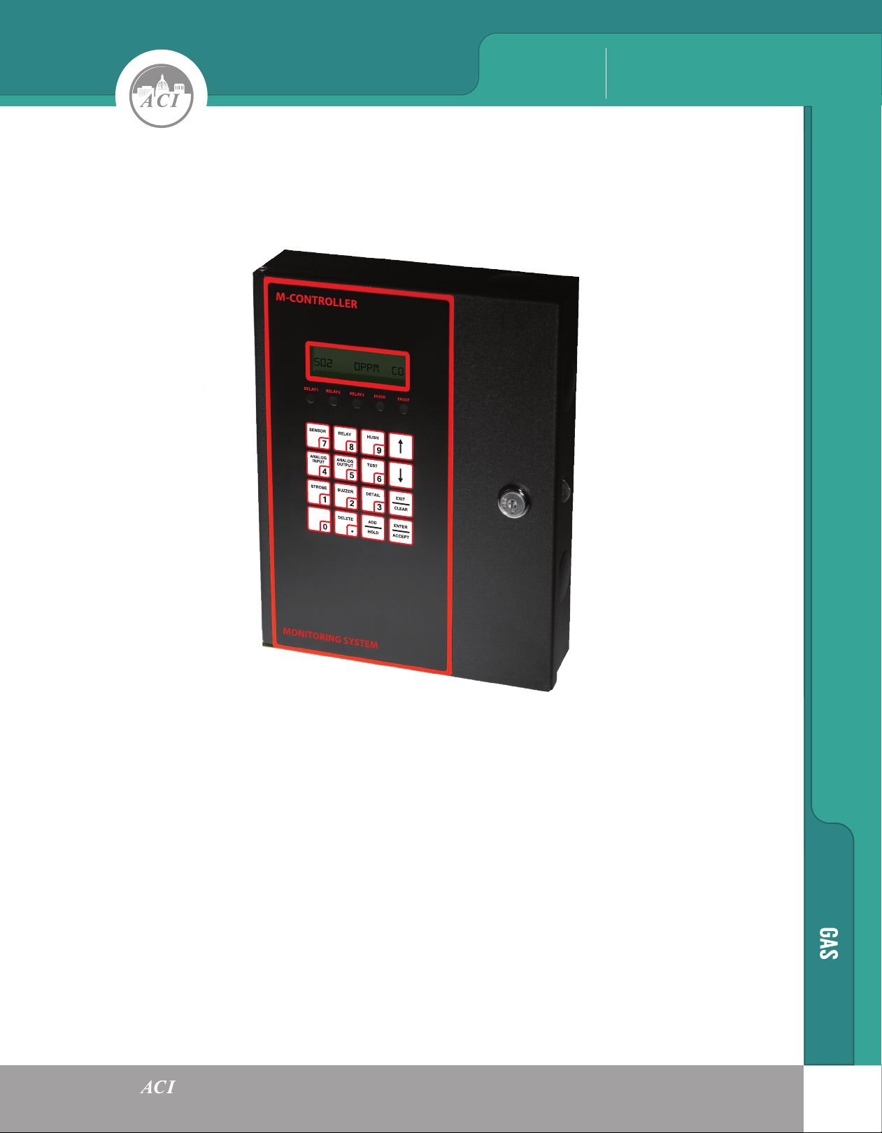
M-CONTROLLER
Multi-Channel Digital-Analog Controller
The M-Controller is a multi-channel controller and alarm unit. It utilizes both digital and analog
communications to interface with a maximum of 32 remote digital transmitter/sensors, and 8 analog
transmitter/sensors. Range and alarm setpoints are set either through the front keypad or through
software that is downloaded to the controller from a PC or laptop computer. Common relay configurations
include voting, averaging, delay on actuation and deactuation, normally/not-normally energized and
latching. An additional feature includes 24 VDC transistor outputs for a horn and strobe. A RS-422
responds as a RTU Slave using MODBUS protocol which allows the controller to provide read status
information only. The RS-232 interface uses a RJ-11 telephone jack. This is primarily used for uploading
and downloading a large configuration database. Also available is an analog output card that includes eight
4-20 mA analog outputs. Each analog output can be defined in complex fashions allowing the averaging of
several input signals and the assignment of different values to both the 4 and 20 mA outputs. The
M-Controller automatically linearizes the values between these two points.
Automation Components, Inc.
109
Page 2
GAS M-CONTROLLER
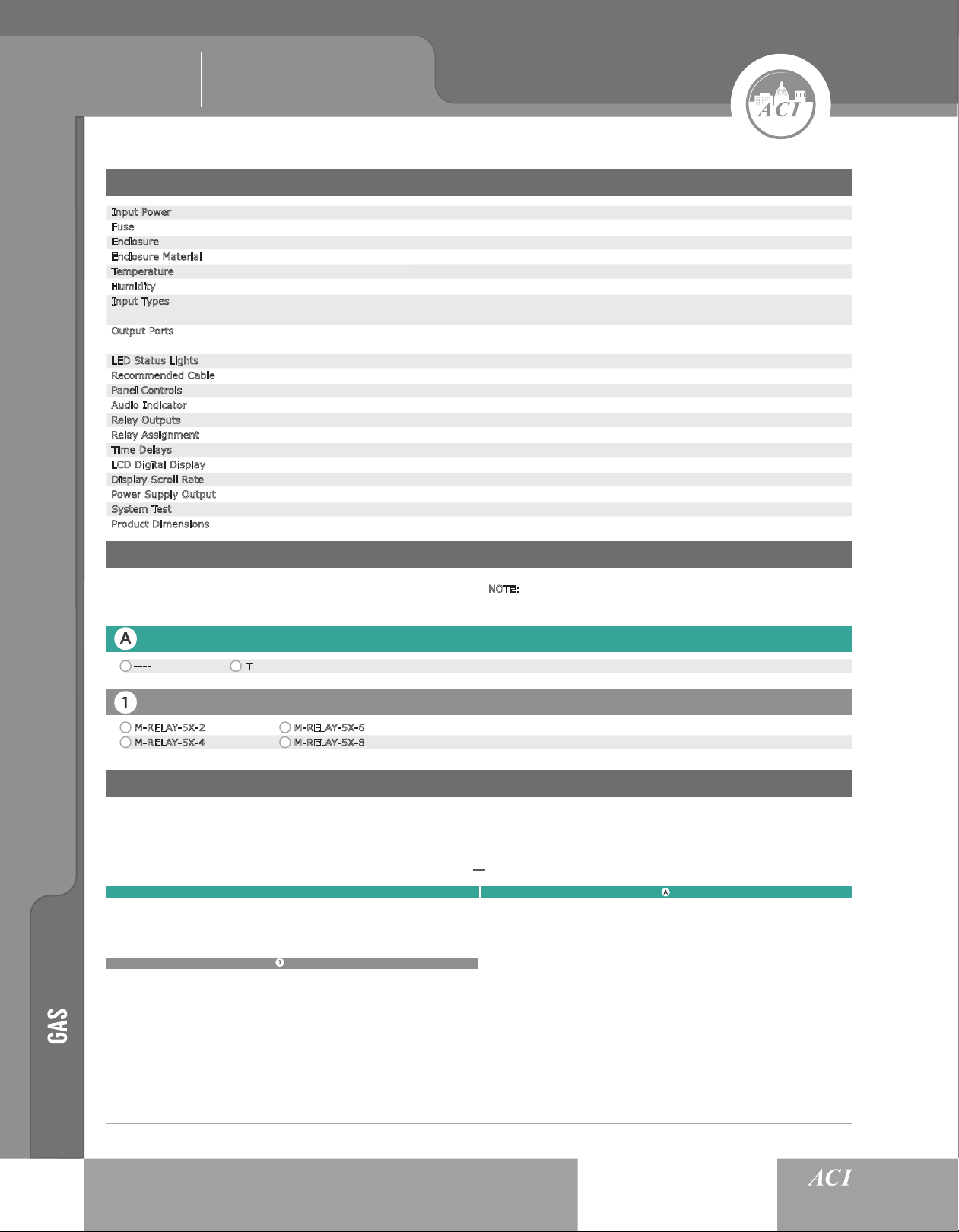
SPECIFICATIONS
Automation Components, Inc.
Input Power
Fuse
Enclosure
Enclosure Material
Temperature
Humidity
Input Types
Output Ports
LED Status Lights
Recommended Cable
Panel Controls
Audio Indicator
Relay Outputs
Relay Assignment
Time Delays
LCD Digital Display
Display Scroll Rate
Power Supply Output
System Test
Product Dimensions
24V +/- 4V AC or DC
2A
NEMA 1 Type General Purpose
Steel, epoxy painted black
Industrial -20° to 50° C (-4° to 122° F)
Continuous 15 to 90% RH, non-condensing Intermittent 0 to 99% RH, non-condensing
4 parallel RS-485 digital ports for up to 32 QEL transmitter/sensors, 99 Relays, 8 analog 4-20 mA inputs from any
transmitter/sensors. RS232 programming port using RJ-11 connector
RS-422 to host computer/PLC using Modbus Plus RS-232 programming port using RJ-11 connector optional 8 analog
4-20 mA signals scalable
5 Red, Relay 1, Relay 2, Relay 3, Hush, Fault
Power: Twisted shielded pair Communication (RS-485) Belden 9841 or equivalent twisted shielded pair, 120 ohm
4 x 4 tactile and audible keypad
90 db at 30 cm, 2700 Hz, Buzzer 1: Continuous Buzzer 2: Double-tap Intermittent, Buzzer 3: Intermittent 50% Duty Cycle
3 DPDT rated 5A resistive 3.7A inductive at 240 VAC/30 VDC, Optional 96 DPDT 5A relays 8 per card
Independent, individually set to one or all transmitter/sensors. Fail common to all transmitter inputs
Individually set, make, break, average, and voting, 0 to 60 minutes
Two line 16 character back-lit LCD displaying transmitter address, gas type, concentration and alarm status
Adjustable 1-9 seconds
24V supplied externally through controller
Through front keypad
(H) 10.00” (W) 8.00” (D) 2.00”
ORDERING
Please select a one Card (A). Choose an Optional Accessory (1) if desired. NOTE:
will be listed separately on packing slip and invoice.
Card
Additional relays are only available with M-RELAY-5X and they
---- (No Card)
T (Analog Card (8 Channels))
Optional Accessories
M-RELAY-5X-2 (2 Relays)
M-RELAY-5X-4
(4 Relays)
M-RELAY-5X-6 (6 Relays)
M-RELAY-5X-8
(8 Relays)
BUILD PART NUMBER
After completing (A) & (B) from the above table, fill in the Part Number Table below. The “Sensor Series” is a factory default. An example
part number is offered.
M-CONTROLLERX
SENSOR SERIES
EXAMPLE: M-CONTROLLERX - T
EXAMPLE: M-RELAY-5X-6
110
 Loading...