

Page 1
Installation and Operation Instructions
GP Series with 4-20mA Output
READ THESE INSTRUCTIONS BEFORE YOU BEGIN INSTALLATION
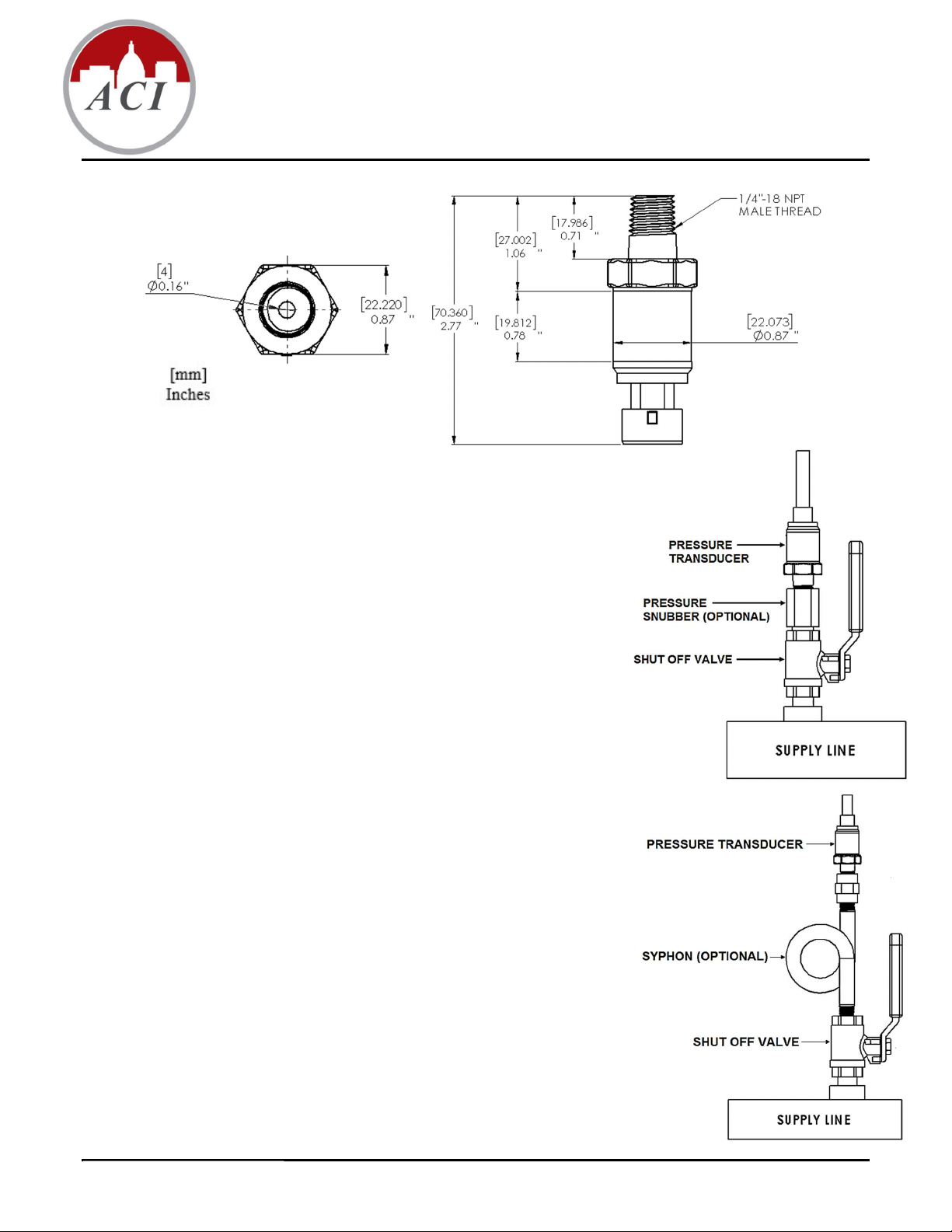
Figure 1
Product Description
The GP Series pressure sensor is a 4-20mA current output device that is
designed to provide excellent accuracy and reliability in commercial, industrial, and
process control applications where performance is critical. The GP Series is available
in two pressure sensing types: Gage (PSIG) and Sealed Gage (PSIS). Gage sensors
(PSIG) measure pressure relative to ambient pressure through a port that is open to
the atmosphere, and are used in lower pressure applications where measurement in a
vacuum is not required. Sealed sensors (PSIS) measure pressure relative to a port that
is connected to a sealed perfect vacuum chamber. Sealed pressure transducers are
calibrated to have 4 mA at +14.5 PSIA.
Optional Accessories
Pressure Snubber
ACI recommends the use of the A/0.25” Snubber (Water or Air/Gas) with all GP
series sensors. The use of a pressure snubber is a cost-effective solution that can
extend the life of your sensor by smoothing out pressure spikes, surges and
pulsations, and prevent debris from collecting in the sensor diaphragm opening.
The A/0.25” Snubbers are made of 316 Stainless Steel and should be used with
compatible materials.
Syphons
The A/Syphon must be used to protect the sensor from extreme operating
temperatures when the operating temperature of the steam being monitored is higher
than the maximum operating temperature of the GP pressure sensor. There are three
bend configurations available (90˚, 180˚, and 270˚) to allow the mounting of the
sensor vertically away from the main pipe.
NEMA 4 Enclosure
ACI recommends the use of a NEMA 4 enclosure to protect the gage pressure sensor
in applications where debris and moisture could contact the sensor or electrical
connections. The A/GP-(xx)-NEMA 4 GP Series pressure sensor is mounted in a
NEMA 4 Rated, steel enclosure with one ½” conduit knockout. A ¼” male NPT
Stainless Steel fitting is provided for installation to your pipe, tank, or reservoir.
Media Compatibility
The bulk micro-machined transducer features a stainless steel diaphragm with
welded construction that contains no O-rings, which makes them compatible with
any gas or liquid that’s compatible with 304L stainless steel. Some compatible
gasses and liquids include refrigerants, glycol, motor oil, diesel, hydraulic fluid,
brake fluid, water, waste water, hydrogen, nitrogen and air.
Version : 6.0
Page 1 of 2 I0000230
Figure 2
Figure 3
Page 2
Installation
Location
Install the sensor in a location where it will not be exposed to extreme temperatures, vibration or shock. Install the pressure
sensor above or on the side of pipes, in a location where liquid will not drip on the unit. Condensation can potentially build
up and run down the harness, position the unit and harness so water does not pool on the back of the sensor. Do not install
the sensor at the end of a long run of pipe.
Connection
The GP uses a standard ¼”-18 NPT external fitting. Standard pipe fittings and installation procedures should be used during
installation. Install pipe tape, thread sealant or other suitable pipe compound when connecting the sensor to the pressure
source or any of the accessories. For pressure ranges more than 500 PSI (3447.4 kPa), we recommend the use of a sealant
such as Loctite Hydraulic Sealant. Do not use excessive amounts of sealant or you might block the pressure going into the
transducer. Install the device using a wrench on the hex flats provided. Do not use a strap wrench on the body. When
installing the GP sensor, the torque limit is 150 in lbs (16.95 Nm), Do Not over tighten. Overtightening metal fittings may
cause a slight zero shift. The use of plastic fittings typically results in no noticeable zero shift. The torquing effect does not
appreciably affect linearity or sensitivity. In liquid pressure monitoring applications, air present in the lines will cause erratic
readings, use bleed fittings to bleed off any air that has been trapped before transducer installation.
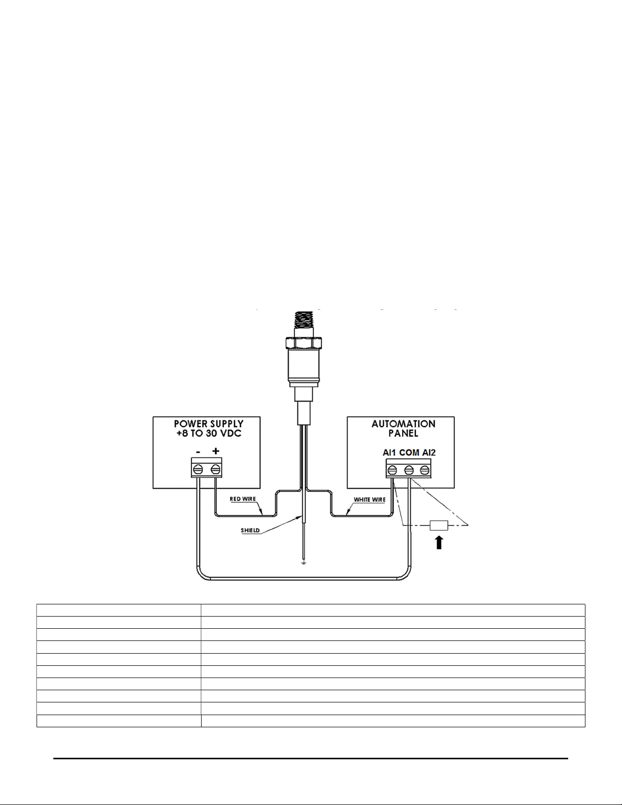
Electrical Connections
The transducer requires a supply voltage of +8 to 30 VDC with a minimum supply current of 25 mA (per unit) to power the
loop. The transducer is equipped with a Packard connector for easy installation, and is designed for use with the GP Harness.
Install the GP Sensor onto the harness then make the proper connections to the harness. Connect the Power lead (Red) to
the plus terminal of the supply voltage. Connect the Return lead (White) to the plus terminal of the current measuring
device(controller). Connect the minus terminal of the current measuring device to the minus terminal of the supply voltage,
and the Shield Wire should be connected to the system or earth ground. See Figure 4, wiring diagram.
AI1/AI2= 4 to 20mA
Analog Input
Optional 250 Ohm or 500 Ohm
Load Resistor for a 1-5 VDC or
2-10 VDC Output.
Figure 4
General Specifications
Supply Voltage: 4-20 mA Output: +8 to 30 VDC | 250 Ohm Load: +13 to 30 VDC | 500 Ohm Load: +18 to 30 VDC
Supply Current: 25 mA minimum
Output Signal: 4 to 20 mA (2-Wire, Loop Powered)
Proof Pressure 15 to 300 PSIG: 3x FS | 500 PSIS: 3x FS
Burst Pressure: 15 to 300 PSIG: 3x FS | 500 PSIS: 3x FS
Accuracy¹ @ 22˚C (71.6˚F): 15 to 60 PSIG: < +/- 1.0% FS | 75 to 300 PSIG: < +/- 0.5% FS | 500 PSIS³: < +/- 0.5% FS
Thermal Error² (-40˚ to 105˚C) 15 to 60 PSIG: < +/- 1.0% FS | 75 to 300 PSIG: < +/- 0.5% FS | 500 PSIS³: < +/- 0.5% FS
Stability (250 Hours @ 225˚F (125˚C)): +/- 0.03% FS @ 0 PSIG; +/- 0.12% FS @ 1000 PSIG
Operating | Storage Temperature: -40 to 221˚F (-40 to 105˚C) | -40 to 176˚F (-40 to 80˚C)
Process Fitting Material | Thread Size: 304L Stainless Steel | 1/4"-18 NPT
Note 1: Accuracy includes Hysteresis, Repeatability, and Non-linearity (BFSL) Note2: Additional error over temperature range
Note 3: PSIS transducers are not vented to atmosphere, but are calibrated to have 4 mA at +14.5 PSIA
Version : 6.0
Page 2 of 2 I0000230
 Loading...