

Page 1
ACI
ACI
Automation Components, Inc.
TRANSMITTER/SENSOR
CTS-M5
TOXIC GAS
INSTALLATION
OPERATION AND MAINTENANCE
MANUAL
Page 2

M-5 Operation And Maintenance Manual
Relay 1 (Warning)
Relay 2 (Alarm)
4 mA
CTS-M5 Configuration:
Default Settings
Settings Settings
1. Signal 4 mA See Table Below ________________
20 mA See Table Below ________________
2. Password 0017 ________________
3.* Relay 1 Actuation Enabled ________________
4. Relay 1 Setpoint (Actuation) See Table Below ________________
5. Relay 1 Release Point See Table Below ________________
(De-Actuation)
6. Relay 1 Actuation Delay 0 Minutes ________________
7. Relay 1 De-Actuation Delay 0 Minutes ________________
8.* Relay 2 Actuation Enabled ________________
9. Relay 2 Setpoint (Actuation) See Table Below ________________
10. Relay 2 Release Point See Table Below ________________
(De-Actuation)
11. Relay 2 Actuation Delay 0 Minutes ________________
12. Relay 2 De-Actuation Delay 0 Minutes ________________
13 Communication Protocol Optomux ________________
14. Digital Address 0001 ________________
15 Baud Rate 4800 ________________
Factory User
Note: Relay setpoints are included in the software; however relays are optional.
Gas Type
NO2 0 ppm 6.0 ppm 1.0 ppm 0.8 ppm 3.0 ppm 2.5 ppm
CO 0 ppm 125 ppm 25 ppm 20 ppm 50 ppm 40 ppm
NO 0 ppm 100 ppm 25 ppm 20 ppm 50 ppm 40 ppm
NH3 0 ppm 50 ppm 25 ppm 20 ppm 35 ppm 30 ppm
O2 0% 25%
83850-001-000 RG Aug 06, 2013
Default
20 mA
Default
(If Applicable)
Setpoint Release Point Setpoint Release Point
19.50%
Decreasing
20.00%
(If Applicable)
23.00%
Increasing
22.00%
1
Page 3

M-5 Operation And Maintenance Manual
Table Of Contents
Default Settings...........................................................................................................................................1
1. PRINCIPLES OF OPERATION ........................................................................................................3
1.1
D
ISPLAY
.............................................................................................................................................3
1.2
K
EYPAD AND FUNCTION CONFIGURATION
1.3
P
ASSWORD
1.4
O
UTPUT SIGNALS
1.5
M
ETER JACKS
1.6
S
IGNAL AND DISPLAY RANGE
1.7
O
PTIONAL RELAY PACKAGE
1.8
D
EFAULT CONDITIONS
1.9
S
ENSING AND CALIBRATION
1.9.1 Calibration ...................................................................................................................................5
1.9.2 Implications for Troubleshooting .................................................................................................5
2. FUNCTION AND CONFIGURATION .............................................................................................6
2.1
M
ENU STRUCTURE AND USE
2.2
C
ONFIGURATION AND CALIBRATION
2.3
H
ARDWARE CONFIGURATION
2.3.1 Output Signals ............................................................................................................................13
2.3.2 RS-485 End-of-Line Wiring and Termination ............................................................................13
2.3.3 Battery ........................................................................................................................................14
2.4
G
AS CALIBRATION
2.4.1 Equipment Required ...................................................................................................................14
2.4.2 Procedure ...................................................................................................................................15
2.4.3 Calibration Errors......................................................................................................................15
.........................................................................................................................................4
...............................................................................................................................4
....................................................................................................................................4
............................................................................................................4
...............................................................................................................5
.......................................................................................................................5
...............................................................................................................5
..............................................................................................................6
...........................................................................................................13
...........................................................................................................................14
.........................................................................................3
..................................................................................................7
3. FAULTS..............................................................................................................................................16
3.1
S
ELF-CHECK FAULTS
3.2
H
ARDWARE FAULTS
4. WIRING AND POWER SUPPLIES ................................................................................................19
........................................................................................................................16
.........................................................................................................................18
83850-001-000 RG Aug 06, 2013
2
Page 4
M-5 Operation And Maintenance Manual
CTS-M5 Operating Manual
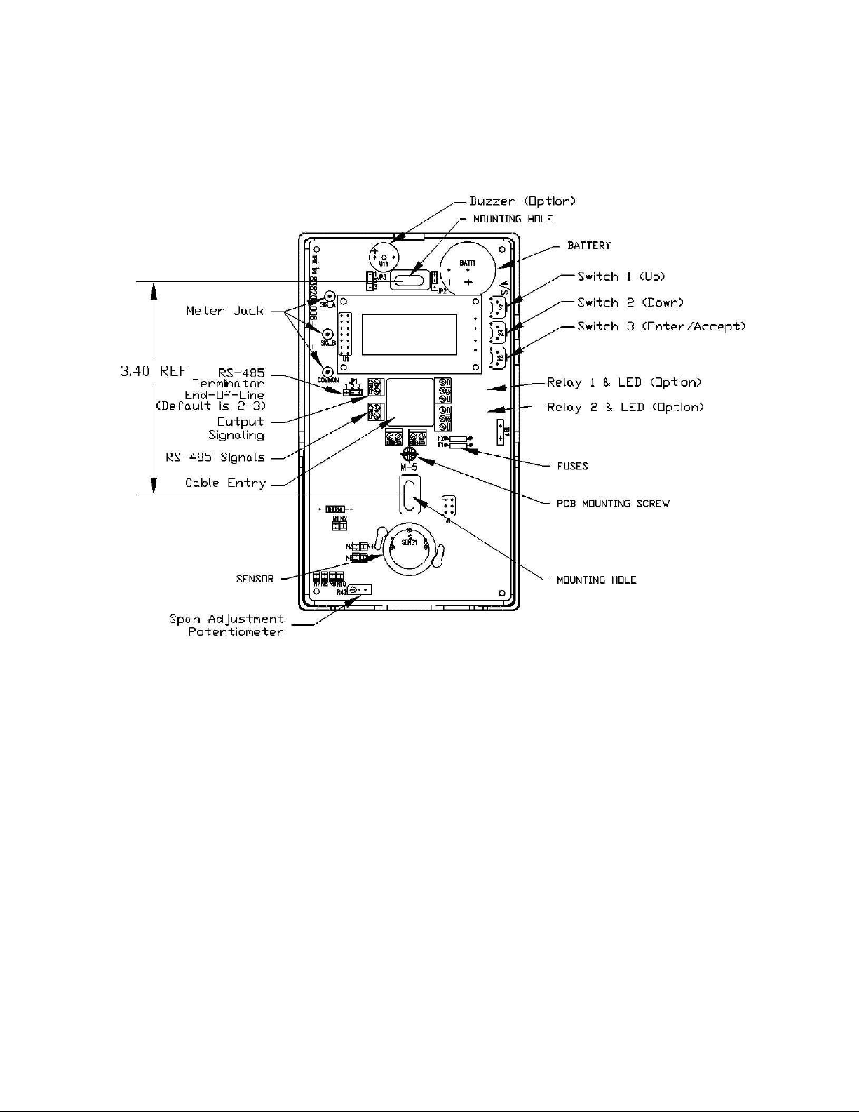
1. Principles of Operation
Figure 1 CTS-M5 Internal View - Features
1.1 Display
The display module is a 2-line by 8-character LCD. Standard reading in operation is
Gas Type
xxx Units
1.2 Keypad and Function Configuration
Relay settings and other configurable items are accessed through the keypad and menu
display.
The keypad is a set of 3 buttons recessed along the upper right side of the enclosure. It is
not necessary to open the cover for use of the keypad. Access to the menus is password
restricted. Press any key for 3 seconds to enter the menus. (See below for details)
83850-001-000 RG Aug 06, 2013
3
Page 5

M-5 Operation And Maintenance Manual
1.3 Password
Factory preset default password is 0017.
Password can be changed. RECORD PASSWORD IN A SECURE PLACE. If the
password is lost, the unit must be returned to QEL to be reset
1.4 Output Signals
Options are 4-20 milliamp or 2-10 VDC linear. Choose the option by moving the jumper
on JP3. On over range concentrations the signal can exceed the range slightly.
Figure 2 Signal Configuration JP3
I
MPORTANT
: Voltage monitoring should be into a monitor with at least 50 000 ohms
input impedance. Voltage monitoring is not recommended over long distances, as
these signals are more susceptible to induced noise than current signals
1.5 Meter Jacks
Test pads accepting standard test probes are provided on the circuit card. These are
labeled SigA, SigB and Common
To test milliamp signals measure:
• SigA to Common shorts to internal ground.
• SigA to SigB without interrupting signal to monitor
To Test voltage signals measure:
• SigB to Common.
1.6 Signal and Display Range
It is important to distinguish between Signal Range (often called Span) and Display
Range.
83850-001-000 RG Aug 06, 2013
4
Page 6

M-5 Operation And Maintenance Manual
Display Range is the range of concentrations the unit is capable of displaying
(which is the same concentration it will report on the digital communications).
The display range varies with the gas type.
Signal Range is the assignment of the 4 to 20 mA signal. Default assignment of 4
mA is zero concentration. The default setting for 20 mA varies with the gas type.
The Signal range is fully adjustable within the limits imposed by the Display Range. Both
the 4 mA level and the 20 mA level can be reassigned through the menu system. Please
note that this adjustment does not change the measurement resolution.
1.7 Optional Relay Package
Two relays are supplied; single pole double throw (SPDT; Form C) 1 Amp. Dry contacts
only. Configuration allows setpoint adjustment for actuation point, dead-band, and
delays, increasing or decreasing concentrations. The relay settings have the same range as
the Display Range, and are independent of Signal Range.
1.8 Default Conditions
Default conditions are those conditions, which occur:
• During the short wait state on Power On.
• In Fault status.
• In the menu tree.
In these situations the following conditions hold:
• Signal set at 4.0 milliamps (2 Volts)
• Relays set non-energized.
• Digital communications report 0; no alarm status and 4 milliamp equivalent
signal.
1.9 Sensing and Calibration
Sensor type: Various electrochemical.
1.9.1 Calibration
The sensor is strongly linear in it’s response to gas. It is therefore straightforward to
calibrate. Two gases are needed for calibration: Zero gas (clean air) and an appropriate
span gas. Adjustment is by one potentiometer on the circuit board.
1.9.2 Implications for Troubleshooting
The microprocessor will detect various component faults and out-of-range conditions,
and drop the output signal to 0.0 milliamps. When a fault is detected, both relays will be
deactivated as well. However, it cannot detect simple out of calibration conditions, which
can only be detected by applying a gas standard.
83850-001-000 RG Aug 06, 2013
5
Page 7

M-5 Operation And Maintenance Manual
2. Function and Configuration
2.1 Menu Structure and Use
Note: While the keypad functions are available without opening the case. It is necessary
to open the case to apply the calibration gases. The ‘keypad’ switches are located in the
upper right side of the enclosure. See Figure 1 Page 3.
Display: The display is 2 line by 8 character alphanumeric. The top line contains the
feature name and the second contains the variable.
Keypad: The keypad consists of three (3) pushbutton switches.
S1 Scroll Up
S2 Scroll Down
S3 Enter/Accept
Display at Turn-On:
The display shows the following for about 2 seconds:
QEL M-5
Vx.xx Ry
Where: x.xx = the Software Version
y = the Software Revision
Followed for about 2 seconds by:
ElectrCh
Vx.xx Ry
Where: ElectrCh = Electrochemical
x.xx = the Sensor Algorithm Version
y = the Sensor Algorithm Revision
Display in Operation: The display shows
GAS
xxx Units
Where GAS will show the target gas, and xxx is concentration of
the gas. Units may be either ppm (parts per million) or %.
83850-001-000 RG Aug 06, 2013
6
Page 8

M-5 Operation And Maintenance Manual
Range
(Relay 1)
(Relay 2)
Default
Note: Should the concentration equal or drop below an internal
value, the unit will flash "CALIBR" on display line 2 every 8
seconds.
Menu Activation: Press and hold any key for 3 seconds to enter the menu tree.
Menu Scrolling: Use the scroll buttons to scroll up and down through the menu tree.
Data Entry Mode: Enter the data entry mode by pressing S3 (Enter) while displaying
any feature. This mode is indicated by an * (asterisk) at the right of the variable, and
indicates that the variable may be changed by scrolling. Press S3 (Accept) to save result
and return to menu tree. While in data entry mode, the Up and Down keys perform an
automatic key repeat while the key is held in.
Password: The first item on entering the menu tree is a Password request. The display is
0000, the default password is 0017. The * appears, indicating that a number can be
entered and accepted. This number can be changed by the user (see below).
Fault: In case of faults, the display will read FAULT and a fault code in the bottom LCD
line (see below). Signal will drop to 0 milliamps.
See section 3 below for more information on faults.
2.2 Configuration and Calibration
Gas Type Display
Warning
W-Deact Alarm
A-Deact 20 mA
NO
CO 0-250 ppm 25 ppm 20 ppm 50 ppm 40 ppm 125 ppm
NO 0-200 ppm 25 ppm 20 ppm 50 ppm 40 ppm 100 ppm
NH
0-10.0 ppm 1.0 ppm 0.8 ppm 3.0 ppm 2.5 ppm 6.0 ppm
2
0-100 ppm 25 ppm 20 ppm 35 ppm 30 ppm 50 ppm
3
2
0-25 % 20.00% 22.00%
19.50% 23.00%
Decreasing Increasing
25%O
Note: The user has control of all variables, including calibration gas concentrations,
alarm settings and signal range (both 4 milliamp and 20 milliamp) assignments. It is
important to note that these must be chosen carefully with regard to calibration. Zero
calibration is done through a menu option, Span calibration is done though a
potentiometer on the circuit card, not through the menu system, and so it is possible to
perform the adjustment without the menu system; however, the menus do offer disabling
of output actuation.
1. Press any key for 3 seconds to enter menu system
83850-001-000 RG Aug 06, 2013
7
Page 9

M-5 Operation And Maintenance Manual
2. Password Control
PASSWORD
0000 *
Press up/down to choose correct password and accept.
3. Factory Settings Sub-menu Branch
FACTORY
Settings
This function is for factory setup and test only.
4. Relay 1 Sub-menu Branch
RELAY 1
Settings
Press Enter to proceed to the Relay 1 Settings sub-menu (press down/up to skip
Relay 1 Settings and go to next/previous menu item or sub-menu).
4.1 RELAY
Enable
Press Enter to change. “*” Indicates to use scroll buttons to toggle between
Enable, Disable or Latching. Press Accept when done.
Note that this disables the physical relay, but not the setpoint. Setpoint
actuation status will still be transmitted on the digital communications link
if queried.
When the “Latching” option is selected, the relay will not de-actuate
unless it is cancelled by pressing one of the keyboard buttons. The relay
will only reset if the alarm situation has dissipated.
Enable is the default.
Press Down button to continue through Relay 1 Settings branch. Press Up
to return to Main Menu (and Relay 1 Settings sub-menu branch).
4.2 Actuation Setpoint
ACTUATE
00XX ppm (or %)
83850-001-000 RG Aug 06, 2013
8
Page 10

M-5 Operation And Maintenance Manual
Choose the concentration of Gas. Up/Down scrolls up/down in the Relay 1
Settings branch.
4.3. De-Actuation Setpoint
DEACT
00XX ppm (or %)
Choose the concentration of the gas at which you want the alarm condition
to stop.
Note: If the De-Actuation Setpoint is set at a higher concentration
than the Actuation setpoint, then the setpoint function reverses and
actuates on decreasing concentrations.
Note: The software will not allow the user to set Actuation = De-actuation.
If Actuation is set equal to De-actuation, the Actuation Setpoint will be
adjusted upward by 10% of display range automatically before saving the
new settings.
4.4 Actuation Delay.
ACT-TIME
00 min
Adjust the amount of time delayed before the relay is actuated after the
Actuation Setpoint is reached. A maximum of 60 minutes is possible,
adjustable in 5-minute increments.
Default is 0000.
4.5 De-Actuation Delay.
DEACTIME
00 min
Adjust the amount of time delayed before the relay is released after the DeActuation setpoint is reached. A maximum of 60 minutes is possible,
adjustable in 5-minute increments. Default is 00.
4.6 Buzzer.
BUZZER
83850-001-000 RG Aug 06, 2013
9
Page 11

M-5 Operation And Maintenance Manual
Disable (or Enable)
The internal buzzer can be activated together with Relay 1 if ‘Enable’ is
selected. The buzzer is silenced by pressing any of the key buttons during
normal operation. Selecting ‘Disable’ only disables the buzzer activation
for Relay 1. Buzzer operation respective to Relay 2 is set in the ‘Relay 2
Settings’ Sub-menu.
Note: If the buzzer is enabled for any of, or both the relays, the first key
press will silence the buzzer (buzzer acknowledge) and a second key press
is needed if any, or both of the relays is set for ‘Latching’ mode. Refer to
3.1 above.
To configure the buzzer for Relay 2 operation, go the ‘Relay 2 Settings’
sub-menu.
Default is Disabled.
The Up key scrolls back up the Relay 1 Settings sub-menu branch. The
Down key leaves the Relay 1 Settings sub-menu branch and returns to the
Relay 1 Settings main menu item.
5. Relay 2 Sub-menu Branch
RELAY 2
Settings
Press Enter to access the settings. The sub-menu structure is the same as
for Relay 1 Settings.
6. Range Adjustments
CONC4MA
0000 ppm (or %)
This feature allows adjustment of the 4 milliamp point to non-zero gas
concentrations. The display will always read as low as 0000, but the concentration
corresponding to 4 milliamps changes.
Maximum: Display Range
Minimum: 0
Note: An inverted response at the signal output can be achieved by setting
CONC4MA higher than CONC20MA.
83850-001-000 RG Aug 06, 2013
10
Page 12

Note: Changing the range in this fashion does not enhance the gas measurement
accuracy.
7. Range Adjustments
CONC20MA
0XXX ppm (or %)
This feature allows adjustment of the 20 milliamp point to different gas
concentrations. The display will always read as low as the maximum for that gas
but the concentration corresponding to 20 milliamps changes. Note that the
display maximum is not affected by this adjustment.
Maximum: Display Range
Minimum: 0
Note: An inverted response at the signal output can be achieved by setting
CONC4MA higher than CONC20MA.
Note: changing the range in this fashion does not enhance the gas measurement
accuracy.
Note: The software will prevent the user from setting the 4mA point = 20mA
point. In such a case, the 20mA point will be lifted by 10% of Display Range
before saving the settings.
8. Calibration:
8.1 Calibrate Zero Gas
CAL ZERO
000 ppm (or %)
Apply Zero Gas (clean air). Wait to stabilize. Press Enter. The unit will
automatically reset the display to 000.
8.2 Calibrate Span
Calibration is done with the potentiometer on the circuit card, not through the
menu system, and so it is possible to perform the adjustment without the menu
system; however, the menus do offer disabling of output actuation.
CAL SPAN
XXX ppm (or %)
M-5 Operation And Maintenance Manual
83850-001-000 RG Aug 06, 2013
11
Page 13

M-5 Operation And Maintenance Manual
Calibration Procedure:
Apply an appropriate span gas, and adjust the Gain potentiometer to get the
correct reading on the display.
Press Up/Down to go to the next/previous menu item.
9. Communications Protocol
PROTOCOL
Optomux
The Optomux protocol (default) communicates with QEL's M-Controller.
The B4000 protocol communicates with QEL’s QDC-4000 monitor.
Press Enter and Up/Down to select the desired protocol.
10. Digital Address
ADDRESS
0001
Allows changes to the digital communications address for the transmitter.
Note: The new address is available immediately it is accepted at this point, and
the unit will respond to only this address when queried even though you are still
inside the main menu tree. If you abort the main menu tree (see below) then the
address will revert to the previous address.
Optomux maximum: 256
B4000 maximum: 16
Note: If the B4000 protocol was selected (above), all previously set addresses
higher than 16 will be folded back to address 16.
11. Baud Rate
BAUDRATE
4800
Default is 4800 baud.
Options: 600, 1200, 2400, 4800 and 9600
12. Change Password
83850-001-000 RG Aug 06, 2013
12
Page 14

PASSWORD
0000
Factory default is 0017.
Press Enter and scroll up and down to choose a new password. RECORD
PASSWORD IN A SECURE PLACE.
Note: This item displays the current password, so it is important to keep security
in mind when passing this item in the presence of bystanders.
If the password is lost, the unit must be returned to QEL to be reset.
13. Exit Menu Tree
EXIT
Save
Press Enter, an * will appear beside Save. Press Up/Down to choose Save or
Abort. Press Enter/Accept to exit.
Note: Choosing Abort will discard all changes made since last entering the menu
system, including calibration values.
M-5 Operation And Maintenance Manual
2.3 Hardware Configuration
2.3.1 Output Signals
Options are 4-20 milliamp or 2-10 V linear. Choose the option by moving the jumper on
JP3. On over-range concentrations the signal can exceed the range slightly.
Figure 3 Signal Configuration
2.3.2 RS-485 End-of-Line Wiring and Termination
RS-485 installations require specialized wiring. A number of manufacturers make cable
especially for this wiring standard (EIA-485), (e.g. Belden 9841). This is a twisted,
shielded, balanced pair, 24 AWG, 120 Ohm. In order to prevent signal bounce-back and
83850-001-000 RG Aug 06, 2013
13
Page 15

M-5 Operation And Maintenance Manual
other distortions, it is necessary to provide a balancing resistor across both ends of the
wire. The M-5 supplies this resistor on board, and it is chosen using a jumper at JP1.
JP1
1 2 3
JP1
1 2 3
Figure 4 RS-485 End-of-Line Termination
2.3.3 Battery
Certain sensors (NH3, NO) require active power even when the unit as a whole is
powered down. This is done to prevent excessively long stabilization periods on turn-on.
Disable the battery using JP2 when the unit is powered down without a sensor cell
present. The battery is not consumed when the unit is powered.
Terminator Selected
Terminator Open
(default)
Figure 5 Battery Connection Enable
2.4 Gas Calibration
Calibration should not vary significantly over a period of years; however, it is best to
perform a verification calibration after installation, and at one-year intervals thereafter.
All units are factory calibrated.
2.4.1 Equipment Required
• Zero air, (clean air or nitrogen).
• Appropriate span gas as close to the range of interest as possible
• Pressure and Flow Limiting Regulator(s) 0.4 to 0.8 lpm (0.8 to 1.6 scfh)
• Tubing and bayonet adapter.
83850-001-000 RG Aug 06, 2013
14
Page 16

M-5 Operation And Maintenance Manual
Figure 6 Calibration Gas Bayonet Adapter
2.4.2 Procedure
Calibration Procedure:
Enter the configuration menu system and proceed to “CAL ZERO”.
This disables alarm outputs, and forces the output signal to 4.00 milliamps.
Response of these sensors to gas varies with the sensor, but in most cases the
signal should be sufficiently stable in less than 5 minutes. Pre-calibration
stabilization times vary from 24 hours (CO and NO2) to a week or more (NH3).
Apply zero gas (clean air) and wait for the display reading to stabilize.
(Remember that the 4-20 milliamp signal may be set to a different range.) Press
Accept to automatically zero the reading.
Press Down to go to CAL SPAN.
Apply an appropriate span gas, and adjust the Gain potentiometer to get the
correct reading on the display.
On removing the gas, you may find that the display does not completely re-zero.
Return to CAL ZERO to re-Zero. Note: Allow enough time for the sensor to
stabilize at zero in order not to set an incorrect zero calibration.
2.4.3 Calibration Errors
If the gas flow was not sufficient, or the bayonet adapter was too loosely applied, the gas
concentration in the sensor will stabilize at an incorrect low value.
83850-001-000 RG Aug 06, 2013
15
Page 17

M-5 Operation And Maintenance Manual
3. Faults
3.1 Self-check Faults
The microprocessor monitors a number of operational values for faults, and will display
each occurrence for two seconds as follows:
FAULT
XXX
Where XXX is a fault code.
The unit will automatically restart and continue normal operation if the fault occurred due
to a temporary intrusion (e.g.: Radio frequency interference or water condensation formed
due to fast temperature change).
A fault shown repeatedly indicates malfunction of the unit. In such cases the fault code
should be recorded and the unit returned for repair.
When a fault is detected, the output is dropped to 0.0 mA and both relays are deactivated.
The only Self Check Faults which can be field addressed are those which refer to
problems with the sensor (fault code 048):
• Check that the sensor is inserted in its socket correctly.
• Replace sensor. If the fault is removed, then re-calibrate.
• Return unit to Factory.
Beep Codes:
One short beep, followed by 5-second silence, accompanied by blank LCD, indicates a
faulty LCD, return to factory for repair.
Note: The unit performs a standard short beep at power-up.
83850-001-000 RG Aug 06, 2013
16
Page 18

M-5 Operation And Maintenance Manual
FLASH EEPROM verify error when writing.
mplete.
Driven output higher than monitored output.
Fault Codes:
Fault Code Description Action
Audible
001 LCD Fault (1 beep, 5 second silence) Return unit to factory for repair if
EEPROM
008 FLASH EEPROM write time-out.
009 Data EEPROM write time-out.
010
011 Data EEPROM verify error when writing.
012 Last EEPROM write interrupted, inco
Analog Output Signal
032
033 Driven output lower than monitored output.
034 Voltage output load too large (or mode fault).
035 Voltage output load driving into unit.
System
024 Out of ms timers.
025 Out of second timers.
026 Message queue overflow.
Sensor
040 Sensor front-end or heater driver fault.
041 Pseudo ground level too low.
042 Pseudo ground level too high.
Calibration
048 Concentration too far negative. Calibrate.
Mathematics
056 32-bit scale operation overflow. Calibrate.
057 Floating-point overflow.
058 Floating-point underflow.
059 Floating-point divide by zero.
060 Floating-point domain error exception. Calibrate.
fault persists.
Return unit to factory for repair if
fault persists.
Return unit to factory for repair if
fault persists.
Return unit to factory for repair if
fault persists.
Check sensor, replace sensor and
calibrate.
Return unit to factory for repair if
fault persists.
Return unit to factory for repair if
fault persists.
Return unit to factory for repair if
fault persists.
Calibrate.
Return unit to factory for repair if
fault persists.
Calibrate.
Return unit to factory for repair if
fault persists.
Calibrate.
Return unit to factory for repair if
fault persists.
Return unit to factory for repair if
fault persists.
83850-001-000 RG Aug 06, 2013
17
Page 19

M-5 Operation And Maintenance Manual
3.2 Hardware Faults
Screen Blank, no Signal Check wiring, check fuses.
Distorted Milliamp Signal Output jumper set to voltage.
Voltage signal pinned high Output jumper set to milliamps
No milliamp Signal on AC floating power
supply
Bad RS-485 Communications for this unit. Check wiring polarity for A & B lines
Bad RS-485 Communications for a multi-drop
group.
Check for signal common line.
Check for signal operation by using on-board
test points
Check for correct line terminations.
Check for correct address.
Check for correct Baud rate and protocol.
Check wiring polarity for A & B lines
Check for correct line terminations.
It is possible for one failed device on a multidrop line to pull communication down for the
whole line.
Check for correct addresses, Baud rate and
protocol selection.
83850-001-000 RG Aug 06, 2013
18
Page 20

M-5 Operation And Maintenance Manual
4. Wiring and Power Supplies
The CTS-M5 Power Supply input is not isolated internally from the electronics and thus
the signal common. Therefore, while the power supplied may be AC or DC, care must be
taken to avoid the creation of multiple grounds (or a ground loop).
Figure 7 24VAC Floating Supply 4-Wire Installation
Figure 8 24VAC with Common Grounds - 3-Wire Installation
83850-001-000 RG Aug 06, 2013
19
Page 21

M-5 Operation And Maintenance Manual
Figure 9 24VDC Supply with Common Ground - 3-Wire Installation
Figure 10 RS-485 Connection
Figure 11 Relay Connections
83850-001-000 RG Aug 06, 2013
20
Page 22

M-5 Operation And Maintenance Manual
WARRANTY STATEMENT
The information contained in this manual is based upon data considered accurate; however, no
warranty is expressed or implied regarding the accuracy of this data. All QEL equipment is
warranted against defects in material and workmanship for a period of two years from date of
shipment with the following exceptions:
Electrochemical Sensors (Toxic) Six Months
Catalytic Sensors (Combustible) One Year
During the warranty period we will repair or replace, at our discretion, any components or
complete units that prove, in our opinion, to be defective. We are not liable for consequential or
incidental damage to auxiliary interfaced equipment.
A returned material authorization number should be obtained from the factory prior to returning
any goods. All return shipments must be shipped freight prepaid and a copy of the maintenance
records should accompany the unit concerned.
Warranty should be considered F.O.B. the factory. Labour and travel time are chargeable for any
field site visits required for warranty work.
LIMITED LIABILITY
All QEL systems shall be installed by a qualified technician/electrician and maintained in strict
accordance with data provided for individual systems in the form of installation/maintenance
manuals. QEL assumes no responsibility for improper installation, maintenance, etc., and
stresses the importance of reading all manuals. QEL shall not be responsible for any liability
arising from auxiliary interfaced equipment nor any damage resulting from the installation or
operation of this equipment.
QEL’s total liability is contained as above with no other liability expressed or implied as the
purchaser is entirely responsible for installation and maintenance of systems.
This warranty is in lieu of all other warranties, expressed or implied, and no representative or
person is authorized to represent or assume for QEL any liability in connection with the sales of
our products other than that set forth herein.
NOTE: Due to on-going product development, QEL reserves the right to change
specifications without notice and will assume no responsibility for any costs as a
result of modifications.
For further information or assistance, contact:
83850-001-000 RG Aug 06, 2013
21
 Loading...