

Page 1
BACnet IMMERSION SERIES
Installation & Operation Instructions
GENERAL INFORMATION
The BACnet Immersion Series sensor is designed for use
with electronic controllers in commercial heating and
cooling building management systems. The ACI BACnet
Immersion Series sensor can be ordered to monitor
temperature in commercial HVAC pipes. It uses BACnet
MS/TP for physical connection to a BAS or controller, has
dip switches to set addresses and baud rate, and has on
board end-of-line termination. There is no analog output.
WIRING INSTRUCTIONS
The BACnet Immersion Series temperature sensor has a
depluggable terminal block located on the front of the
PCB. For ease of wiring, we recommend removing the
block, wiring, and reattaching before mounting. 16 to
22 AWG two conductor shielded cable is
recommended for powering the sensors.
ACI recommends using Belden 3105 or compatible cable for
RS-485 communication wiring. This wire has 120 ohm input
impendence. The terminal blocks allow for (1) or (2) wires to
be connected in each position for daisy chaining. Daisy
chain the RS-485 wiring and do not use “Star” or “T” wiring.
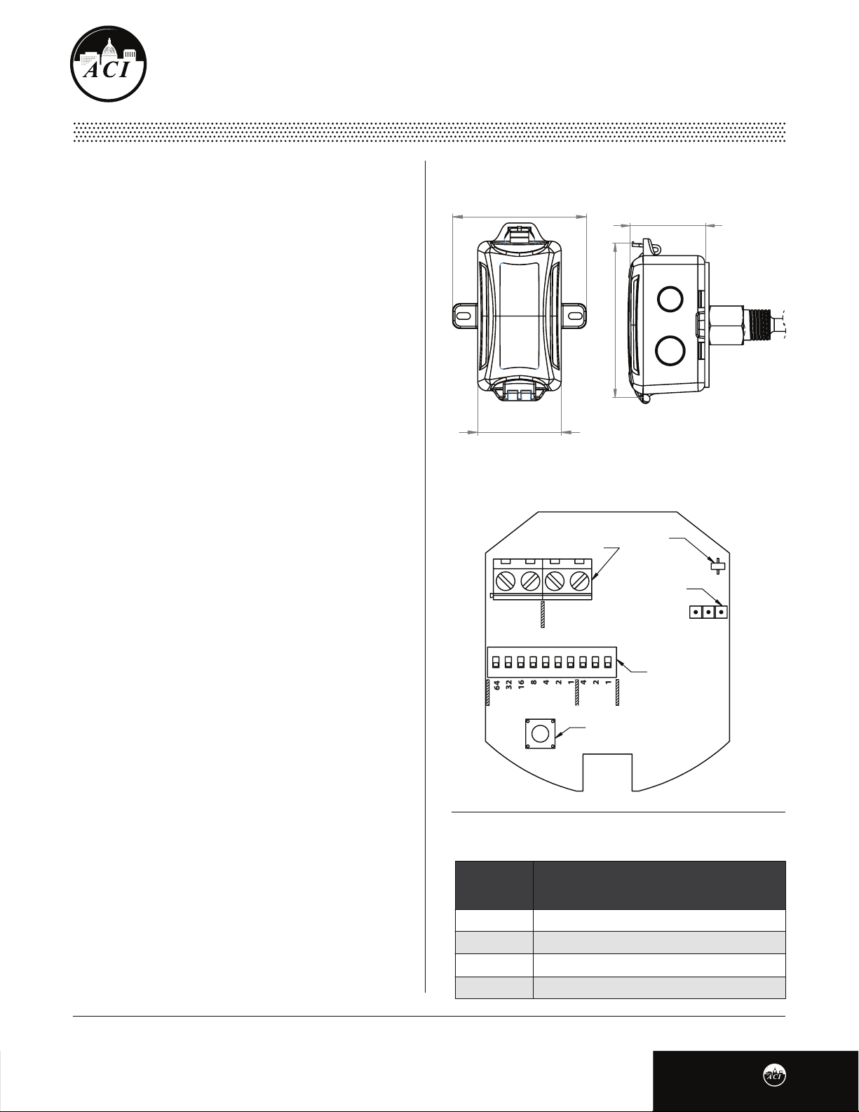
FIGURE 1: ENCLOSURE DIMENSIONS
3.60"
(91.44 mm)
4.79"
(121.55 mm)
2.25"
(57.15 mm)
2.35"
(59.80 mm)
FIGURE 2: LAYOUT
TERMINAL BLOCKS
V D-GN
POWER
D+
BACNET
LED
END OF LINE
TERMINATION
EN DIS
Avoid running communication wires next to AC line
voltage wires. These can be sources of noise that can
aect signal quality.
PRECAUTIONS
• DO NOT RUN THE WIRING IN ANY CONDUIT WITH
LINE VOLTAGE (24/120/230 VAC).
Remove power before wiring. Never connect or
•
disconnect wiring with power applied.
It is recommended you use an isolated UL-listed
•
class 2 transformer when powering the unit with
24 VAC. Failure to wire the devices with the correct
polarity when sharing transformers may result in
damage to any device powered by the shared
transformer.
23618421421
4
6
ADDRESS BAUD
RESET BUTTON
TABLE 1: WIRING CONNECTIONS
TERMINAL
BLOCKS
+V
GN
D-
D+
Page 1
CONNECTIONS
Power Supply Positive 12-36 VDC / 24 VAC
Power Supply Common or Ground
EIA-485 Data Negative
EIA-485 Data Positive
DIP SWITCH
Version 1.0
I0000805
Page 2
PRECAUTIONS
If the 24 VDC or 24VAC power is shared with devices
•
(Continued)
that have coils such as relays, solenoids, or other
inductors, each coil must have an MOV, DC/AC Transorb,
Transient Voltage Suppressor (ACI Part: 142583), or
diode placed across the coil or inductor. The cathode, or
banded side of the DC Transorb or diode, connects to
the positive side of the power supply. Without these
snubbers, coils produce very large voltage spikes when
de-energizing that can cause malfunction or
destruction of electronic circuits.
For optimal temperature readings, follow these tips:
• The sensor thermowell should be installed against the ow
of the water, where water temperature is well mixed (no
stratication).
*Reference FIGURE 4 (next page)
• Make sure the entire thermowell is immersed. If the
thermowell is longer than the pipe diameter, the
thermowell should be installed in an elbow or Tee.
• Apply thermal grease to the end of the probe before
installation into thermowell (ACI Item #102595).
• The tip of the thermowell should be located in the
middle of the pipe.
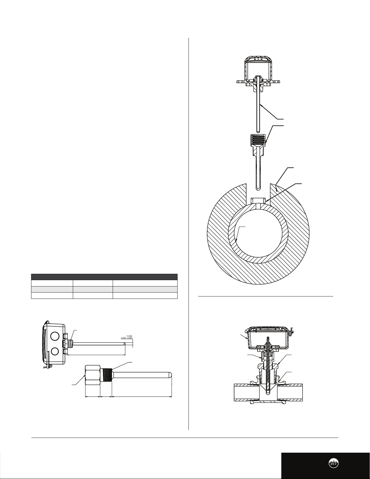
FIGURE 4: ASSEMBLY
IMMERSION SENSOR
THERMOWELL
PIPE INSULATION
THREADOLET
PIPE WALL
MOUNTING
TABLE 2: PROBE & INSERTION LENGTH
ACI PART #
A/BN1110-INW2.5-PB
A/BN1110-INW4-PB
A/BN1110-INW6-PB
IMMERSION LENGTH
2.5” (63.50 mm)
4.0“ (101.60 mm)
6.25” (158.75 mm)
PROBE LENGTH
4.31” (109.47 mm) +/- 0.13” (3.30 mm)
5.81“ (147.57 mm) +/- 0.13” (3.30 mm)
7.81” (198.37 mm) +/- 0.13” (3.30 mm)
FIGURE 3: PROBE and IMMERSION
½” NPSM
Instrument Thread
Instrument Thread
½” NPSM
(25.40 mm)
REFER TO Probe Length Table
1.00”
0.78”
(25.40 mm)
½” NPT
Instrument Thread
REFER TO Immersion
Insertion Length Table
FIGURE 5: TEE MOUNT ASSEMBLY
IMMERSION SENSOR
THERMOWELL
ADAPTER
TEE PIPE FITTING
Page 2
Version 1.0
I0000805
Page 3
THERMOWELL INSTALLATION
ACI’s standard Immersion sensors are made to install into a
½” NPT female thread. Typically a Threadolet or Tee is
installed into the pipe, but a hole can also be drilled and
tapped. The pipe/system will need to be drained, unless a
Hot Tap is being used. The recommend drill size is 23/32 in.
(18 mm). Drill the hole, and tap the hole with ½”-14NPT.
Always use proper thread sealants on tapered pipe
threads of the thermowell. Screw the thermowell into the
Threadolet, Tee, or tapped hole, using a wrench to tighten
it rmly. Rell the system and check for leaks.
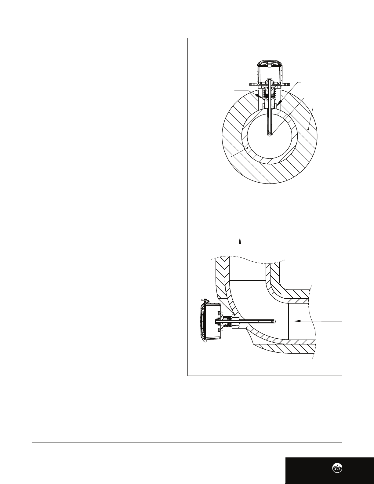
FIGURE 6: THREADOLET ASSEMBLY
THREADOLET
THERMOWELL
TIP OF THERMOWELL
IN MIDDLE OF PIPE
PIPE INSULATION
Best practice is to apply thermal grease to the end of the
probe, but not required. Insert and push the sensor probe
into the thermowell. Turn the sensor probe assembly
clockwise to tighten down completely.
Open the cover of the enclosure. Refer to the wiring
instructions (p. 3) to make necessary connections. After
wiring, attach the cover to the enclosure.
PROBE INSERTION
The “-INW” includes a standard ½” NPS process thread to
be used with a machined thermowell or previously
installed thermowell. Verify the existing thermowell
insertion length of the pipe is suitable for your selected
Immersion.
If the length of the probe is too large, the probe may be
pressed into its enclosure - up to an inch of clearance.
Note: *Fabricated (welded) thermowells (-I) are not
intended for moving water or high pressure service. Fluid
velocity and wake frequency are primary factors in well
failure. Machined thermowells (-IM) should be used in
these types of applications. Fabricated thermowells are
intended for tank, or low to no ow, applications.
PIPE WALL
FIGURE 7: ELBOW ASSEMBLY
FLOW DIRECTION
BACnet MS/TP INTERFACE
The BACnet Master-Slave/Token-Passing (MS/TP) data link protocol uses EIA-485 as a two-wire, daisy chain network. A branch is
a discrete chain of devices connected to a controller. The max number of devices per segment is (32), as per the BACnet
specications. 4000 ft (1219.2 m) is the maximum recommended length for a segment, which includes all devices from the
controller to the last device in the daisy chain. ACI’s BACnet sensors are master devices. Only master nodes are allowed to send
and receive tokens on the MSTP network.
Page 3
Version 1.0
I0000805
Page 4

BACnet MS/TP INTERFACE (Continued)
Each branch must have all devices connected with (+) connected to (+) and (-) connected to (-). If a shielded cable is used, this is
not to be connected to the devices. The shield cable should only be connected on one end to earth ground, usually at the
controller. The start and end of each branch should have a termination resistor at the device level or at the controller.
Each device must be congured for the correct baud rate and have a unique address in each branch. The baud rate for the branch
is set by the controller. This product has auto-baud for ease of network conguration but setting the baud rate using the DIP
switches is recommended.
ADDRESS SELECTION
Switches 1-7 are used to set the BACnet address. Refer to TABLE 3 for switch settings. Each device in a network branch must
have a unique address. The value of each position is printed on the board. By default, the address is (0). If the device is
powered when a change is made, the device must be power cycled or reset for changes in address to be made.
TABLE 2: ADDRESS SELECTION
ADDRESS
0
1
12
SW 1 (64)
0
0
0
SW 2 (32)
0
0
0
BAUD RATE SELECTION
Switches 8-10 are used to set the BACnet baud rate.
Refer to TABLE 4 for switch settings. Where (0) is low
and (1) is high. By default, the device is in auto-baud. If
the system’s baud rate is known, it is recommended to
set the specic baud rate to match the system. If the
device is powered when a change is made, the device
must be power cycled or reset for changes in baud rate
to be made.
EOL TERMINATION
RESISTANCE SELECTION
RS-485 requires that the last device in a chain have a
termination resistor. This is controlled using a jumper in
the EN (enabled) position marked on FIGURE 8. When
the jumper is set to EN (enabled), a 120 Ω resistance is
added in parallel to the data line. When the jumper is set
to DIS (disabled), the resistance is not added. By default,
the jumper is placed in the DIS (disabled) position.
SW 3 (16)
0
0
0
SW 4 (8)
0
0
1
SW 5 (4)
0
0
1
SW 6 (2)
0
0
0
TABLE 4: BAUD RATE SELECTION
BAUD RATE
Auto-Baud
9600
19200
38400
57600
76800
115200
SW 8
0
0
0
0
1
1
1
SW 9
0
0
1
1
0
0
1
FIGURE 8: EOL TERMINATION JUMPERS
END OF LINE
TERMINATION ENABLED
END OF LINE
TERMINATION DISABLED
EN DIS EN DIS
SW 7 (1)
0
1
0
SW 10
0
1
0
1
0
1
0
Page 4
Version 1.0
I0000805
Page 5

DEVICE CONFIGURATION THROUGH BACnet
DEVICE INSTANCE
The Device Instance, by default, is 1035000 plus the Address. For example, an Address of 21 results in a default address
of 1035021. This can be changed once the device is connected to the network, but each device instance must be unique
within the network. The device instance must be unique throughout the entire BACnet network, not just this segment.
DEVICE LOCATION
The device location is optional but is intended to allow for further denition of the device’s location. The device location can
be a character string up to 64 characters in length.
DEVICE NAME
By default, the device name is based on the type of device and the address. The
device name can be a character string up to (32) characters in length. This can be
changed once the device is connected to the network. For example: Temperature
Sensor - 034. The device name must be unique throughout the entire BACnet
network, not just this segment.
DEVICE DESCRIPTION
By default, the device name is based on the type of device and the address. The device name can be a character string up to
(32) characters in length. This can be changed once the device is connected to the network. For example: Temperature
Sensor - 034. The device name must be unique throughout the entire BACnet network, not just this segment.
LED INFORMATION
One LED indicates three statuses. Solid green shows that power is good, but no data is transmitting. A solid Amber indicates that
auto-baud is set and no data has been received to set a baud rate. Green/Amber ashing indicates data is being transmitted or
received. Solid Red LED status indicates an error state, usually loss of communication on the network. If this status remains
for (10) times the APDU timeout, the device will automatically reset. If this state remains longer than that, reset the device.
TEMPERATURE CONFIGURATION
One LED indicates three statuses. Solid green shows that power is good, but no data is transmitting. A solid Amber indicates that
auto-baud is set and no data has been received to set a baud rate. Green/Amber ashing indicates data is being transmitted or
received. Solid Red LED status indicates an error state, usually loss of communication on the network. If this status remains for (10)
times the APDU timeout, the device will automatically reset. If this state remains longer than that, reset the device.
TABLE 5: UNIT SETTING
UNITS
°F
K
°C
VALUE
64
63
62
TEMPERATURE AND RH OFFSET
This device allows for a temperature oset of +/-5 °C (9 °F) and an RH oset of +/-10%. By default, these values are set to 0,
meaning no oset is added. These are set by writing to the present value of the Temperature Calibration Oset (AV0) or RH
Calibration Oset (AV1). The value written must be within the specied range or an error will be returned. To set these back
to factory settings, write any changed values to (0).
TEST MODE
For the Sensor objects (AI0 and AI1), a test mode can be set by writing the Boolean value true to the “out-of-service”
property. Then the present-value can be set to any valid test value the user requires. This allows a user to test reactions to
specic values returned by this device.
RESET
The reset button can be used to reset the device without disconnecting power. The location of this button is shown in FIGURE 7 (p.3).
Page 5
Version 1.0
I0000805
Page 6

TABLE 6: BACnet OBJECT TABLE
OBJECT TYPE
Device
Analog
Inputs
Analog
Values
OBJECT ID
- - - - - - - - - -
AI-0
AI-1
AV-0
AV-1
OBJECT NAME
BN11x0
Temperature Sensor
RH Sensor
Temperature
Calibration Oset
RH Calibration Oset
PRODUCT SPECIFICATIONS
Supply Voltage:
Current Consumption:
Number Temperature Sensing Points:
Operating Temperature Ranges
For Board:
For Sensor:
Storage Temperature Range:
Temperature Measurement Accuracy:
Temperature Calibration Oset:
Operating Humidity Range:
RH Measurement Range:
RH Measurement Accuracy:
RH Calibration Oset:
Temperature / RH Update Rate:
Communication Protocol:
Sensor Addresses:
Supported Baud Rates:
Device Instance Number:
Connections / Wire Size:
Terminal Block Torque Rating:
Probe and Thermowell Diameter:
Probe Material
Thermowell Instrument:
Enclosure Specications:
RANGE
0-4194302
-40.0 - 302.0
0.0 - 100
-9.0 - 9.0
-10.0 -10.0
BACnet ENGINEERING UNITS
- - - - - - - - - - - - - - - - - - - - - - - - - - -
degrees-Fahrenheit (64) - default
percent-relative-humidity (29)
delta-degrees-Fahrenheit (120)
percent-relative-humidity (29)
12 to 36 VDC / 24 VAC +/- 10%, 50/60 Hz (Reverse Polarity Protected)
25 mA maximum (0.67 VA)
One
-22 to 176°F (-30 to 80°C)
-40 to 302°F (-40 to 150°C )
35 to 122°F (-40 to 85°C)
@ 77°F (25°C): +/- 1.0°F (+/- 0.5°C)
+/- 9°F (+/- 5°C) (Field Congurable)
0 to 95%
+/- 2% from 10 to 90% RH
@ 77°F (25°C): +/- 10% RH (Field Congurable)
4 seconds
BACnet MS/TP; EIA RS-485
0 to 127 (0 (Default); Field Selectable)
Auto Baud (Default), 9600, 19200, 38400, 57600, 76800, 115200 (Field Selectable)
1035000 + Address (example: Address 127 = 1035127; Field Congurable)
Screw Terminal Blocks / 16 AWG (1.31 mm2) to 22 AWG (0.33 mm2)
0.45 lbf-in (0.5 Nm) nominal
10 to 95% RH, non-condensing
0.250” (6.35mm) | 0.260” (6.60mm)
304 Stainless Steel
½” NPS (National Pipe Straight) Male Thread
“-PB” Enclosure: ABS Plastic, UL94-HB, Plenum Rated
Page 6
Version 1.0
I0000805
Page 7

W.E.E.E. DIRECTIVE
At the end of their useful life the packaging and product should be disposed of via a suitable recycling centre. Do not
dispose of with household waste. Do not burn.
BACnet is a registered trademark of ASHRAE. ASHRAE does not endorse, approve or test products for compliance with ASHRAE standards. Compliance of listed products to the requirements of ASHRAE
Standard 135 is the responsibility of BACnet International (BI). BTL is a registered trademark of BACnet International.
Page 7
Version 1.0
I0000805
 Loading...