

Page 1

Installation and Operation Instructions
READ THESE INSTRUCTIONS BEFORE YOU BEGIN INSTALLATION
PRODUCT APPLICATION
The A/TT-RSO is a temperature transmitter product family intended for room applications. Optional
features, if selected, provide useful features often desired in room applications, including setpoint and
override outputs. Both the temperature transmitter and the setpoint transmitter functions support 4-20mA,
1VDC to 5VDC, and 2VDC to 10VDC output options. The setpoint function also supports resistance output
options, with or without an offset resistance. The override function provides a normally open dry-contact
switch output for occupancy indication.
This instruction covers the following A/TT-RSO family products: A/TT-R, A/TT-RS, A/TT-RSO and A/TT-RO.
CAUTION—ELECTRICAL HAZZARD: Can cause electrical shock or equipment damage. Be sure to
make all connections with the power source turned off.
CAUTION—Do not mount product in refrigerated areas, and do not allow condensation to form on
product.
INSTALLATION INSTRUCTIONS
A/TT-RSO
Mounting:
Install the A/TT-RSO in a room location approximately 5 feet (1.5m) above the floor, preferably on an interior
wall in an area with good air circulation and average temperature. Do not mount in areas with drafts or
dead spots, in areas affected by hot or cold air ducts, or in areas with direct sunlight or other radiant heat
sources.
Remove the cover from the base; if needed turn the (2) 1/16” Allen Screws located at the bottom of the base
clockwise in order to remove the cover from the base. Pull wires through the wire access area in the base
located near the terminal blocks. Mount the base to the wall, using the (2) 6/32” x 1” screws provided.
Replace the cover and tighten down, using the (2) 1/16” Allen screws located on the bottom of the base.
Power Source:
8.5VDC to 32VDC (AC voltage is not supported).
Temperature transmitter function: 25mA maximum.
Setpoint transmitter function: 25mA maximum if current or voltage output is selected.
Notes:
1. If the A/TT-RSO is selected with both the temperature and the setpoint transmitter features, 50mA
is required from a single power source.
2. The A/TT-RSO temperature transmitter function and setpoint transmitter function can be operated
with two power sources to allow for separate 4-20mA current loops.
3. If the A/TT-RSO is selected with the resistance setpoint feature, the setpoint resistance supports a
maximum of 0.25 Watt power dissipation capability.
Wiring: (All wiring must comply with applicable local electrical codes and ordinances.)
The use of 18 to 22 AWG shielded cable is recommended for all wiring applications. Terminate the shield
at the controller-end.
A minimum of 2 and a maximum of 7 wires are required to operate the A/TT-RSO, depending on the
features selected. The A/TT-RSO has terminal blocks installed to support the selected features. Loosen the
appropriate screw terminals. Insert the wires into the terminal block, and then re-tighten the screws. Place
the cover back onto the base and turn the setscrews counter-clockwise to hold the cover.
Version : 5.0
I0000258
Page 1 of 4
Page 2
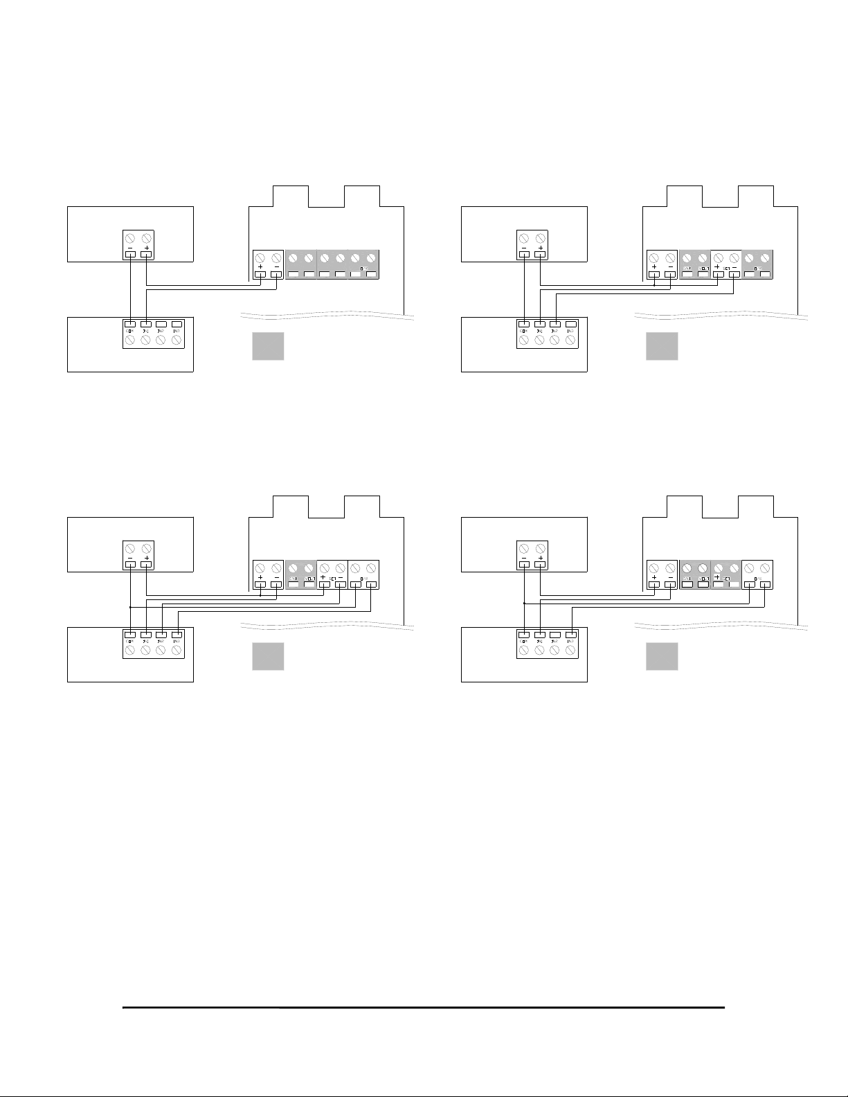
Wiring Diagrams:
Typical 2-wire 4-20mA Current Loop Transmitter Connections:
Figure 1: A/TT-R (Current Output) Figure 2: A/TT-RS (Current Output)
Temperature: 4-20mA
DC Power Source
Terminal Block(s) Terminal Block(s)
Controller
Temperature: 4-20mA
Setpoint: 4-20mA
DC Power Source
Controller
Figure 3: A/TT-RSO (Current Output) Figure 4: A/TT-RO (Current Output)
Temperature: 4-20mA
Setpoint: 4-20mA
Normally Open Dry-Contact Override
DC Power Source
Terminal Block(s) Terminal Block(s)
Temperature: 4-20mA
Normally Open Dry-Contact Override
DC Power Source
= Not Loaded= Not Loaded
Controller
= Not Loaded= Not Loaded
Controller
Version : 5.0
I0000258
Page 2 of 4
Page 3

Wiring Diagrams:
Typical Voltage Transmitter Output Connections:
Figure 5: A/TT-R (Voltage Output) Figure 6: A/TT-RS (Voltage Output)
Temperature: 1VDC to 5VDC or 2VDC to 10VDC
DC Power Source
Terminal Block(s) Terminal Block(s)
Controller
Temperature: 1VDC to 5VDC or 2VDC to 10VDC
Setpoint: 1VDC to 5VDC when R (resistor) is 249 ohms
Setpoint: 2VDC to 10VDC when R (resistor) is 499 ohms
DC Power Source
Install R at
Controller
R
Controller
Figure 7: A/TT-RSO (Voltage Output) Figure 8: A/TT-RO (Voltage Output)
Temperature: 1VDC to 5VDC or 2VDC to 10VDC
Setpoint: 1VDC to 5VDC when R (resistor) is 249 ohms
Setpoint: 2VDC to 10VDC when R (resistor) is 499 ohms
Normally Open Dry-Contact Override
DC Power Source
Terminal Block(s)
Temperature: 1VDC to 5VDC or 2VDC to 10VDC
Normally Open Dry-Contact Override
DC Power Source
= Not Loaded= Not Loaded
Terminal Block(s)
Install R at
Controller
Controller
R
= Not Loaded
Controller
OPERATION INSTRUCTIONS
General:
After mounting and wiring the A/TT-RSO family product, apply power to the system.
Temperature:
Observe the temperature signal at the end-device. If no temperature signal is observed, be sure the two
sensor shunts are installed on the A/TT-RSO circuit board (shunts located in the lower right corner).
Setpoint: (If selected)
Observe the setpoint signal at the end-device. Change the setpoint by moving the slide lever located at the
bottom of the enclosure.
Override: (If selected)
Observe the override signal at the end-device when the override pushbutton, located on the right side of the
enclosure, is pressed.
Version : 5.0
I0000258
Page 3 of 4
Page 4

PRODUCT SPECIFICATIONS
Supply voltage:
Output current:
(Current output models.)
Output voltage:
(Voltage output models.)
Calibration accuracy:
(Includes linearity.)
Temperature drift:
Voltage drift:
Warm-up drift:
Operating temperature:
Operating humidity:
Terminal voltage: 8.5VDC to 32VDC
249 ohm load resistance: 13.5VDC to 32VDC
499 ohm load resistance: 18.5VDC to 32VDC
Maximum load resistance: (Supply voltage-8.5)/0.02
Maximum terminal voltage: 32VDC
Nominal: 4mA to 20mA
Maximum: 25mA
Minimum: 3mA
Nominal: 2VDC to 10VDC
Maximum: 12.5VDC
Minimum: 1.5VDC
±0.2% of full scale
±0.04% of full scale output
±0.001% of full scale output
(Output change per volt change across terminals.)
±0.1% of full scale output
(After 10 minutes.)
32ºF to 122ºF
(0ºC to 50ºC)
0% to 90%
(Operating environment must be NON-CONDENSING.)
Version : 5.0
I0000258
Page 4 of 4
 Loading...