

Page 1
Installation and Operation Instructions
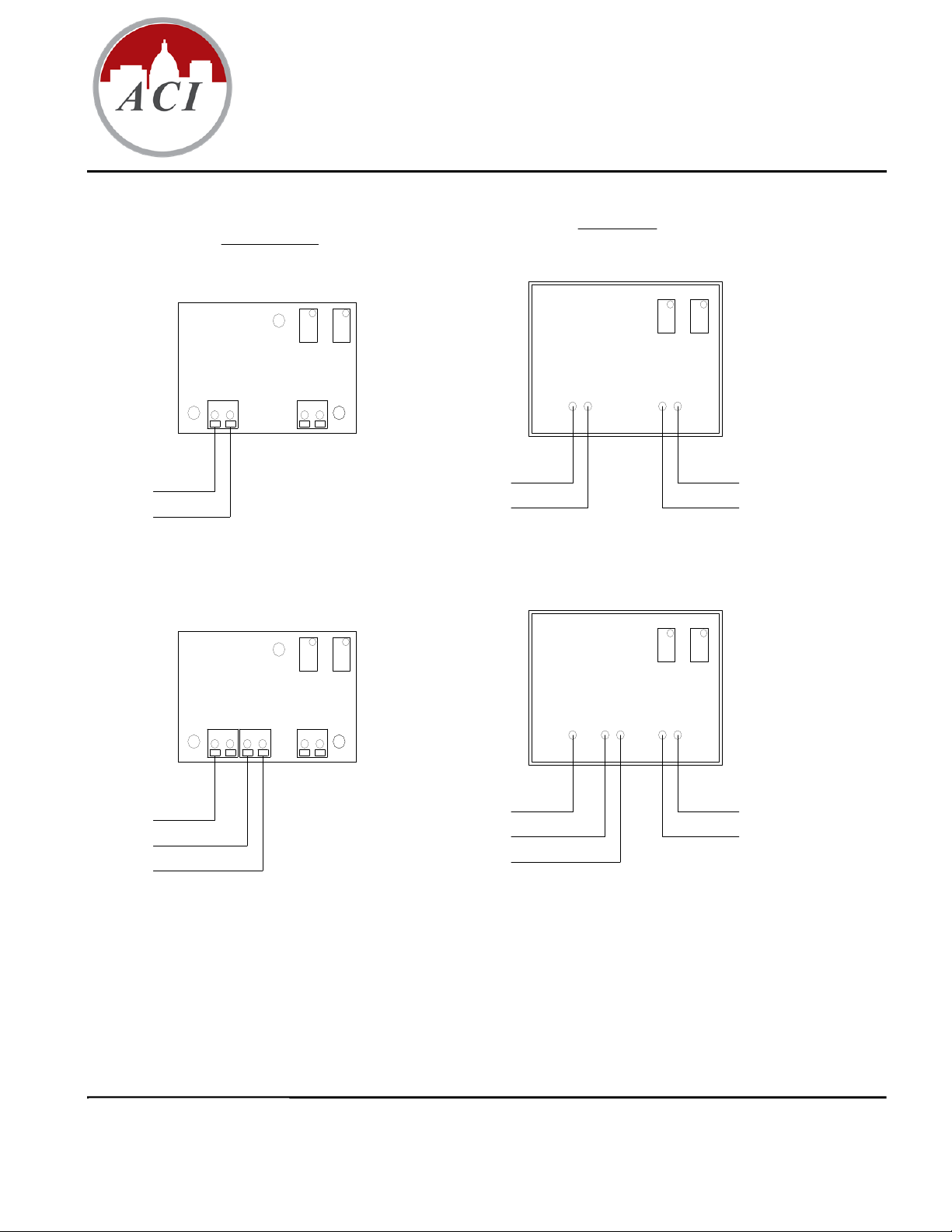
A/TT100, A/TT1K
A/TTM100, A/TTM1K
+VDC
4 to 20mA Output
READ THESE INSTRUCTIONS BEF
Standard Units
Current Output
(4 to 20 mA)
SPAN
ZERO
-+
-
+
Voltage Out put
(1 to 5, 2 to 10VDC)
RTD
+VDC (Red Wire)
4 to 20mA Output (White Wire)
SPANZERO
ORE YOU BEGIN INSTALLATION
Potted Units
Current Output
(4 to 20 mA)
SPANZERO
Voltage Out put
(1 to 5, 2 to 10VDC)
SPAN
ZERO
RTD Wires
(100 Ohm RTD Brown Wires)
(1K Ohm RTD Black Wires)
+
+VDC
GND
Voltage Out put
(1 to 5, 2 to 10VDC)
-
GND
VOUT
-
+
RTD
+VDC (Red Wire)
GND (White Wire)
RTD Wires
(100 Ohm RTD Brown Wires)
(1K Ohm RTD Black Wires)
Volt age Output (Yel low Wire)
(1 to 5, 2 to 10VDC)
The A/TT and TTM DO NOT support an AC input.
All ACI/TT and TTM temperature transmitters can be powered from either an unregulated or regulated 8.5 to 32VDC power
supply. The minimum voltage at the transmitter power terminal is 8.5V after load resistor voltage drop.
249 ohm load resistor (1-5VDC output) = 13.5V minimum supply Voltage
499 ohm load resistor (2-10VDC output) = 18.5V minimum supply Voltage
Several transmitters may be powered from the same supply as shown below.
I0000100
Page 1 of 3
Version : 2.0
Page 2

Each transmitter could draw 25mA. To determine the number of transmitters use the following formula:
N=I/25mA
where: N = number of transmitters
I = current available from power supply
25mA = maximum current draw of transmitter
e.g., If I = 1.5A then:
N = 1.5/25mA
N = 60
Therefore a 1.5A power supply will safely power up to 60 transmitters.
Power Supply
VDC
-
Gnd In1 In2 In3
Controller
+
All A/TT and TTM temperature transmitters are reverse polarity protected.
Temp.Transmitter #1 Temp.Transmitter #NTemp.Transmitter #2
+ - + - + -
= Connections
In1 = Controller Input #1
In2 = Controller Input #2
In3 = Controller Input #3
Room Temperature Transmitters
This unit is suitable for either drywall or junction box mounting. First, remove the cover of the housing and mount the base of
the Room unit to the wall, using the (2) 6/32” x 1” screws that are provided. Once the base is mounted to the wall, make all of
the proper connections and then place the cover back onto the unit. Now tighten the cover down, using the (2) Allen screws
located in the bottom of the housing. The Room transmitter is provided with a two pole terminal block for power and a two
pole terminal block for the RTD, which allows for easy wiring of the unit.
Duct & Duct Averaging Temperature Transmitters
Duct Temperature Sensors - Drill a 3/8” hole in the duct and insert the probe through the hole until the foam pad is tight to the
duct. Now insert (2) screws through the mounting holes in the flange and tighten until the unit is held firmly to the duct.
Duct Averaging Sensors – Drill a 3/8” hole in the duct and insert the averaging element through the hole until the foam pad is
tight to the duct. Now insert (2) screws through the mounting holes in the flange and tighten until the unit is held firmly to the
duct. The sensor should then be strung in a criss-cross pattern throughout the duct (see Figure #2) using the mounting clips
provided, in a pattern that covers the greatest surface area of the duct, to insure that there is no stratification. When bending the
copper tubing, be careful that you use a gradual bend and that you DO NOT kink the copper tubing.
I0000100
Page 2 of 3
Version : 2.0
Page 3

Immersion Temperature Transmitters
m
f
t
The ACI Immersion type transmitters are provided with a 2.5”, 4” or 8” 304 series stainless steel thermowell. The thermowell
has a 1/2” external or process NPT threads and 1/2” internal or instrument NPT threads. All of the ACI thermowells will
accept a probe diameter of 0.250”.
Strap-On Temperature Transmitters
The ACI Strap-On transmitters are provided in a junction box with an adjustable 2” to 5” pipe clamp. The unit should be
mounted on the bottom side of the pipe to ensure good temperature transfer. In hot water applications (over 150
recommended that the transmitter be remote located so as not to exceed the operating temperature of the transmitter. Extra
straps may be ordered for larger diameter pipes.
o
F) it is
Outside Air Temperature Transmitters
The ACI Outside Air transmitters are provided in two parts including a weatherproof enclosure and a 2” X 4” junction box.
The sensors will be mounted in the weatherproof enclosure and mounting hardware is provided. The transmitter will be
provided in the 1 gang junction box and should be mounted on an inside wall so as not to exceed the operating temperature
limits of the transmitter. This sensor should be mounted on either the North side of the building or anywhere out of direct
sunlight with the sensor probe pointed downward. Weatherproof Aluminum Bell Boxes and NEMA 4X Polycarbonate
enclosures are available upon request.
Stainless Plate Temperature Transmitters
The ACI Stainless Plate temperature transmitters are mounted on the back of a 2” x 4” stainless plate. The sensor is covered
with a 1/8” foam insulation, which allows the sensor to sense the actual room temperature and ignore any heat produced by the
transmitter or drafts from within the wall. All mounting screws are provided.
Troubleshooting
No Reading No power to board - check voltage at power terminal - should be between
+8.5 and 32 VDC.
Reading too Low RTD wires shorted - check with ohmmeter - should be close to either
100 or 1000 Improper range of transmitter (too low) - check
cur rent - should be between 4 and 20mA.
Reading too High RTD opened - check with ohmmeter - should be close to either 100 or
1000 Improper range of transmitter (too high) - check current -
should be between 4 and 20mA.
RF Interference Input power must be clean. Use twisted wires or shielded cable. RF
resistant power supply. Use a shielded cable to connect the sensor -
co nnect the shield to ground. Encase the board in a RF shielded
enclosure.
OHMS
Disconnect RTD before
testing sensor resistance
Black
Lead
Oh
Meter
Red
Lead
~ 100 Ohm or
~ 1000 Ohm
Measure across the + and – o
RTD
+1 to 5 VDC / +2 to 10 VDC
VOLTS
the Power Wires
+ -
Red
Lead
Vol
Meter
Output
Black
Lead
Power Supply /
Controller Common
Power
Supply
CURRENT
Disconnect (-) and place
meter in Series
Black
Lead
Red
Lead
Current
Meter
+4 to 20 mA
Output
To Controller
Input or Power
Supply Common
I0000100
Page 3 of 3
Version : 2.0
 Loading...