

ACI-Automation Components A/CTA-5, A/CTA-50, A/CTA-250, A/CTA-5-VFD, A/CTA-50-VFD Instruction Sheet
...Page 1
Installation and Operation Instructions
ACI
A/CTA-5
e ,
3X
A/CTA-5
Middleton, WI
ACI
3X
C
3JHX
US
LISTED
IND.CONT.EQ.
600:5 Ratio 5A C.T.
Example: For currents up to 600 Amps
(and not below 70 Amps, where
Current Transformer (C.T.)
secondary falls down to 1 Amp)
use a 600:5 ratio C.T. as shown:
Wire
Nut
Insulated
Conductor
!
Part # A/CTA-5, A/CTA-50, A/CTA-250,
Please Read Instructions Carefully Before Installation!
Safety
This product is not intended to be used for Life or Safety applications.
This product is not intended for use in any hazardous or classified locations.
Disconnect and lock out all power sources before installation as severe injury or death may result from electrical
shock due to contact with high voltage wires.
Installation
Make sure that all installations are in compliance with all national and local electrical codes. Only qualified individuals that are
familiar with codes, standards, and proper safety procedures for high-voltage installations should attempt installation. The
current sensor is a 2-wire, 4 to 20 mA Loop Powered device that requires a regulated +12 to 30VDC external power source.
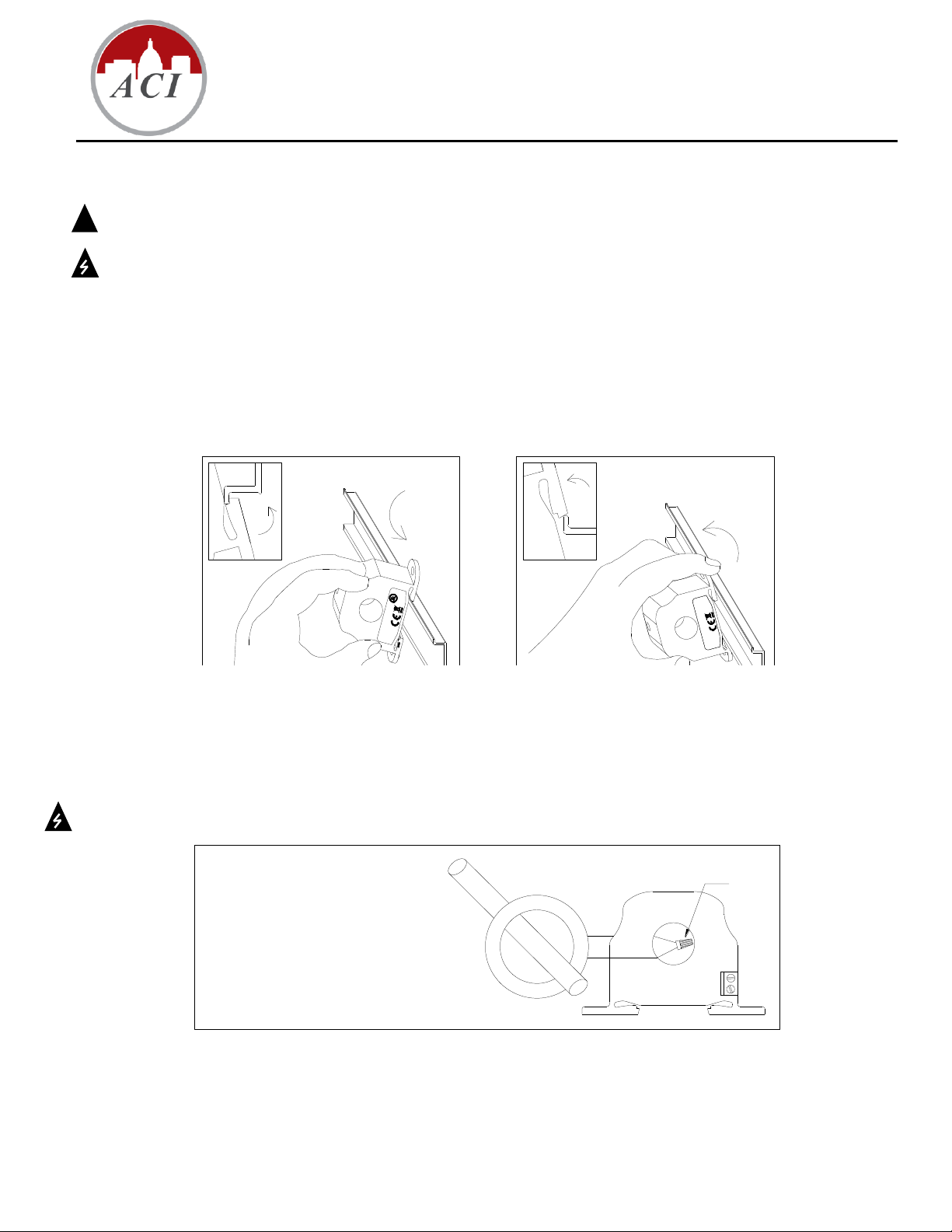
The A/CTA Series Analog Current Sensors should be used on Insulated Conductors Only! The current sensors may be mounted
in any position using the (2) #8 x ¾” Tek screws and the mounting holes in the base or snapped directly on to the 35mm DIN rail
(See Figures 1 & 2 below). Leave a minimum distance of 1” (3 cm) between the current sensor and any other magnetic devices
such as contactors and transformers.
A/CTA-5-VFD, A/CTA-50-VFD, A/CTA-250-VFD
Figure 1: Sensor Placed on Rail Figure 2: Sensor Removed From Rail
For applications in which the normal operating current is greater than 250 Amps or for conductor diameters larger than 0.750”
(1.90 cm) in diameter, an external 5 Amp Current Transformer must be used in conjunction with an A/CTA -5 or A/CTA-5-VFD as
shown in Figure 3 below.
Remember that the secondary of the 5A CT must be shorted together before the power may be turned on from the device.
Figure 3: Current Transformer
Page 1 of 3 I0000139
Version : 2.0
Page 2
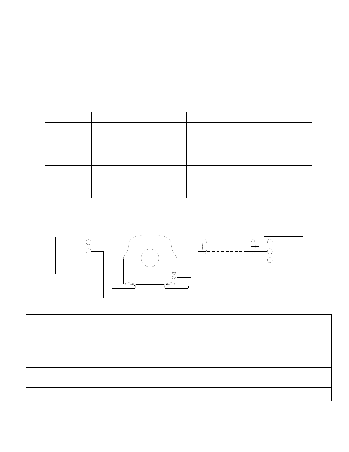
Wiring
Supply
Power
+12 to 30 VDC
4 to 20 mA
+
_
DC
_
+
Signal Input
+
Building Automation
GND (Shield)
System
Common
Problem
Solution
No reading
- Confirm that you have +12 to 30VDC in series with the current sensor output
terminals and the analog input of the control panel.
- Check the polarity of the circuit.
- Verify that the terminals are screwed down, wires are firmly in place.
- Disconnect the input to the control panel and then insert a current meter
(mA range) in series with the current sensor output to verify that the circuit is
working properly.
Erratic readings
- Verify that the wires are terminated properly.
- Check that the +12 to 30VDC input is clean. In areas of high RF interference,
shielded cable may be necessary to stabilize signal.
Inaccurate readings
- If you suspect that the current sensor is not reading within the accuracy specifications,
please contact the factory for assistance.
ACI Model #
Range
Jumper *
Max. Sensing
Current Voltage
Max. Continuous
Current.
Max. Current for
6 seconds
CE Compliance
A/CTA-5
0-5 Amps
None
600 VAC
100 Amps
125 Amps
Yes
A/CTA-50
0-10 Amps
0-20 Amps
0-50 Amps
Low
Middle
High
600 VAC
100 Amps
150 Amps
200 Amps
125 Amps
225 Amps
300 Amps
Yes
A/CTA-250
0-100 Amps
0-200 Amps
0-250 Amps
Low
Middle
High
600 VAC
200 Amps
360 Amps
400 Amps
250 Amps
450 Amps
500 Amps
Yes
A/CTA-5-VFD **
0-5 Amps
None
600 VAC
60 Amps
100 Amps
No
A/CTA-50-VFD **
0-10 Amps
0-20 Amps
0-50 Amps
Low
Middle
High
600 VAC
60 Amps
100 Amps
160 Amps
80 Amps
200 Amps
300 Amps
No
A/CTA-250-VFD **
0-100 Amps
0-200 Amps
0-250 Amps
Low
Middle
High
600 VAC
160 Amps
320 Amps
400 Amps
200 Amps
400 Amps
500 Amps
No
ACI recommends the use of a 2 conductor 16 to 22 AWG shielded cable, copper wire only for all 4 to 20mA current sensor
installations. A maximum wire length of less than 30 meters (98.4 feet) should be used between the A/CTA series current sensors
and the Building Management System or controller. Note: When using a shielded cable, be sure to connect only (1) end of the
shield to ground at the controller. Connecting both ends of the shield to ground may cause a ground loop. When removing the
shield from the sensor end, make sure to properly trim the shield so as to prevent any chance of shorting. The current sensors
terminals are polarity sensitive and represent a linear and proportional 4 to 20mA output signal. The current sensors are available
in either an Average or True RMS output version. The recommended torque to be used on the terminal block connections is 0.67
Nm or 5.93 in-lbs. The aperture (hole) size of the current sensor is 0.75” (1.90 cm) and will accept a maximum cable diameter of
350 MCM’s.
Operating Specifications
*Note: All current sensors are shipped from the factory with the jumper set in the high range.
** Note: All -VFD models have True RMS outputs and should be used with Variable Frequency Drives.
Troubleshooting
Wiring Example
Version : 2.0
Page 2 of 3 I0000139
Page 3
LISTED
C US
IND.CONT.EQ.
3JHX
Current Conversion Formulas
To convert the current sensor output signal to a current reading.
4-20mA output to Current reading (4mA = 0 Amps and 20mA = 250 Amps for A/CTA-250)
Example: 12mA current sensor output signal
Total Span = 250 Amps
Multiplier = 20mA-4mA/Total Span = 0.064
(12mA-4mA)/0.064= 125 Amps
WEEE Directive
At the end of their useful life the packaging and product should be disposed of via a suitable recycling centre. Do not dispose of
with household waste. Do not burn.
Page 3 of 3 I0000139
Version : 2.0
 Loading...