

Page 1
A
utomation
ACI/AFS-222, ACI/AFS-262
C
omponents
I
nc.
PLEASE READ THE FOLLOWING INFORMATION BEFORE INSTALLATION
n MOUNTING
Select a location which is free from vibration . The ACI/AFS Series pressure switches must be mounted in any
vertical plane in order to be able to reach the lowest specified operating setpoint. Avoid mounting with the sample
line connections in the “up” position. Surface mount via the (2) 3/16” diameter holes in the integral mounting
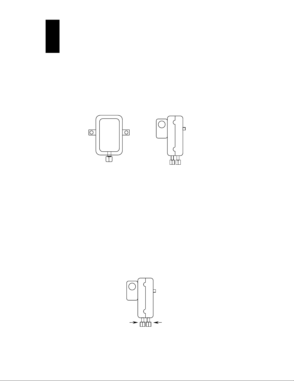
bracket. The mounting holes are 3 7/8” apart. See Figure #1
Figure # 1
Installation and Operation Instructions
Important!
n AIR SAMPLING CONNECTION
The ACI/AFS is designed to accept firm-wall sample lines of 1/4” O.D. tubing by means of a ferrule and nut
compression fitting. An optional 1/4 ad ” aptor, suitable for slip-on flexible tubing is available. For sample lines
of up to 10 feet, 1/4” O.D. tubing is acceptable and for lines up to 20 feet, use 1/4” I.D. tubing. For lines from
20-60 feet, use a 1/2” I.D. tubing. A 1/4” O.D. Adaptor, suitable for slip-on flexible tubing is available (Part#
18311). Locate the sampling probe a minimum of 1.5 duct diameters downstream from the air source. Install the
sampling probe as close to the center of the airstream as possible. Refer to figure #2 to identify the high pressure
inlet (A) and the low pressure inlet (B). Select one of the 5 application options listed below, and connect the
sample line as recommended.
Positive Pressure Only: Connect the sample line to inlet A; inlet B remains open to the atmosphere.
Negative Pressure Only: Connect the sample line to inlet B; inlet A remains open to the atmosphere.
Two Negative Samples: Connect the higher negative sample to inlet B; connect the higher negative
sample to inlet A.
Two Positive Samples: Connect the higher positive sample to inlet A; connect the lower positive
sample to inlet B.
One Positive and One Negative Sample: Connect the positive sample to inlet A; connect the negative
sample to inlet B.
Figure #2
Inlet A:
Negative Only
Higher Negative
Lower Positive
Inlet A:
Positive Only
Lower Negative
Higher Positive
II- 57
Page 2
N
N
N
N
n
ELECTRICAL CONNECTIONS
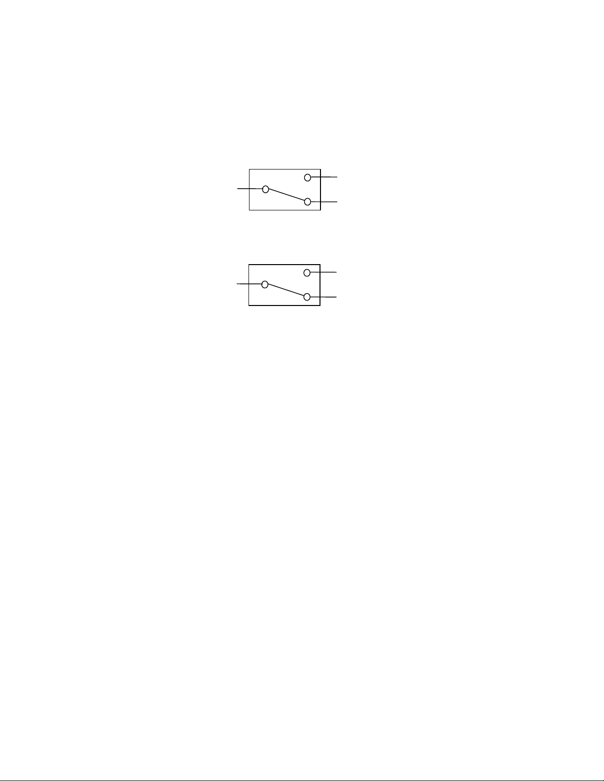
Before pressure is applied to the diaphragm, the switch contacts will be in the Normally Closed (NC) position.
The snap switch has screw top terminals with cup washers. Wire alarm and control applications as shown in
Figure #4.
Figure #4
To prove excessive air flow or pressure:
C
/O
/C
Alarm
Control
To prove insufficient air flow or pressure:
C
/O
/C
Control
Alarm
n FIELD ADJUSTMENT
The adjustment range of the ACI/AFS-222 Air Switch is 0.05 to 12.0” w.c. +/- 0.02” w.c. Whereas the
adjustment range of the ACI/AFS-262 Air Switch is 0.05 to 2.0” w.c. +/- 0.02” w.c.
To adjust the Setpoint: Turn the adjusting screw counterclock-wise until the motion has stopped. Next, turn
the adjusting screw 4 complete turns in a clock-wise direction to engage the spring.
From this point, the next 10 turns will be used for the actual calibration. Each full turn
represents approximately 0.2” w.c..
Please Note: To properly calibrate an Air Switch, a digital manometer, or other measuring device should be used
to confirm the actual setpoint.
II-58
 Loading...