

Page 1
NOTE
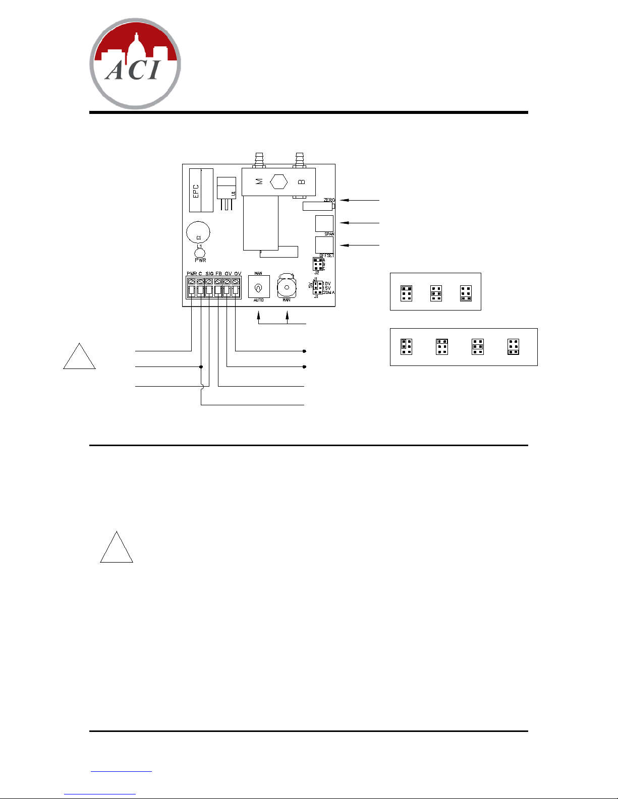
#1
Power
(+)
(-)
Ana lo g In pu t Sign a l
(+)
(-)
Branch Pres sure
Feedback Signa l
Override Feedback
(Dr y Co nt ac t)
Manual Override Pot
and Manual/Auto
Switch
Offse t Pot - Set for mini mum desired
pressure with minimum input signal
Span Pot - Se t fo r maximum desired
pressure with maximum input signal
Zero Pot is Factory Set - Do not adjust
SEE
NOTE
#1
(+)
A
B
C
J2
0-10 psi
A
B
C
J2
0-15 psi
A
B
C
J2
0-20 psi
10V
15V
J1
5V
20mA
0-5 VDC
10V
15V
J1
5V
20mA
0-10 VDC
10V
15V
J1
5V
20mA
0-15 VDC
10V
15V
J1
5V
20mA
0-20mA
Pressure Output Range Selector
Signal In put Range Sele ctor
Installation and Operat ion Instructions
EPC
Analog Current or Voltage Input to Modulated Pressure Output
With Bleed Orifice
INSTALLATION
READ THESE INSTRUCTIONS BEFORE YOU BEGIN INST ALLATION.
Ground yourself before touching board. Some components are static sensitive.
Mounting:
Circuit board may be mounted in any position. If circuit board slides out of snap track, a non-conductive
“stop” may be required. Use only fingers to remove board from snap track. Slide out of snap track or push
against side of snap track and lift that side of the circuit board to remove. Do not flex board or use tools.
POWER CONNECTIONS – THIS PRODUCT ACCEPTS 24 VDC OR 24 VAC POWER.
Be sure to follow all local electrical codes. Refer to wiring diagram for connection information.
Be sure to make all connections with the power off.
1.) DC Power – Refer to wiring diagram for connection information.
If the 24 VDC power is shared with devices that have coils such as relays,
solenoids, or other inductors, each coil must have an MOV, DC Transorb, or diode
placed across the coil or inductor. The cathode, or banded side of the DC Transorb
or diode, connects to the positive side of the power supply.
2.) AC Power – Refer to wiring diagram for connection information.
Check the wiring configuration of any other loads that may be connected to this
transformer. If required by BAS or controller specification, the 24 VAC neutral can
be
earth grounded at the transformer. Analog input, digital input, and analog output
circuits should not be earth
this transformer must use the same common. If you are not sure of other field
device configuration, use separate transformers for isolation.
If the 24 VAC power is share with devices that have coils such as relays, solenoids,
or other inductors, each coil must have an MOV, AC Transorb, or other spike
snubbing device across each of the shared coils. Without these snubbers, coils
produce very large voltage spikes when de-energizing that can cause malfunction or
AUTOMATION COMPONENTS, INC Version : 2.0
2305 Pleasant View Road Page 1 of 2 I0000479
Middleton, Wisconsin 53562 (888) 967-5224
www.workaci.com
grounded at two points. Any field device connected to
Page 2

d est ruction of electr onic circuits. Refer to wiring diagram for conne ctio n infor m atio n.
3.) You should measure the actual voltage output of the secondary. If the output is not
fully loaded you may read a higher voltage than the circuit board can handle.
ADJUSTMENT OF GAUGES. If installation requires adjustment of the gauge for proper reading of the face,
turn the gauge no more than ½ turn in either direction. O-rings in the bottom of the gauge port will allow this
without leakage.
Warranty does not include malfunction due to clog ged valv e. M ain air port on EPC is filtered with the
supplied 80 – 100 micron integral-in-barb filter (Part # PN004). Periodically check the filter for contamination
and flow reduction. Replace if needed (Part # PN004).
The surface between the manifold and pressure transducer is a pressure seal. Minimize stress between the
circuit board and the manifold by holding the manifold in one hand while installing pneumatic tubing onto the
fittings, and use care when removing tubing to avoid damaging fittings or moving manifold
.
The bleed orifice can be unscrewed with a ¼” hex driver for cleaning or inspection. Do not lose the sealing
gasket or insert anything into the precision bleed orifice. Clean by swabbing with a degreaser and blowing
clean air through the orifice from the opposite direction.
This unit requires at least two cubic inches (minimum) of branch air line capacity (approx. 15 feet of ¼” O.D.
polyethylene tubing) to operate without oscillation. Main air must be minimum of 2 psig above highest
desired branch output pressure. Do not power without main air provided.
CHECKOUT
With power off, select one of the four input signal combinations by moving the jumper shunt J1 identified as
“Input Signal Range Selector”. Select a preset pressure output range by moving jumper shunt J2 identified
as “Pressure Output Range Selector”, or set custom range as described below.
SETTING CUSTOM OUTPUT PRESSURE RANGE. Verify the MAN/AUTO switch is in the AUTO position.
In AUTO, the manual override pot is inactive, the override contacts are open, and the analog input signal is
supplying the set-point. The offset pot may be adjusted to any desired offset between 0 and 14 psig. When
in the MANUAL position, the override contacts are closed, the offset pot is inactive and the manual override
pot is supplying the set point (the analog input signal is locked out). Supply power and the LED power
indicator will light, but only measurement will verify proper voltage.
1. Setting the minimum pressure. Make sure the signal connections are made and input is at
minimum. Place the manual override switch to the AUTO position. Adjust the OFFSET pot to the
desired pressure output, or until the actuator just starts to move. The adjustment range of the
OFFSET pot is 0 to 9 psig (62.05 kPa), 0 to 14 psig (96.53 kPa), or 0 to 19 psig (131 kPa)
depending on the range selected. Zero pot is factory set – DO NOT ADJUST.
2. Setting the maximum pressure. Now place the manual override switch to the MANUAL position.
Turn the MANUAL pot to produce the maximum branch line pressure available. Turn the SPAN pot
for the maximum desired output pressure, or until the actuator just stops. Be sure the MAIN air
pressure is at least 2 psig greater than the desired maximum branch output pressure.
3. Repeat. Because the OFFSET and SPAN pots are slightly interactive, steps 1 and 2 must be
repeated until the desired minimum and maximum pressures are repeatable. Since the MANUAL
pot is set for maximum pressure, it is only required that you switch the manual override switch back
and forth from MANUAL to AUTO when repeating steps 1 and 2. Calibration is usually
accomplished in less than 3 iterations. Apply minimum and maximum input signals and measure
response. Response between the minimum and maximum values will be linear, therefore soft w ar e
algorithms are easy to derive.
The feedback signal range on all selections is 0 to 5 VDC and is proportional to the output pr es sure rang e
selected. The output and feedback signal will continue to vary proportionally if the input signal is increased
beyond its upper limit (if there is enough main air available).
The EPC is a constant bleed interface and utilizes a precision bleed orifice to maintain a measured flow of
air across the valve. The branch exhaust response time is determined by the combined ex haus t air flow as
well as pressure differentials. If power to the EPC is lost, it will continue to bleed through the orifice until
branch pressure is 0 psig. To use the manual override, place the AUTO/MAN switch in the Man position.
The potentiometer is now operable, and by turning the knob you may increase or decrease the pneumatic
output. EU Commission Directive 2002/95/EC (RoHS) Compliant
Power Supply Voltage: Air Supply:
24 VDC (+10%/-5%) Maximum 25 psig (172.38 kPa), minimum 18 psig (124.11 kPA)
24 VAC (± 1 0%) 50/60 Hz at terminals Main air supply, 0–10 psig (68.95 kPa), 0-15 psig (103.43 kPa), and
Supply Current: 0-20 psig (137.9 kPa) jumper selectable output pressure ranges.
180 mA max. Air Flow, @ 20 psig (137.9 kPa) main/15 psig (103.43kPa)
Feedback Signal Output: Exhaust Rate: 41 scim
Factory Calibrated 0-5 VDC = range selected Accuracy: 1% full scale at room temperature,
Input Signal Ranges: 0-5 VDC @ Infinite Ohms 2% full scale at 32 to 120°F (0 to 48.8°C)
0-10 VDC @ Infinite Ohms Override Contact Rating: 24 VAC or 24 VDC, 1A maximum
0-15 VDC @ Infinite Ohms
0-20mA @ 250 Ohms
AUTOMATION COMPONENTS, INC Version : 2.0
2305 Pleasant View Road Page 2 of 2 I0000479
Middleton, Wisconsin 53562 (888) 967-5224
www.workaci.com
 Loading...