

Page 1

DUCT SERIES
Installation & Operation Instructions
Phone: 1-888-967-5224
Website: workaci.com
PRECAUTIONS
• DO NOT RUN THE WIRING IN ANY CONDUIT
WITH LINE VOLTAGE (24/120/230 VAC).
GENERAL INFORMATION
The Duct sensor is a single point temperature
sensor that is designed for use with electronic
controllers in commercial heating and cooling
building management systems. It is available
with multiple thermistor or RTD options.
For optimal temperature readings, follow these
tips:
• Duct probe should be placed (3) to (4) duct segments
down from any bend or obstructions and away from
90° bends.
• Mount the sensor on the top or sides of duct work;
mounting on the bottom risks damage due to
moisture.
• The sensor should be mounted in the middle of the
duct where air circulation is well mixed (no
stratication), and not blocked by obstructions.
Stratication and obstructions can cause sensing
errors. An example is downstream from a heating or
cooling coil.
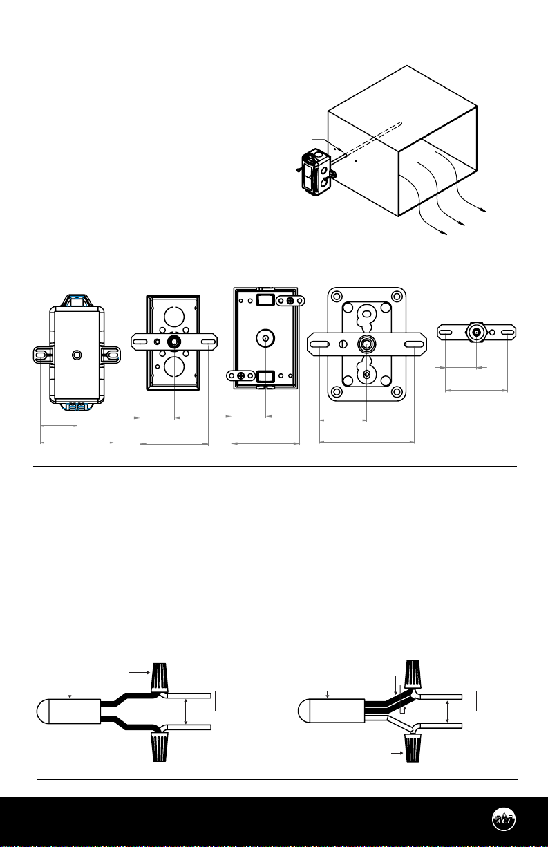
FIGURE 1: ENCLOSURE
DIMENSIONS
4.79"
(121.55 mm)
(106.68 mm)
2.35"
(59.80 mm)
(45.18 mm)
2.34"
(59.38 mm)
1.78"
PLASTIC BOX (-PB)
3.60"
(91.44 mm)
2.25"
(57.15 mm)
GALVANIZED ENCLOSURE (-GD)
3.88"
(98.60 mm)
2.41"
(61.21 mm)
4.20"
BELL BOX (-BB)
2.95"
(75.00 mm)
MOUNTING INSTRUCTIONS
Drill a 3/8” hole in the duct and insert the probe through
the hole until the foam pad is tight to the duct. Drill pilot
holes for the (2) mounting screws. Use the enclosure
ange as a guide, or use the dimensions listed below to
measure out.
WITHOUT BOX (-DO)
0.61"
3.88"
(98.60 mm)
(24.89 mm)
Automation Components, Inc.
2305 Pleasant View Road | Middleton, WI 53562
Phone: 1-888-967-5224 | Website: workaci.com
0.98"
(15.49 mm)
NEMA -4X (-4X)
Page 1
3.88"
(98.60 mm)
2.55"
(64.77 mm)
4.72"
(119.83 mm)
3.70"
(93.980 mm)
2.19"
(55.69 mm)
Version: 2.0
I0000810
Page 2
MOUNTING (Continued)
FIGURE 2: DUCT MOUNTING
Now fasten and insert (2) screws #8 x 3/4" TEK
(provided and recommended) through the
mounting holes in the ange and tighten until
the unit is held rmly to the duct. Make sure the
foam pad is tight to the duct to eliminate any
0.375"
(9.525 mm)
possible air leaks. Refer to the Wiring Instruc-
tions (p. 2-3) to make necessary connections.
Note: All enclosures have the foam pad attached.
For the “DO” (no enclosure), the foam pad is
included, but not installed. The foam pad must be
installed prior to mounting.
FIGURE 3: MOUNTING FOR DIFFERENT CONFIGURATIONS
1.54"
1.51"
(38.25 mm)
(76.51 mm)
3.01"
(39.12 mm)
(78.23 mm)
3.08"
-PB -GD -BB -4X -DO
1.59"
(40.39 mm)
(80.77 mm)
3.18"
1.54"
(39.12 mm)
3.08"
(78.23 mm)
1.54"
(39.12 mm)
(78.23 mm)
3.08"
WIRING INSTRUCTIONS
Open the cover of the enclosure. ACI recommends 16 to 26 AWG twisted pair wires or shielded cable for all
sensors. Signal wiring must be run separate from low and high voltage wires (24/120/230VAC). All ACI thermistors and RTD temperature sensors are both non-polarity and non-position sensitive. All thermistor type units
are supplied with (2) ying lead wires, and all RTD’s are supplied with (2) or (3) ying lead wires – see FIGURE
4 (below). The number of wires needed depends on the application.
FIGURE 4: TEMPERATURE WIRING
3-WIRE RTD WIRING2-WIRE THERMISTOR or RTD WIRING
THERMISTOR OR
RTD 2WIRE
Automation Components, Inc.
2305 Pleasant View Road | Middleton, WI 53562
Phone: 1-888-967-5224 | Website: workaci.com
WIRE NUT
WIRING FROM CONTROLLER
ANALOG INPUT
Page 2
RTD 3WIRE
SAME COLOR WIRES
WIRE NUT
WIRING FROM CONTROLLER
ANALOG INPUT
Version: 2.0
I0000810
Page 3

WIRING INSTRUCTIONS (Continued)
Connect thermistor/RTD wire leads to controller analog input wires using wire nuts, terminal blocks, or
crimp style connectors. All wiring must comply with all local and National Electric Codes. After wiring,
attach the cover to the enclosure.
Note: When using a shielded cable, be sure to connect only (1) end of the shield to ground at the
controller. Connecting both ends of the shield to ground may cause a ground loop. When
removing the shield from the sensor end, make sure to properly trim the shield to prevent any
chance of shorting.
Note: If the controller requires a (2) wire input for a RTD, connect the (2) common wires (same
color) together. If the controller requires (3) wires, use (3) individual wires.
TROUBLESHOOTING
PROBLEM
Sensor reading is incorrect
Sensor reads infinity/very high resistance
Sensor reads low resistance
Erratic readings
SOLUTION(S)
• Verify sensor wiring to controller is not damaged and has continuity.
• Verify sensor or wires are not shorted together.
• Verify controller is setup for correct sensor curve.
• Disconnect wires from sensor terminal block, tighten terminal block
screws down, and take a resistance (ohm) reading with a multimeter.
• Compare the resistance reading to the Temperature Vs Resistance
Curves online: http://www.workaci.com/content/thermistor-curves-0
• Verify proper mounting location to conrm no external factors are
aecting reading.
• Sensor or wires are open.
• Sensor or wires are shorted together.
• Condensation on PCB board
• Bad wire connections.
WARRANTY
The ACI Duct Series temperature sensors are covered by ACI’s Five (5) Year Limited Warranty, which is located in
the front of ACI’S SENSORS & TRANSMITTERS CATALOG or can be found on ACI’s website: www.workaci.com.
W.E.E.E. DIRECTIVE
At the end of their useful life the packaging and product should be disposed of via a suitable recycling
centre. Do not dispose of with household waste. Do not burn.
Page 3
Automation Components, Inc.
2305 Pleasant View Road | Middleton, WI 53562
Phone: 1-888-967-5224 | Website: workaci.com
Version: 2.0
I0000810
Page 4

PRODUCT SPECIFICATIONS
SENSOR NON-SPECIFIC INFORMATION
Number Sensing Points:
Storage Temperature Range:
Operating Humidity Range:
Probe Material | Diameter:
Wire Size
Enclosure Specifications:
(Temperature, Material,
Flammability, NEMA/IP Ratings)
THERMISTOR
THERMISTOR
Sensor Output @ 25 °C (77 °F):
(Lead Wire Colors)
*Does not include CL2P
Accuracy @ 0-70 °C (32 - 158 °F):
PLATINUM
Sensor Output @ 0 °C (32 °F):
Accuracy:
BALCO
Sensor Output @ 21.1 °C (70 °F):
(Lead Wire Colors)
Accuracy:
NICKEL
Sensor Output @ 21.1 °C (70 °F):
(Lead Wire Colors)
Accuracy:
One
-40 to 80 °C (-40 to 185 °F)
10 to 95% RH, non-condensing
304 Stainless Steel | 0.250” (6.35 mm)
22 AWG (0.65 mm)
“-GD” Enclosure: Galvanized Steel, -40 to 115 °C (-40 to 239 °F), NEMA 1 (IP10)
“-PB” Enclosure: ABS Plastic, UL94-HB, -30 to 90 °C (-22 to 194 °F), Plenum Rated
“-BB” Enclosure: Aluminum, -40 to 115 °C (-40 to 239 °F), NEMA 3R (IP 14)
“-4X” Enclosure: Polystyrene Plastic, UL94-V2, -40 to 70°C (-40 to 158°F), NEMA 4X (IP 66)
“-DO” No Enclosure: Polyamide 66 (High Performance Nylon), -40 to 115 °C (-40 to
239 °F), UL94-HB
A/1.8K: 1.8 KΩ nominal (Red/Yellow)
A/3K: 3 KΩ nominal (White/Brown)
A/AN (Type III): 10 KΩ nominal (White/White)
A/AN-BC: 5.238 KΩ nominal (White/Yellow)
A/CP (Type II): 10 KΩ nominal (White/Green)
A/1.8K Series: +/- 0.5 °C @ 25 °C (77 °F)
and (+/-1.0 °C) (+/-1.8 °F)
A/100: 100 Ω nominal
+/- 0.06% Class A (Tolerance Formula: +/- °C = (0.15 °C + (0.002 * |t|))
where |t| is the absolute value of Temperature above or below 0 °C in °C)
@ -40 °C (-40 °F): +/- 0.23ºC (+/- 0.414ºF)
@ 0 °C (32 °F): +/- 0.15 °C (+/- 0.27 °F)
1 KΩ nominal (Orange/Yellow)
@ 21.1 °C (70 °F): +/- 1%
1 KΩ nominal (Red/Red)
@ -40 °C (-40 °F): +/- 1.52 °C (+/- 2.73 °F)
@ 0 °C (32 °F): +/- 0.4 °C (+/- 0.72 °F)
@ 21.1 °C (70 °F): +/- 0.17 °C (+/- 0.34 °F)
A/CSI: 10 KΩ nominal (Green/Yellow)
A/10KS: 10 KΩ nominal (White/Blue)
A/10K-E1: 10 KΩ nominal (Gray/Orange)
A/20K: 20 KΩ nominal (Brown/Blue)
A/100KS: 100 KΩ nominal (Black/Yellow)
A/10K-E1 Series: +/- 0.3 °C (+/- 0.54 °F)
All Else: +/- 0.2 °C (+/- 0.36 °F)
A/1K: 1 KΩ nominal
@ 115 °C (239 °F): +/- 0.38 °C (+/- 0.69 °F)
@ 54.4 °C (130 °F): +/- 0.56 °C (+/- 1. 00°F)
@ 121 °C (250 °F): +/- 1.25 °C (2.25 °F)
Automation Components, Inc.
2305 Pleasant View Road | Middleton, WI 53562
Phone: 1-888-967-5224 | Website: workaci.com
Page 4
Version: 2.0
I0000810
 Loading...