

aci A/DLP-001-W-U-N-A-3, A/DLP-040-W-U-N-A-0, A/DLP-001-W-U-N-A-0, A/DLP-040-W-U-N-A-3, A/DLP-001-W-U-D-A-0 Installation & Operation Instructions
...Page 1
DLP SERIES
Installation & Operation Instructions
Phone: 1-888-967-5224
Website: workaci.com
PRECAUTIONS
• Do not switch pressure range and output
mode when power is on. Make sure to power off
the unit first, then set the DIP Switches to the
correct positions and then power on the
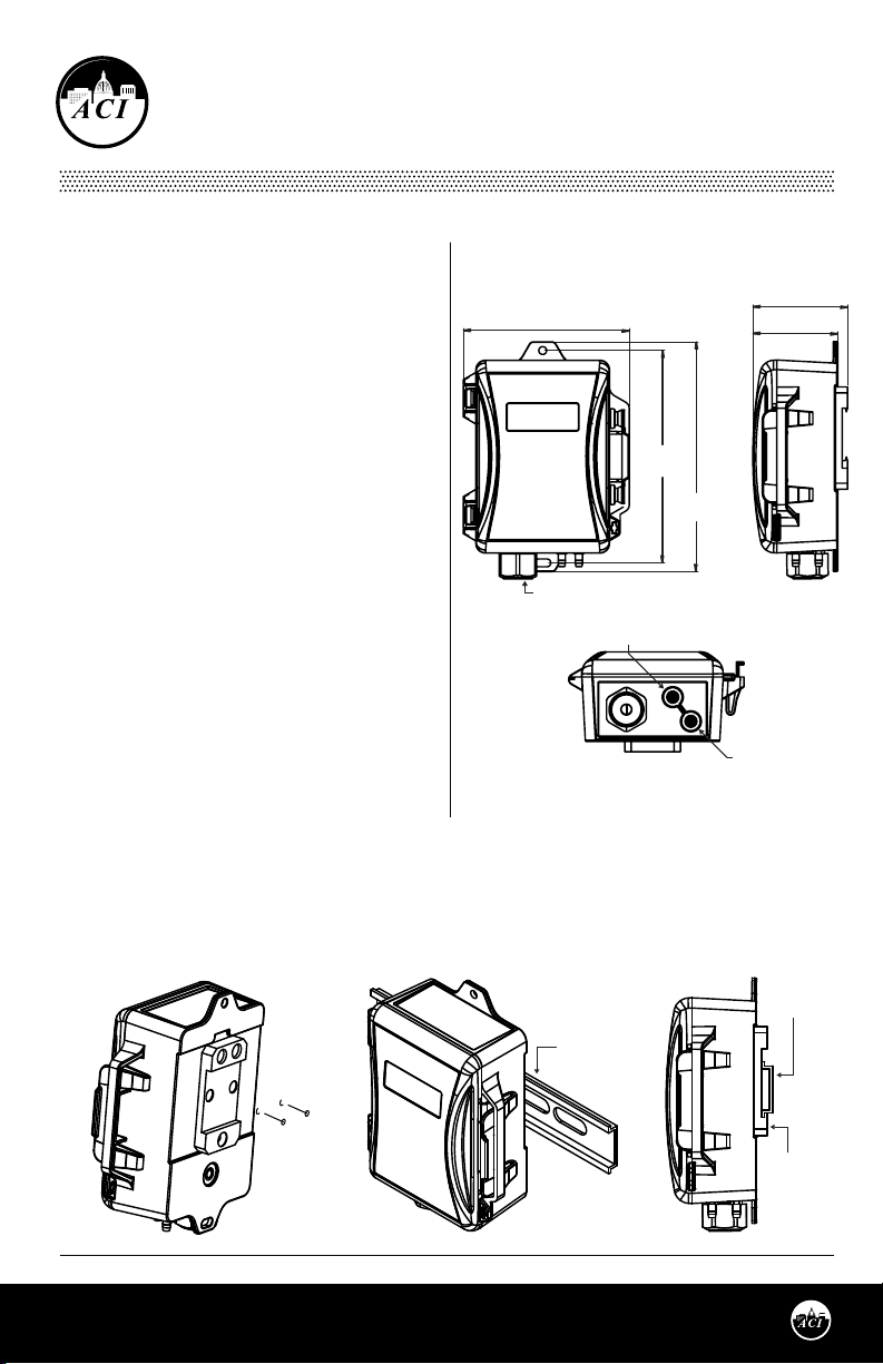
FIGURE 1: DLP DIMENSIONS
4.35"
(110.43 mm)
2.48"
(62.99 mm)
2.23"
(56.52 mm)
transmitter.
GENERAL INFORMATION
The DLP Series is based on a piezoresistive, silicon
sensing element which senses Dierential Pressure
and provides an analog output. Field selectable
analog outputs include 0-5 and 0-10 VDC, or 4-20
mA which correlate to a uni or bi-directional
pressure range from 0-0.1” up to 0-40” of water
column, depending on your model selection. Each
unit has up to 8 eld selectable, uni or bi-directional
ranges (see Figure 6 p. 3).
CORDGRIP /
1/2 “ CONDUIT FITTING
MEDIA
The DLP can be used to monitor the dierential
pressure in any application that uses dry air or inert
gas.
Mounting
Find a suitable location for the enclosure. The DLP
has 2 two mounting holes located on the top and
bottom anges. Drill pilot holes for the (2) #8 x 3/4”
self-drilling screws(supplied). Use the enclosure ange as a guide, or use the dimensions listed in Figure 1.
Mount the unit vertically with the brass ttings pointing towards the ground. This ensures that any
condensation that may form in the tubing does not have an eect on the pressure sensor. If mounting the
unit horizontally, a slight zero shift may occur and care must be taken to prevent moisture from building
up in the sensor.
5.56"
(141.29 mm)
6.02"
(152.82 mm)
HIGH PRESSURE PORT
-H
-L
LOW PRESSURE PORT
FIGURE 2: DIN RAIL MOUNTING
Automation Components, Inc.
2305 Pleasant View Road | Middleton, WI 53562
Phone: 1-888-967-5224 | Website: workaci.com
Page 1
DIN RAIL
DIN RAIL
DIN RAIL
CLIP
Version: 15.0
Version: 15.0
I0000777
I0000777
Page 2
DIN RAIL MOUNTING (Optional)
Attach the DIN Rail Mounting accessory to the
back of the enclosure using the two screws
provided. To mount the sensor on the DIN Rail,
place the bottom of the DIN Rail Clip into the
35mm DIN Rail and push the unit upward to
engage the spring clip. Now press the top of
the unit back until it locks into place - see
FIGURE 2 (p.1).
PITOT TUBE INSTALLATION
(Optional)
Slip the rubber washer over the threaded end
of the pitot tube, keeping the washer as close
to the threaded end as possible. Fasten the
pitot into the threaded insert on the back of
the enclosure. Press the rubber washer against
the enclosure - see FIGURE 3.
Tubing Setup When Pitot Tube is Installed
Units will be shipped with silicone tubing
attached to the high and low pressure barb
ttings. The silicone tubing will need to be
removed from the High Pressure (H) barb
tting and secured onto the pitot tube barb
tting. This will leave the high pressure barb
tting open to atmosphere, and the Low
pressure barb tting remaining at default
setup.
Pressure Connections
The recommended connection tubing is ¼”
O.D push-on tubing (1/8” to 3/16” I.D.). For best
results, all tubing lengths should be limited to
a maximum length of 75 feet (23 meters).
Longer runs will aect the response time.
FIGURE 3: PITOT TUBE INSTALLATION
Move Tubing
from High port to
Pitot tube
HIGH PRESSURE PORT
LOW PRESSURE PORT
FIGURE 5: MEASURING DIFFERENTIAL
PRESSURE ACROSS FILTER
FIGURE 4: DUCT STATIC INSTALLATION
DRILL Ø 7/16”
(11.1125 mm)
HOLE
Automation Components, Inc.
2305 Pleasant View Road | Middleton, WI 53562
Phone: 1-888-967-5224 | Website: workaci.com
Page 2
LOW
A/SPT
A/VPT
POLY TUBING
HIGH
FILTER
DIRECTION
OF AIR FLOW
Version: 15.0
I0000777
Page 3
WIRING
PRECAUTIONS
FIGURE 6: SW1 and SW3 OUTPUT
SWITCHES
• Remove power before wiring. Never
connect or disconnect wiring with
power applied.
• When using a shielded cable, ground the
shield only at the controller end.
Grounding both ends can cause a ground
loop.
• It is recommended you use an isolated
UL-listed class 2 transformer when
powering the unit with 24 VAC. Failure to
wire the devices with the correct polarity
when sharing transformers may result in
Vout
mA
SW1
5V
SW3
BI
Pa
A
1 2 3 4 5
1
ON
OFF
UNI
10V
inWC
B
2
O
damage to any device powered by the
shared transformer.
• If the 24 VDC or 24VAC power is shared with devices that have coils such as relays, solenoids, or
other inductors, each coil must have an MOV, DC/AC Transorb, Transient Voltage Suppressor (ACI
Part: 142583), or diode placed across the coil or inductor. The cathode, or banded side of the DC
Transorb or diode, connects to the positive side of the power supply. Without these snubbers,
coils produce very large voltage spikes when de-energizing that can cause malfunction or
destruction of electronic circuits.
TABLE 1: WIRING CONNECTIONS
OUTPUT SIGNAL
0-5 VDC
0-10 VDC
4-20 mA
4-20 mA
N/A = Not Applicable
N/C = No Connection
OUTPUT MODE
(SW1)
Vout
Vout
mA
mA
OUTPUT SIGNAL
(SW3 Position 4)
5 V
10 V
N/A
N/A
SUPPLY VOLTAGE
VAC/VDC
VAC/VDC
VDC
VAC
WIRE CONNECTIONS
BLACK
RED
COM
V+
COM
V+
N/C
V+
COM
V+
WHITE
VOUT
VOUT
N/C
N/C
YELLOW
N/C
N/C
IOUT
IOUT
FIGURE 7: WIRING CONNECTIONS
2-Wire, 4-20 mA
DLP
YELLOW
WHITE
VOUT
BLACK
COM
Digital Controller
AI1
V+
RED
V+ IOUT
Automation Components, Inc.
2305 Pleasant View Road | Middleton, WI 53562
Phone: 1-888-967-5224 | Website: workaci.com
3-Wire, 0-5 V / 0-10 V
DLP
YELLOW
WHITE
RED
VOUT
COM
V+ IOUT
Page 3
BLACK
Digital Controller
24 VAC/DC POWER
AI1
COM
SUPPLY
-
+
Version: 15.0
I0000777
Page 4

Open the cover of the enclosure. ACI recommends 16 to 26 AWG twisted pair wires or shielded cable for
all transmitters. Twisted pair may be used for 2-wire current output transmitters or 3-wire for voltage
output. Connect the wires to the unit’s nger push-button terminal blocks. Each DLP unit can be
congured to three output signals: 4-20 mA, 0-5 V or 0-10 V. Use the Wiring Connections and diagrams
to determine the proper wiring for your application. See TABLE 1 (p.3) for Output Mode and Output
Signal switch positions.
Note: When using 1/2” conduit, the strain relief tting must be removed from the enclosure.
Note: Make sure that any conduit or metal ttings do not come in contact with the circuit board.
TABLE 2: STANDARD MODEL NUMBERS
OUTPUT SIGNAL
A/DLP-001-W-U-N-A-0
A/DLP-010-W-U-N-A-0
A/DLP-040-W-U-N-A-0
A/DLP-001-W-U-N-A-3
A/DLP-010-W-U-N-A-3
A/DLP-040-W-U-N-A-3
A/DLP-001-W-U-D-A-0
A/DLP-010-W-U-D-A-0
A/DLP-040-W-U-D-A-0
A/DLP-001-W-U-D-A-3
A/DLP-010-W-U-D-A-3
A/DLP-040-W-U-D-A-3
ITEM #
140769
140774
140777
141072
141074
141076
140773
140776
140778
141073
141075
141077
DESCRIPTION
0-0.1", 0.2", 0.5", 1", Without Display
0-1", 2", 5", 10", Without Display
0-10", 20", 30", 40", Without Display
0-0.1", 0.2", 0.5", 1", Without Display, With Pitot Tube and DIN Rail Clip
0-1", 2", 5", 10", Without Display, With Pitot Tube and DIN Rail Clip
0-10", 20", 30", 40", Without Display, With Pitot Tube and DIN Rail Clip
0-0.1", 0.2", 0.5", 1", With Display
0-1", 2", 5", 10", With Display
0-10", 20", 30", 40", With Display
0-0.1", 0.2", 0.5", 1", With Display, Pitot Tube, and DIN Rail Clip
0-1", 2", 5", 10", With Display, Pitot Tube, and DIN Rail Clip
0-10", 20", 30", 40", With Display, Pitot Tube, and DIN Rail Clip
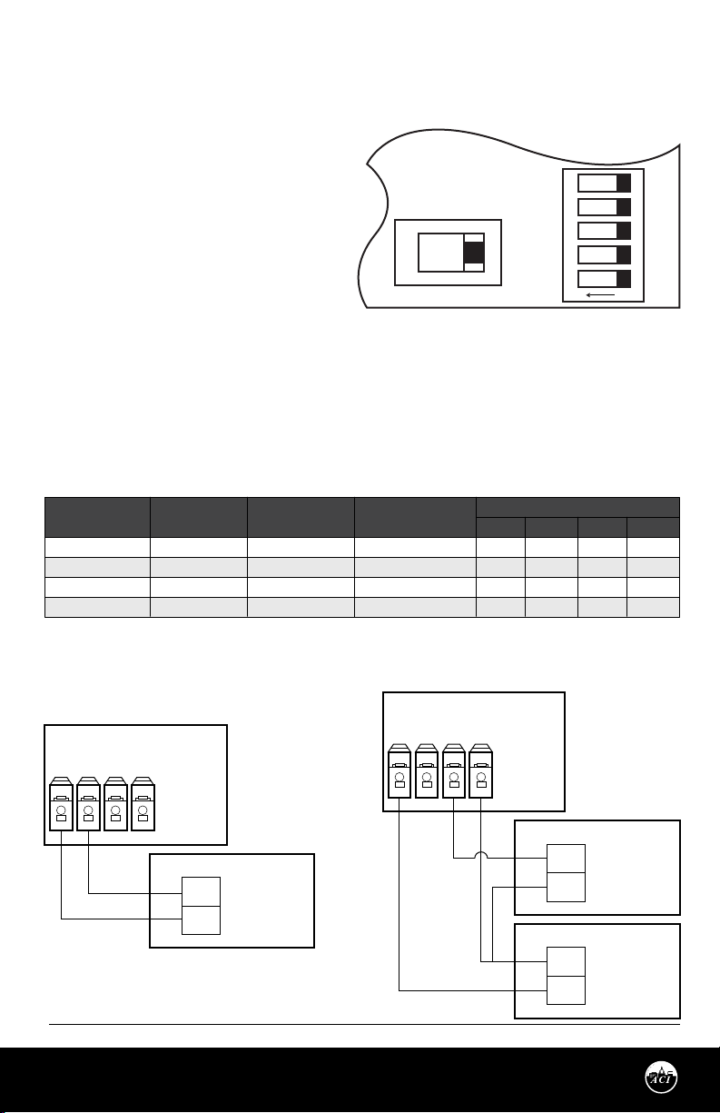
ZERO FUNCTION
FIGURE 8: AUTO ZERO BUTON - SW2
The DLP unit should be “ZEROED” before
pressure is applied to the unit. The zero button
is used to cancel out any osets caused by
installation and sensor drift. The Zero
adjustment must be performed with NO
pressure applied to either side of the sensor.
AUTO
ZERO
SW2
Remove the tubing connected to the H(High)
and/or L(Low) pressure ttings. Push “ZERO”
button for more than three seconds before installation or whenever necessary.
For units with LCD display, “AUTOZERO” icon will be on when the unit enters zero mode. If zeroing
process is successful, the “AUTOZERO” icon will ash twice.
PRESSURE RANGE SELECTION
If a custom calibrated pressure range is ordered, DO NOT change the Pressure Range Selection DIP switch
settings. Table 2 lists ACI’s 12 standard model #’s.
Page 4
Automation Components, Inc.
2305 Pleasant View Road | Middleton, WI 53562
Phone: 1-888-967-5224 | Website: workaci.com
Version: 15.0
I0000777
Page 5

UNIDIRECTIONAL AND BIDIRECTIONAL
MODE
The DLP can operate in either unidirectional mode (0 – X
inWC) or bidirectional mode (± X inWC). Each unit could have
up to eight eld selectable, uni or bidirectional ranges.
TABLE 3: MAXIMUM PRESSURE
ACI Part #
Maximum Pressure
(inWC)
DLP-001-W
DLP-010-W
DLP-040-W
1
10
40
CAUTION
• See TABLE 3 for your DLP model’s maximum pressure.
• DO NOT switch pressure range or output mode when POWER is ON. Make sure POWER to the
unit is OFF. Failure to do so WILL NOT ALLOW any new switch settings to take place.
• Choose differential pressure range based on the expected differential pressure in your
application. Move switches to the correct positions and THEN POWER ON the transmitter.
FIGURE 9: SWITCH SETTINGS
[UNIDIRECTIONAL] DLP-001-W
0 to 1 inWC
BI
5V
Po
A
1
[UNIDIRECTIONAL] DLP-010-W
0 to 10 inWC
BI
5V
Po
A
1
[UNIDIRECTIONAL] DLP-040-W
0 to 40 inWC
BI
5V
Po
A
1
[BIDIRECTIONAL] DLP-001-W
-1 to 1 inWC
BI
5V
Po
A
1
[BIDIRECTIONAL] DLP-010-W
-10 to 10 inWC
BI
5V
Po
A
1
[BIDIRECTIONAL] DLP-040-W
-40 to 40 inWC
BI
5V
Po
A
1
UNI
10V
inWC
B
1 2 3 4 5
2
ON
UNI
10V
inWC
B
1 2 3 4 5
2
ON
UNI
10V
inWC
B
1 2 3 4 5
2
ON
UNI
10V
inWC
B
1 2 3 4 5
2
ON
UNI
10V
inWC
B
1 2 3 4 5
2
ON
UNI
10V
inWC
B
1 2 3 4 5
2
ON
0 to 0.5 inWC
BI
5V
Po
A
1 2 3 4 5
1
ON
0 to 5 inWC
BI
5V
Po
A
1 2 3 4 5
1
ON
0 to 30 inWC
BI
5V
Po
A
1 2 3 4 5
1
ON
-0.5 to 0.5 inWC
BI
5V
Po
A
1 2 3 4 5
1
ON
-5 to 5 inWC
BI
5V
Po
A
1 2 3 4 5
1
ON
-30 to 30 inWC
BI
5V
Po
A
1 2 3 4 5
1
ON
UNI
10V
inWC
B
2
UNI
10V
inWC
B
2
UNI
10V
inWC
B
2
UNI
10V
inWC
B
2
UNI
10V
inWC
B
2
UNI
10V
inWC
B
2
0 to 0.2 inWC
BI
5V
Po
A
1 2 3 4 5
1
ON
0 to 2 inWC
BI
5V
Po
A
1 2 3 4 5
1
ON
0 to 20 inWC
BI
5V
Po
A
1 2 3 4 5
1
ON
-0.2 to 0.2 inWC
BI
5V
Po
A
1 2 3 4 5
1
ON
-2 to 2 inWC
BI
5V
Po
A
1 2 3 4 5
1
ON
-20 to 20 inWC
BI
5V
Po
A
1 2 3 4 5
1
ON
UNI
10V
inWC
B
2
UNI
10V
inWC
B
2
UNI
10V
inWC
B
2
UNI
10V
inWC
B
2
UNI
10V
inWC
B
2
UNI
10V
inWC
B
2
0 to 0.1 inWC
BI
5V
Po
A
1 2 3 4 5
1
ON
0 to 1 inWC
BI
5V
Po
A
1 2 3 4 5
1
ON
0 to 10 inWC
BI
5V
Po
A
1 2 3 4 5
1
ON
-0.1 to 0.1 inWC
BI
5V
Po
A
1 2 3 4 5
1
ON
-1 to 1 inWC
BI
5V
Po
A
1 2 3 4 5
1
ON
-10 to 10 inWC
BI
5V
Po
A
1 2 3 4 5
1
ON
UNI
10V
inWC
B
2
UNI
10V
inWC
B
2
UNI
10V
inWC
B
2
UNI
10V
inWC
B
2
UNI
10V
inWC
B
2
UNI
10V
inWC
B
2
Automation Components, Inc.
2305 Pleasant View Road | Middleton, WI 53562
Phone: 1-888-967-5224 | Website: workaci.com
Page 5
Version: 15.0
I0000777
Page 6

Unidirectional Mode
• DIP switch SW3 position ve set at UNI side.
• DIP switch SW3 positions one and two are for Pressure Range Selection
Bidrectional Mode
• DIP switch SW3 position ve set at BI side.
• DIP switch SW3 positions one and two are for Pressure Range Selection.
Note: In Bidirectional mode, a value of 0 inWC will have an output equal to 50% of the output signal range
(12mA, 2.5V, 5V).
ADDITIONAL LCD FEATURES
LCD Engineering Units Adjustment
This option is ONLY for units with LCD display. Switch DIP switch SW3 position three to select Pa or inWC.
If switched with power on, unit change will not take place until power is cycled.
“Out Of Range”
“OUT OF RANGE” icon will be on when dierential pressure is over or under the minimum or maximum
pressure range selected. If a DLP unit is outputting “OUT OF RANGE”, please turn o the unit immediately,
and check the pressure input with a gauge or other test instrument. Once the pressure has been veried,
set the Pressure Range Selection DIP switch to the proper positions based upon your maximum expected
dierential pressure.
CALIBRATION
DLP utilizes a digital pot for Span calibration and is factory set. There is no Span potentiometer for
adjustment. In the event you require Span calibration, the unit must be sent back to ACI.
The Oset can be adjusted using the Auto Zero function discussed on pg 4. Drift is a function of stress
relaxation over time and this results in the oset shifting, and not the span . Periodically re-zeroing the
device will eliminate the eect of drift.
Automation Components, Inc.
2305 Pleasant View Road | Middleton, WI 53562
Phone: 1-888-967-5224 | Website: workaci.com
Page 6
Version: 15.0
I0000777
Page 7

PRODUCT SPECIFICATIONS
SPECIFICATIONS
Supply Voltage:
Supply Current:
Output Signals:
Response Time (0-100% FSO):
Output Update Rate:
Accuracy¹:
Zero Function:
Thermal Effects²:
Proof Pressure / Burst Pressure³:
Operating Temperature Range:
Compensated Temperature Range:
Storage Temperature Range:
Operating Humidity Range:
Media Types:
Enclosure Material / Flammability Rating:
Wiring Connections:
Conduit Knockouts:
Pressure Fitting Material:
Tubing Size Accepted:
Note: Accuracy includes linearity, hysteresis & repeatability @ 71°F (21.5°C)
Note: Shift is relative to 71°F (21.5°C)
4-20 mA Output: 16-36 VDC (250 Ω Load max.) / 22-36 VDC (500 Ω Load max.)
0-5 VDC / 0-10 VDC Output: 16-36 VDC / 24 VAC (+/- 10%)
4-20 mA Output: 24 mA minimum | 0-5 VDC / 0-10 VDC Output: 6 mA maximum
Current Output: 4-20 mA, 2-Wire (Standard); (Current limited to 21.4 mA max)
Voltage Signals: 0-5 VDC / 0-10 VDC, 3-Wire; Output limited @ 5.25 & 10.5 VDC)
8 seconds
1 second
+/- 0.5% FSO; +/- 0.25% (Only for Specied Range)
Pushbutton Zero Function
+/- 0.067% FSO / °F (0.12% FSO / °C)
A/DLP-001: Proof: 270 inWC (67.2 kPa) | Burst: 415 inWC (103.3 kPa) for 1 inWC (249.8 Pa)
A/DLP-010: Proof: 350 inWC (87.12 kPa) | Burst: 550 inWC (136.9 kPa) for 10 inWC (2490.8 Pa)
A/DLP-040: Proof: 562 inWC (140 kPa) | Burst: 1004.7 inWC (250 kPa) for 40 inWC (9963.6 Pa)
-4 to 185 °F (-20 to 85 °C)
32 to 122 °F (0 to 50 °C)
-22 to 185 °F (-30 to 85 °C)
10 to 95% RH, non-condensing
Dry air or inert non-conductive gases
Flame Retardant Polycarbonate; UL94-5VA
Finger Pushbutton (Spring) Terminal Blocks; accepts 16-24 AWG wires
Watertight Cordgrip Installed (1/2" NPT Conduit ttings accepted when Cordgrip removed)
Nickel Plated Brass or Stainless Steel
1/4" O.D. x 0.170" I.D. Poly Tubing
W.E.E.E. DIRECTIVE
At the end of their useful life the packaging and product should be disposed of via a suitable recycling
centre. Do not dispose of with household waste. Do not burn.
WARRANTY
The ACI DLP is covered by ACI’s Five (5) Year Limited Warranty, which is located in the front of ACI’S
SENSORS & TRANSMITTERS CATALOG or can be found on ACI’s website: www.workaci.com.
Page 7
Automation Components, Inc.
2305 Pleasant View Road | Middleton, WI 53562
Phone: 1-888-967-5224 | Website: workaci.com
Version: 15.0
I0000777
 Loading...