

Page 1

1
Synthesis User Guide
Using Synplify-Pro to target
Speedster22i HD devices
UG018 – April 15, 2013
UG018, April 15, 2013
Page 2

Table of Contents
Introduction ................................ ................................................................ ....... 3
Synplify Pro Introduction .................................................................................. 4
Resource Sharing .......................................................................................................................... 6
Verilog ............................................................................................................................................ 6
Place and Route ............................................................................................................................ 7
Timing Report ................................................................................................................................ 7
Implementation Result ................................................................................................................... 7
Constraints ..................................................................................................................................... 7
Options .......................................................................................................................................... 7
Synthesis Optimization Recommendations .................................................... 8
Hanging Nets ......................................................................................................................... 8
Clock Constraints ................................................................................................................... 9
Pipelining ............................................................................................................................... 9
Retiming ................................................................................................................................. 9
Memories ............................................................................................................................. 10
Block RAM (BRAM) ...................................................................................................................... 10
Local Ram (LRAM) ....................................................................................................................... 12
Finite State Machines .......................................................................................................... 12
Finite State Machine (FSM) Compiler........................................................................................... 12
Replication of States that have high fan-ins ................................................................................. 13
Example Synplify-Pro Project File ................................................................. 15
Revision History .............................................................................................. 17
2 UG018, April 15, 2013
Page 3
3
Synthesis User Guide
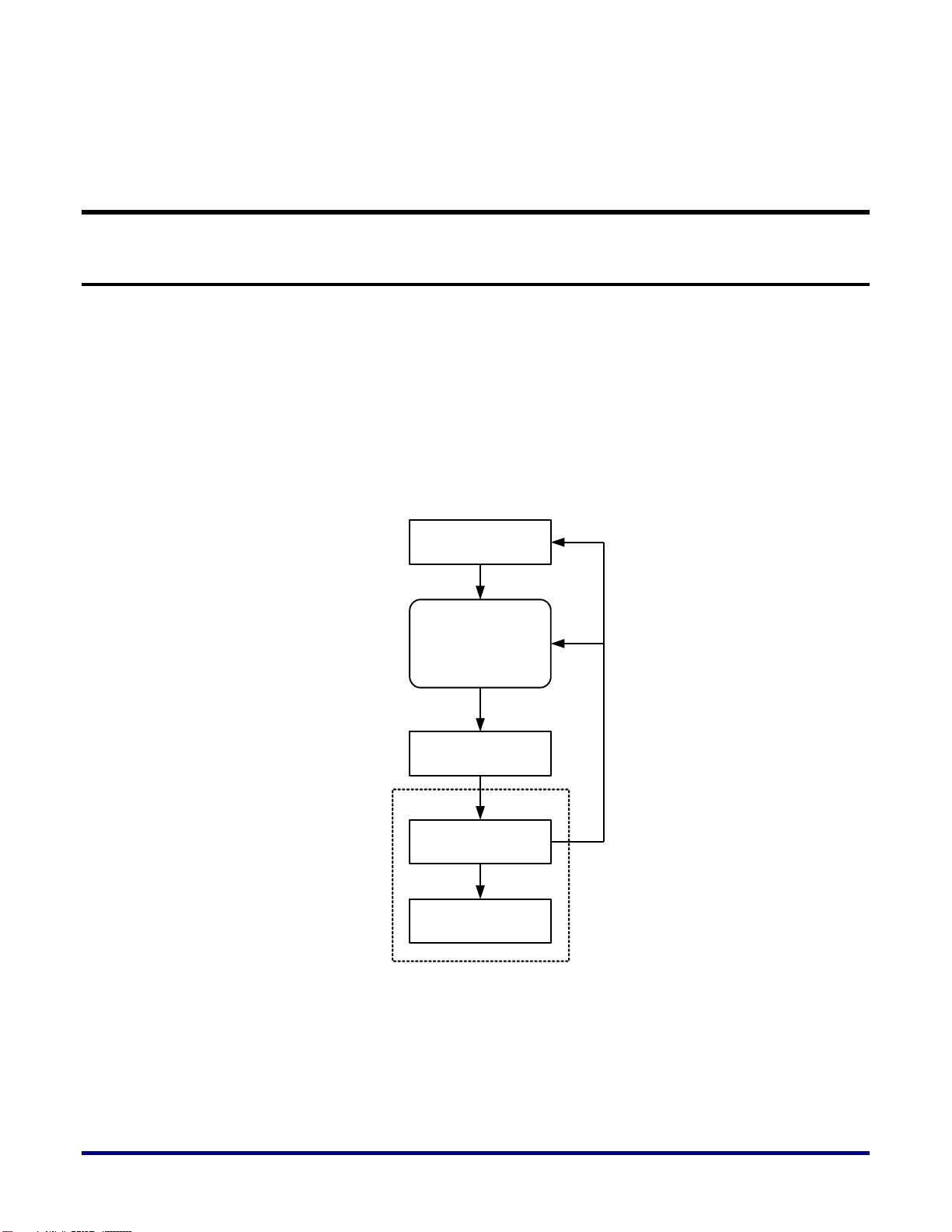
RTL Design
Mapped Netlist
Synthesis using
Synplify Pro
Place and Route
ACE
Bitstream Generation
If Timing
Not Met
Introduction
This User Guide describes how to use Synplify Pro from Synopsys to synthesize a design and
generate a netlist for implementation on an Achronix Speedster22i HD device. Suggested
Optimization Techniques are also included.
Synplify-Pro reads in standard RTL and outputs a Mapped netlist which is used by the
Achronix CAD Environment (ACE) tool. The netlist file uses a .vma extension.
A high level overview of the Achronix design flow is shown in Figure 1 below.
Figure 1 – Synthesis Flow
UG018, April 15, 2013
Page 4
Synplify Pro Introduction
We assume you have Synplify-Pro installed and the ‘synplify_pro’ command added to your
$PATH. This guide uses Unix for examples, the Windows version of Synplify Pro has the
same options.
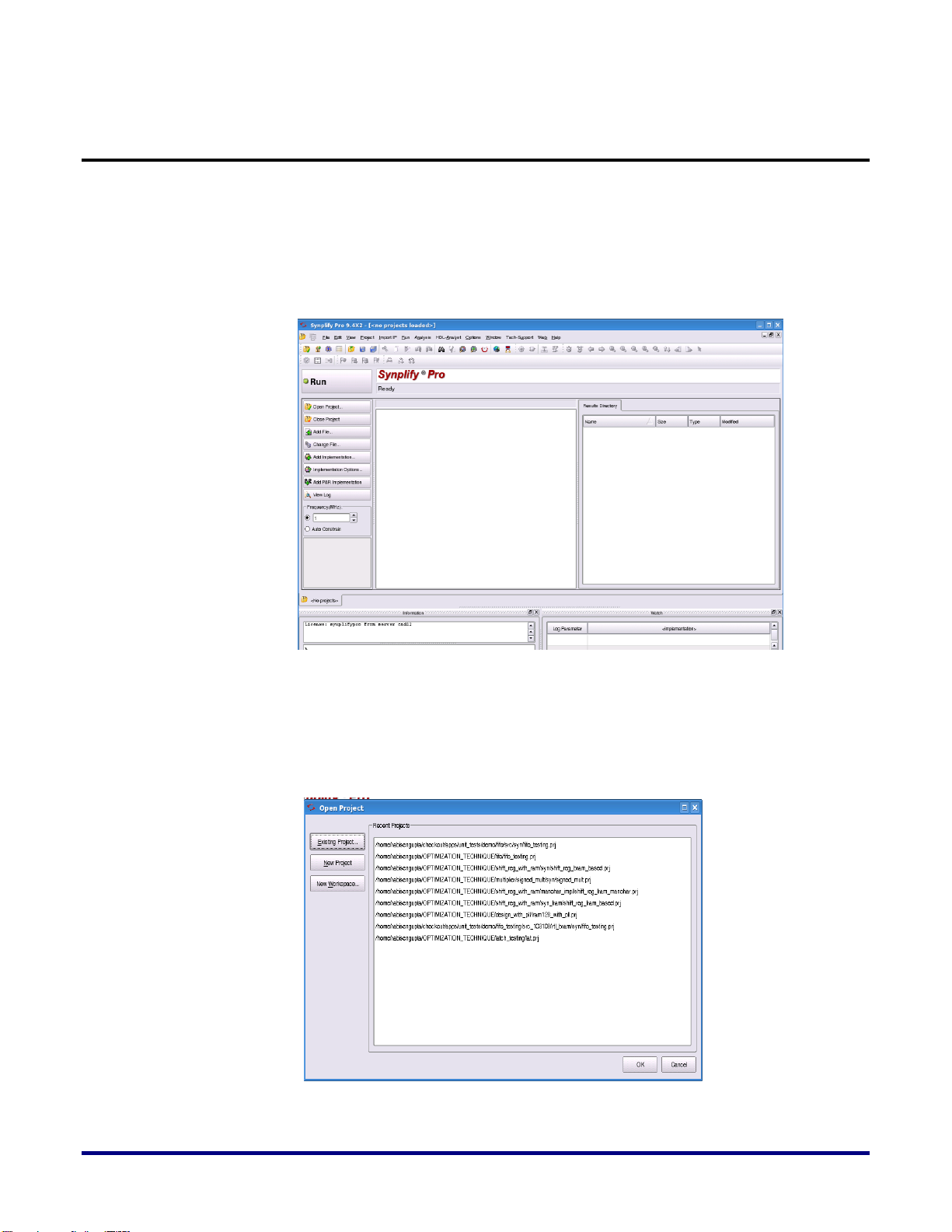
In the Linux command shell type “synplify_pro” to invoke the Synplify-Pro Synthesis tool.
When invoked, the following window will be displayed:
Figure 2 – Synplify Pro invoked from the command shell
Click on the “Open Project” button from the left-side and the following dialog-box will
appear (shown in Figure 3).
Figure 3 – Dialog Box to select the “New Project”
4 UG018, April 15, 2013
Page 5
5
Select or click on the “New Project” button, then the following window will appear
(shown in Figure 4):
Figure 4 – Properly select the Project database for the synthesis.
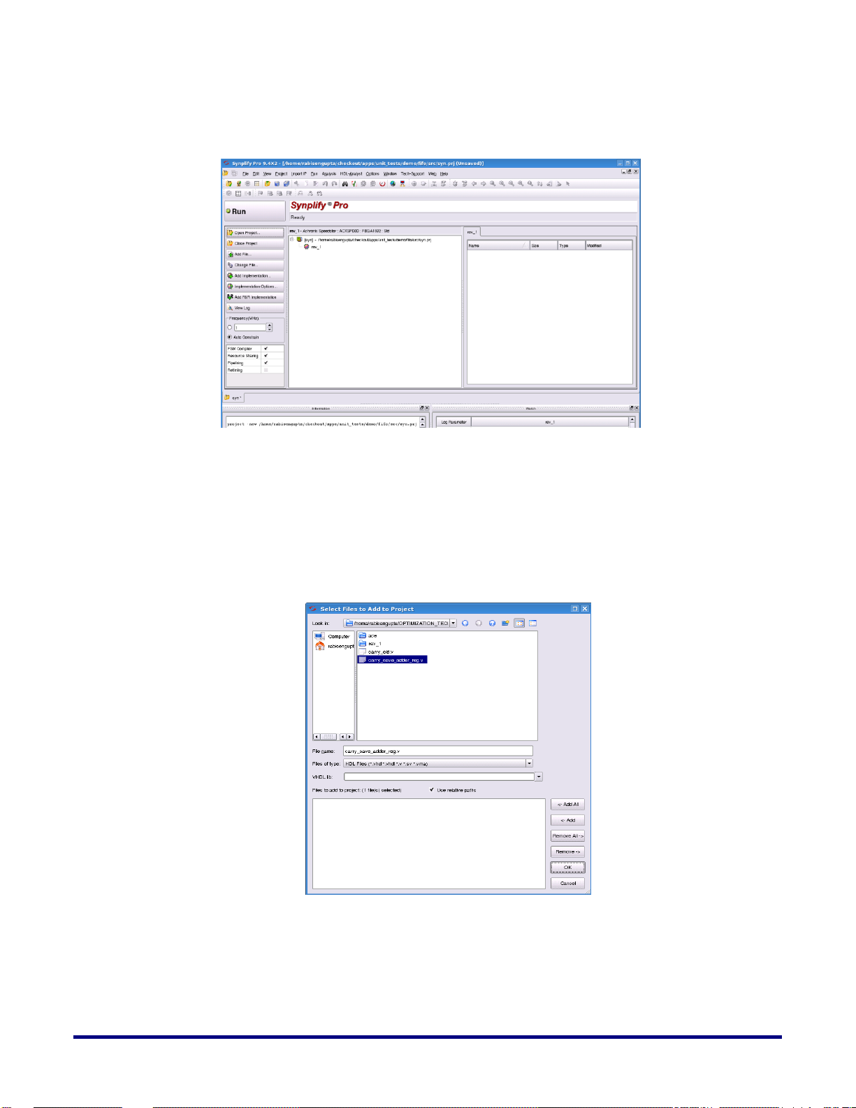
After selecting and saving the project file inside the desired directory path, you will have to
add the source RTL files. There are two ways to add the source RTL files. One is using the
“Add File” option from the Left menu bar and the other one is to ‘right click’ on the project
file and select “Add Source File”. Selecting the source will direct the user to a dialog box of
RTL files. Below is an example of the dialog box:
Figure 5 – Add the source file under the user’s project directory
From this dialog box “Select Files to Add to Project” choose your RTL files and then click
“Add” followed by “OK”. The Verilog/VHDL file(s) will now be added to the project for
synthesis.
UG018, April 15, 2013
Page 6
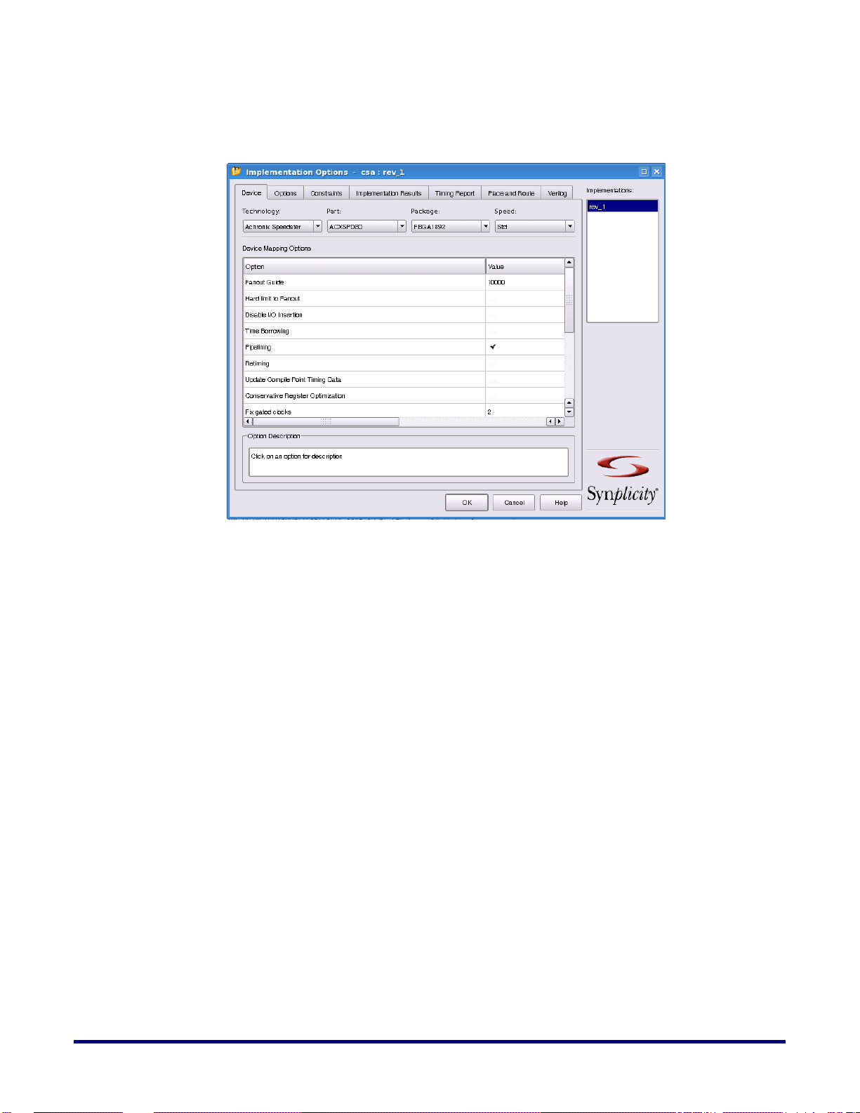
After adding the RTL files, the next step is to set the Implementation Options. By selecting
this option the following window will appear (Shown in Figure 6):
Figure 6 – Implementation Options
This dialog box shows the default options. For example the “Fanout Guide” defaults to
10,000, but you can modify this to any value. You can also check or uncheck the “Hard limit
to Fanout” option as well as the “Disable I/O Insertion” option.
If you do not want to infer IO buffers during synthesis, you will need to check the box under
the “Value” column. In the “Implementation Options” dialog box, “Device” is selected by
default. You can go through each tab and select the proper option according to your needs.
Here are some Achronix guidelines for these options.
Resource Sharing
Resource sharing can have a significant performance impact on loops and other critical
structures. Reviewing the synthesis results can identify resource sharing, for example
multiplexers in front of multipliers. Turning resource sharing off during synthesis can
improve performance.
Note: In some cases having resource sharing can actually improve performance. It is worth
experimenting as results are very design dependant
Verilog
Under this TAB section the user may define the Top-Level design module name. Achronix
also recommends selecting the Verilog 2001 from the Verilog Language box. The User can
also provide the parameter name of any parameter existing in the design along with a value
for the parameter. If you define the parameters in this manner, Synplify Pro will propagate
this value through the design. In this section the user can also add “Include Path Order” and
6 UG018, April 15, 2013
Page 7

7
“Library Directories”. By default these two boxes are left empty. If user wants to add these
paths, check the + switch and add the desired directory path.
Place and Route
This tab is not presently utilized by the Achronix back-end tool (ACE).
Timing Report
This tab will generate the timing report for the user after synthesis has completed. In this tab
there are two options: i) Number of Critical paths which will depict the specified total
number critical paths found by the synthesis tool after successful completion of synthesis. ii)
Number of Start/End points, which is the number of paths the user wants displayed that
contain the same Start and End points.
Implementation Result
In this section users may use his own implementation name, default is set as rev_1. The next
box is the “Results Directory” where users want to save the synthesized netlist file. The third
box is “Results File Name” which directs users to use the synthesized netlist file name. After
selecting accordingly, the user will need to go to the “Constraints” tab.
Constraints
In this sub-section, users will select the clock speed of the design. It is recommended that
users use the proper clock speed in the Frequency Box (default set to 1MHz). If users have
multiple clocks, a constraints file should be added to the Synplify Pro project.
Options
In this section, users may change the design optimization options according to the design.
You will find options for FSM compiler, Resource sharing, Pipelining and Retiming (Register
optimization).
After selecting all the options according to the users design, click “OK” and it will direct the
user to the Synplify Pro main window to run the synthesis. In this main Synplify-Pro
window, click the “RUN” button to start synthesis.
UG018, April 15, 2013
Page 8

Synthesis Optimization Recommendations
There are several recommendations that can be implemented by the user during Synplify-Pro
synthesis. This sections covers:
Hanging Nets
Clock Constraints
Pipelining
Retiming
Memories
o Block RAM (BRAM)
o Local Ram (LRAM)
Finite State Machines
o Finite State Machine (FSM) Compiler
o Replication of States that have high fan-ins
Hanging Nets
Synplify Pro always performs optimization on the redundant or feed-through nets. At times,
the user may want to keep these nets. In order for these nets not to get optimized away
(removed), you will have to do the following:
wire net1 /* synthesis syn_keep = 1 */ ;
wire net2 ;
assign net2 = net1 ;
In this above example, the synthesis tool won’t optimize away (remove) the logic. Instead, it
will infer a buffer between the two wire statements. If it is not specified, the user may not see
the buffer insertion by the tool.
The same is true for sequential logic. If you don’t not want the sequential element optimized
away (removed), the following synthesis directive to be added:
reg net_reg1 /* synthesis syn_preserve = 1 */ ;
always @ (posedge clk)
begin
net_reg1 <= some_net ;
end
8 UG018, April 15, 2013
Page 9

9
Clock Constraints
-disable
Disables a previous set clock constraint.
-virtual
Specifies arrival and required times on top level ports that are
enabled by clocks external to the chip (or block) that are being
synthesized. When specifying a name for a virtual clock, the
field can contain a unique name not associated with any port or
instance in the design.
{clockObject}
This is a required parameter that specifies the name of the clock
object. Clocks can be defined on the following objects:
Top-level input ports (p:)
Nets (n:)
Instances (i:)
Output pins of instantiated cells (t:)
Clocks defined on any of the following objects WILL NOT be
It is a requirement for the user to define all clocks with a specific duty cycle and frequency or
clock period goal. The user can have multiple clocks with different clock frequencies. The
default frequency can be set for all clocks with the set_option -frequency Tcl command in the
Synplify project file. If the user does not specify a global frequency, the timing analyzer uses
a default. Achronix does not recommend using the default. Use the define_clock timing
constraint to override the default and specify unique clock frequency goals for each clock
signal. Additionally, the user can use the define_clock timing constraint to set the clock
frequency for a clock signal output from clock divider logic. The clock name is the output
signal name for the register instance. When constraining a differential clock the user only
needs to constrain the positive input.
Pipelining
When this switch is enabled in synthesis project file, the synthesis tool uses register balancing
and pipeline registers on multipliers and ROMs. Pipelining is the process of splitting logic
into stages so that the first stage can begin processing new inputs while the last stage is
finishing the previous inputs. This ensures better throughput and faster circuit performance.
If you are using selected technologies which use pipelining, you can also use the related
technique of retiming to improve performance. Same as enabling the Pipelining option on the
Options panel of the Implementation Options dialog box.
Retiming
When this switch is enabled the synthesis tool tries to improve the timing performance of
sequential circuits. The retiming process moves storage devices (flip-flops) across
computational elements with no memory (gates/LUTs) to improve the performance of the
circuit. This option also adds a retiming report to the log file. Same as enabling the Retiming
option on the Options panel of the Implementation Options dialog box. Use the
syn_allow_retiming attribute to enable or disable retiming for individual flip-flops.
Pipelining is automatically enabled when retiming is enabled.
Syntax:
define_clock [ -disable ] [ -virtual] {clockObject} [ -freq MHz | -period ns ] [ -clockgroup domain ]
Option descriptions:
UG018, April 15, 2013
Page 10

honored:
Top-level output ports
Input pins of instantiated gates
Pins of inferred instances
-freq
Defines the frequency of the clock in MHz. The user can specify
either this or -period, but not both
-period
This parameter allows the user to specify the period of the clock
in nanoseconds. The user can specify either this or -freq, but
not both.
-clockgroup
This parameter allows the user to specify clock relationships.
The user assigns related (synchronized) clocks to the same clock
group and unrelated clocks in different groups. The synthesis
tool calculates the relationship between clocks in the same clock
group, and analyzes all paths between them. Paths between
clocks in different groups are ignored (false paths). An example
usage with this parameter is provided later in this document
for more information.
Below are examples of clock-constraint commands for a multiple clock domain design:
define_clock {n:spi_refclk} -name {n:spi_refclk} -freq 400 -clockgroup default_clkgroup_0
define_clock {n:rx_sclk} -name {n:rx_sclk} -freq 100 -clockgroup default_clkgroup_0
define_clock {p:spi_tx_sclk[0]} -name {p:spi_tx_sclk[0]} -freq 100 -clockgroup default_clkgroup_1
define_clock {p:spi_tx_sclk[1]} -name {p:spi_tx_sclk[1]} -freq 100 -clockgroup default_clkgroup_2
define_clock {p:spi_tx_sclk[2]} -name {p:spi_tx_sclk[2]} -freq 100 -clockgroup default_clkgroup_3
define_clock {p:spi_tx_sclk[3]} -name {p:spi_tx_sclk[3]} -freq 100 -clockgroup default_clkgroup_4
define_clock {p:spi_tx_sclk[4]} -name {p:spi_tx_sclk[4]} -freq 100 -clockgroup default_clkgroup_5
define_clock {p:spi_tx_sclk[5]} -name {p:spi_tx_sclk[5]} -freq 100 -clockgroup default_clkgroup_6
Memories
Memories can be instantiated in the RTL, or inferred by the Synthesis tool
Memory instantiation or Memory Insertion by the synthesis tool. If user wants to instantiate
memory inside the RTL code, it is totally technology dependent.
Block RAM (BRAM)
The user can also specify the memory type inside the RTL code in order to have it inferred by
the synthesis tool. Following is the statement to infer memory:
For Verilog:
reg [4:0] mem_array [0:255] /* synthesis syn_ramstyle = "block_ram,no_rw_check" */;
For VHDL:
type array512x36 is array(0 to 511) of std_logic_vector (DW-1 downto 0);
signal mem : array512x36;
10 UG018, April 15, 2013
attribute syn_ramstyle : string ;
attribute syn_ramstyle of mem : signal is "block_ram, no_rw_check";
Page 11

11
During synthesis Synplify Pro will infer the BRAM80K block based on the above coding
style.
UG018, April 15, 2013
Page 12

Local Ram (LRAM)
Distributed RAM or LRAM inferring or instantiation: Synplify-Pro is able to infer (or
instantiate) LRAMs. With the current Synplify release, there must be a register at the output
of the read port or the read address has to be registered to infer the LRAM. Inferred
asynchronous reads from the LRAM are not yet supported. Also, with the current Synplify
release, initializing the LRAM is not yet supported. Both the asynchronous read and the
LRAM initialization are planned for the next release (when it is available). Note the LRAM
initialization is required to support ROMs.
For Verilog:
reg [5:0] addr_reg ;
always @ (posedge clk) addr_reg <= addr_ports ;
reg [9:0] mem_array [0:63] /* synthesis syn_ramstyle=”logic_ram”*/;
For VHDL:
type array63x10 is array(0 to 63) of std_logic_vector (9 downto 0);
signal mem_array : array63x10;
attribute syn_ramstyle : string ;
attribute syn_ramstyle of mem_array : signal is "logic_ram";
Finite State Machines
Finite State Machine (FSM) Compiler
The FSM Compiler is an automatic tool for encoding state machines. FSM coding style in the
RTL design will directly impact performance. User should consider this carefully. By default
Synplify-Pro performance as follows:
0-4 states is Binary Encoding
5-40 states is One Hot Encoding
>40 states is Gray Encoding
If the user wants to specify FSMs differently with attributes, here are the steps:
To generate better results for the state machines :
The software uses optimization techniques that are specifically tuned for FSMs such as reach
ability analysis. The FSM Compiler may convert this encoded state machine into a different
encoding style (to improve speed and area utilization) without changing the source. For
example, the user can use the one-hot style to improve results.
To debug the state machines:
State machine description errors result in unreachable states, so if the user has errors, the user
will have fewer states. The user can then check whether the source code describes the state(s)
correctly. The user can also use the FSM Viewer to see a high-level bubble diagrams and
cross-probe from there.
FSM Encoding: For VHDL users
there are two choices to define the encoding via attributes in the RTL code:
Use “syn_encoding” attribute and enable the FSM compiler.
Use “syn_enum_encoding” to define the states (sequential, one-hot, gray, and safe)
and disable the FSM compiler. If the user does not disable the FSM compiler, the
“syn_enum_encoding: values are not implemented. This is because the FSM
compiler, which is a mapper operation, overrides any user attributes for the FSM
12 UG018, April 15, 2013
Page 13

13
encoding. The FSM compiler can be disabled via the GUI or the from the Synplify
project file with the following syntax:
set_option –symbolic_fsm_compiler 0
The user may also direct the synthesis process to deploy a user-defined FSM
encoding. An example:
VHDL:
attribute syn_enum_encoding of state_type: type is “001 010 101” ;
There is a synthesis attribute to turn on/off FSM extraction. By using this attribute the
user can see how state machines are extracted. Setting attributes in the source code is
shown in the following table
Specify a state machine for extraction and optimization syn_state_machine=1
Prevent state machines from being extracted and optimized syn_state_machine=0
An example for VHDL design:
------ Attribute --- attribute syn_state_machine : boolean;
attribute syn_state_machine of tx_training_cstate : signal is true;
An example for Verilog design:
If user does not want to optimize the state machine, add the
syn_state_machine directive to the registers in the Verilog code.
Set the value to 0. When synthesized, these registers are not extracted
as state machines.
reg [39:0] curstate /* synthesis syn_state_machine=0 */ ;
For the above 40 states, Synplify Pro performs Gray encoding. If the user wants to do One
Hot Encoding then he will have to do the following:
reg [39:0] state /* synthesis syn_encoding = "onehot" */ ;
Replication of States that have high fan-ins
Large and complex state machines present another unique challenge in state machine design.
Complex state machines can be made to run faster by actually making them larger, that is by
adding more states. This technique can be counter intuitive as the number of levels of logic
between the states and not the number of states typically limits state machine performance.
The performance of a state machine is limited by both the number of fan‐ins into a given state
and the decisions made in that state. For example, idle type states can have a large number of
inputs plus increased computational load. With the 4‐input LUT architecture of Speedster22i
FPGAs, once the number of fan‐ins exceeds four, another level of logic is needed. An easy method to
reduce the number of fan‐ins is to replicate these states. The duplicated high fan‐in states reduce the
number of inputs, thus reducing the number of levels of logic.
UG018, April 15, 2013
Page 14

Figure 7- Replicated High Fan-in State Example
Both state machines in the above Figure 7 are equivalent in function, but State A is duplicated
in Version II so that A and A1 have two or less return inputs. As a result, if each state has to
deal with two additional inputs, they can now be contained in one 4‐input LUT. Although this
example is simplistic, the methodology can be applied to larger and more complex state
machines.
Fanout Limit:
This fanout limit can also be controller through RTL design. In this case if the user knows
about a net with a high fanout and wants to replicate the cell after a certain fanout is reached,
the following coding style is needed:
wire net1 /* synthesis syn_maxfan = 8 */ ;
Here Synplify Pro will infer a buffer/logic if the fanout limit of the net “net1” exceeds 8.
14 UG018, April 15, 2013
Page 15

15
Example Synplify-Pro Project File
#-- Synopsys, Inc.
#-- Version F-2011.09X Beta
#-- Project file /home/testing_HD.prj
#project files
add_file -verilog "/<path_to_Achronix_software>/Achronixlinux/libraries/device_models/22i_synplify.v"
add_file -vhdl -lib work " package1.vhd"
add_file -vhdl -lib work "top_level.vhd"
#implementation: "rev_1_HD"
impl -add rev_1_HD -type fpga
#
#implementation attributes
set_option -vlog_std v2001
set_option -project_relative_includes 1
set_option -include_path <path_to_Achronix_software>/Achronix-linux/libraries/}
#device options
set_option -technology AchronixSpeedster22iHD
set_option -part ACX22iHD1000
set_option -package FBGA2280
set_option -speed_grade Std
set_option -part_companion ""
#compilation/mapping options
set_option -top_module "<top_level_module_name>"
# mapper_options
set_option -frequency <user’s_desired_frequency>
set_option -write_verilog 0
set_option -write_vhdl 0
# Achronix Speedster22iHD
set_option -maxfan 10000
set_option -disable_io_insertion 0
set_option -retime_registers_forward 0
set_option -time_borrow 0
set_option -pipe 1
set_option -retiming 1
set_option -update_models_cp 0
set_option -fixgatedclocks 3
set_option -fixgeneratedclocks 3
# NFilter
set_option -popfeed 0
set_option -constprop 0
set_option -createhierarchy 0
# sequential_optimization_options
set_option -symbolic_fsm_compiler 1
UG018, April 15, 2013
Page 16

# Compiler Options
set_option -compiler_compatible 0
set_option -resource_sharing 0
# Compiler Options
set_option -vhdl2008 1
#automatic place and route (vendor) options
set_option -write_apr_constraint 1
#set result format/file last
project -result_file "./rev_1_HD/<top_level_module_name>.vma"
impl -active "rev_1_HD"
Note - if the user has a clock-constraint file for synthesis, in this case the user needs to
add the following command inside the synthesis project file:
#CONSTRAINTS
add_file -constraint "./syn.sdc"
16 UG018, April 15, 2013
Page 17
17
Revision History
Date
Version
Revisions
2/6/2012
1.0
Initial Achronix release.
4/15/2013
1.1
Corrected links.
The following table shows the revision history for this document.
UG018, April 15, 2013
 Loading...