

Page 1

Speedster22i
Interlaken User Guide
UG032 – May 15, 2014
UG032, May 15, 2014
1
Page 2

Copyright Info
Copyright © 2014 Achronix Semiconductor Corporation. All rights reserved.
Achronix is a trademark and Speedster is a registered trademark of Achronix
Semiconductor Corporation. All other trademarks are the property of their
prospective owners. All specifications subject to change without notice.
NOTICE of DISCLAIMER: The information given in this document is
believed to be accurate and reliable. However, Achronix Semiconductor
Corporation does not give any representations or warranties as to the
completeness or accuracy of such information and shall have no liability for
the use of the information contained herein. Achronix Semiconductor
Corporation reserves the right to make changes to this document and the
information contained herein at any time and without notice. All Achronix
trademarks, registered trademarks, and disclaimers are listed at
http://www.achronix.com and use of this document and the Information
contained therein is subject to such terms.
UG032, May 15, 2014
2
Page 3

Table of Contents
Copyright Info .................................................................................. 2
Table of Contents ............................................................................ 3
Introduction ..................................................................................... 6
Design Overview ............................................................................. 8
Hierarchy ........................................................................................................... 9
Typical Operation ............................................................................................ 10
Flow Control .......................................................................................................... 10
Start-Up Procedure ................................................................................................ 10
Clocking .......................................................................................................... 12
TX LBUS Interface .......................................................................................... 25
Data Formatting ..................................................................................................... 26
Packet Mode ......................................................................................................... 26
Segment Mode ...................................................................................................... 26
Use of tx_bctlin ...................................................................................................... 27
RX LBUS Interface .......................................................................................... 28
Status/Control Interface ................................................................................... 30
RX Meta Frame Status .......................................................................................... 30
RX Error Status ..................................................................................................... 31
CRC32 Diagnostics Checking................................................................................ 33
Interlaken Status Messaging for the Receiver ........................................................ 33
Interlaken Status Messaging for the Transmitter .................................................... 34
Transmitter Multiple-Use Bits ................................................................................. 34
Receiver Multiple-Use Bits ..................................................................................... 34
Transmitter Flow-Control Inputs ............................................................................. 35
Register Interface ............................................................................................ 36
Description of Feature s ................................................................ 45
Lane Decommission ........................................................................................ 45
Disabling Consecutive Lanes................................................................................. 45
Consecutive Transmit Lanes ............................................................................................ 45
Consecutive Receive Lanes ............................................................................................. 45
Disabling a Single Lane ......................................................................................... 46
Single Transmit Lane ........................................................................................................ 46
Single Receive Lane ......................................................................................................... 46
Link Level Flow Control ................................................................................... 47
UG032, May 15, 2014
3
Page 4

TX Rate Limiting .............................................................................................. 48
Example: Programming the Rate Limiter ............................................................... 49
Error Handling ................................................................................................. 50
Revision History .............................................................................................. 51
UG032, May 15, 2014
4
Page 5

Table of Figures
Figure 1: Shows a block diagram of IIPC with SerDes and user logic interface ............... 8
Figure 2: IIPC Hierarchy .................................................................................................... 9
Figure 3: RX Clock Domains ............................................................................................ 13
Figure 4: TX Clock Domains............................................................................................. 14
Figure 5: Sample TX Waveform with a 512-bit Data Bus ................................................. 25
Figure 6: Sample RX Waveform with a 512-bit Data Bus ................................................ 28
UG032, May 15, 2014
5
Page 6

Introduction
Interlaken is a scalable chip-to-chip interconnect protocol designed to enable transmission speeds
from 10Gbps to 100Gbps and beyond. Using the latest SerDes technology and a flexible protocol
layer, Interlaken minimizes the pin and power overhead of chip-to-chip interconnect and
provides a scalable solution that can be used throughout an entire system. In addition, Interlaken
uses two levels of CRC checking and a self-synchronizing data scrambler to ensure data integrity
and link robustness.
The Achronix Interlaken IP Core (IIPC) is available as hard IP in Speedster22i devices. The IIPC is
a high-performance, low-power and flexible implementation of the Interlaken Protocol. The IIPC
is compliant with the Interlaken Protocol Definition, Revision 1.2, and offers system designers
with a risk-free and quick path for adopting Interlaken as their chip-to-chip interconnect
protocol. The IIPC can be configured to use any number of serial lanes (between 4 to 12) for an
aggregate bandwidth of up to 123 Gbps.
The rest of this document describes the IIPC in detail and provides the information required for
the user to integrate the IIPC into their designs. The document assumes the reader is familiar
with the Interlaken protocol and FPGA design and methodology.
Interlaken is a very flexible and customizable protocol. IIPC supports the following features:
• Designed to take full advantage low-power design flows and methodology
• Automatic scaling of clocks to minimize power consumption
• Support for up to 10.3125Gbps SerDes data rate
• Support for 256 different logical channels
• Robust error condition detection and recovery
• Flexible SerDes interface to accommodate different I/O implementations
• Data striping and de-striping across 4 to 12 lanes
• Programmable BurstMax, BurstShort and MetaFrameSize parameters
• 64/67 encoding and decoding
• Automatic word and lane alignment
• Self-synchronizing data scrambler
• Data bus width of 512 bits
• CRC24 generation and checking for burst data integrity
• CRC32 generation and checking for lane data integrity
• Data scrambling and disparity tracking to minimize baseline wander and maintain DC
balance
• Support for all Synchronization, Scrambler State, Diagnostic, and Skip Word Block Types
• Programmable Rate Limiting circuitry
• Segment-mode and Packet-mode transmission format
UG032, May 15, 2014
6
Page 7

• Segment-mode and Packet-mode receive format
• BurstMax size can be programmed from 64 bytes to 256 bytes in steps of 64 bytes
• Support for minimum BurstShort requirement of 64 bytes up until 256 bytes in steps of
64 bytes but not exceeding BurstMax
• In-band flow control
• Support for link-level flow control
• Flow control mechanism supports stopping packets in mid-stream – head of line
blocking
• Rate matching with granularity of 1 Gbps
• Meta Frame Length programmable between 128 to 8K words
• Support for status messaging
• Lane decommissioning and resiliency
UG032, May 15, 2014
7
Page 8
Design Overview
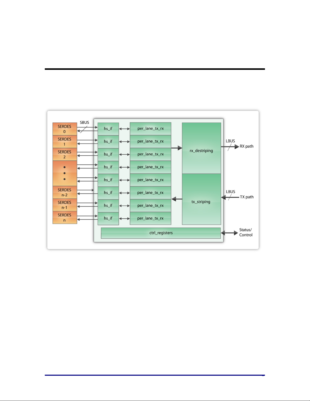
Figure 1 shows a block diagram of the IIPC with SerDes and user logic interfaces implemented in
Speedster22i. The right hand side is the user interface and the left hand side is the SerDes
interface. The IIPC is shown in green and the SerDes blocks in orange.
Figure 1: Shows a block diagram of IIPC with SerDes and user logic interface
UG032, May 15, 2014
8
Page 9
Hierarchy
Interlaken_1_serdes
ACX_INTERLAKEN_TOP
(IIPC core)
Interlaken_1
The interfaced IIPC and SerDes IP is configured using the Achronix Cad Environment (ACE)
Interlaken GUI.
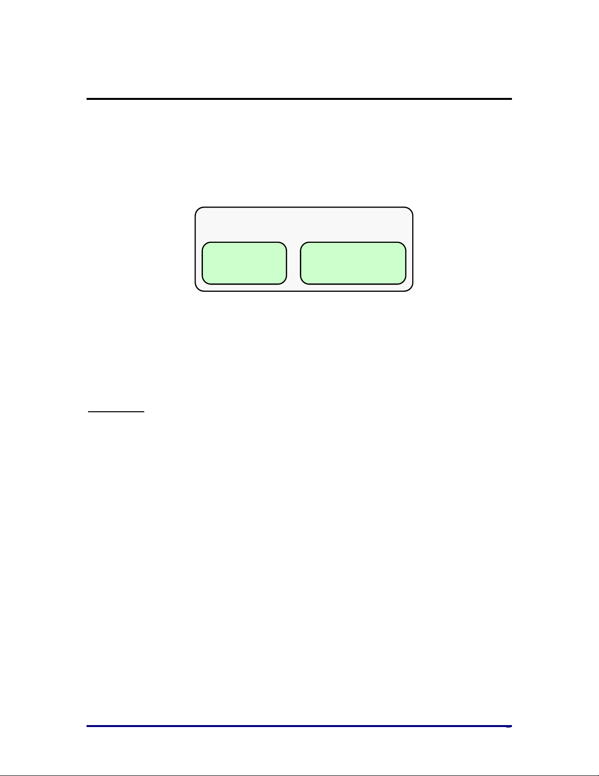
The upper-levels of hierarchy are shown in Figure 2. Note that the text in Figure 2 represents the
name of the module at that level of hierarchy.
Figure 2: IIPC Hierarchy
The top-level wrapper module, Interlaken_1, contains the instantiated hard IIPC block and an
instantiated hard SerDes block for each lane. The module Interlaken_1_serdes wraps the Achronix
SerDes block and sets configuration parameters needed for proper Interlaken operation.
User’s Tasks:
• The ACE Interlaken GUI should be used to configure the Interlaken core. This will
automatically instantiate the SerDes lanes and produces a single top level wrapper that
can be included in your design.
• Connect the Local Bus (LBUS) user-side interface at the fabric to the wrapper
• Provide the appropriate clock signals to the wrapper
UG032, May 15, 2014
9
Page 10

Typical Operation
The IIPC can be used in a variety of applications, and provides the user all of the flexibility
offered by the Interlaken Protocol. The IIPC handles all protocol-related functions needed to
communicate to another device’s Interlaken interface. All handshaking, synchronizing and error
checking are handled by the IIPC. The LBUS is designed to match commonly used packet bus
protocols made common by the SPI4.2 protocol; a detailed description is given in the User
Interfaces section.
User’s Task:
• Provide packet data via the Local Bus (LBUS) TX interface, and receive packet data from
the LBUS RX interface.
Flow Control
Flow control information is automatically extracted by the RX path of the IIPC and presented to
the user. Also, the IIPC’s TX path consists of a single pipeline with a single memory buffer.
User’s Tasks:
1. Build the scheduling mechanism external to the IIPC to mux data from different logical
channels.
2. Monitor the flow control information and ensure proper data transmission through the
IIPC
Start-Up Procedure
The following lists the different operation steps upon IIPC power-up:
1. After the device is powered up and the reset procedure completed, the IIPC TX path
starts transmitting Control/Idle words in order to align and synchronize the receiving
device’s Interlaken interface. Similarly, the IIPC RX path listens for Control/Idle words
and goes through its own synchronization procedure.
2. User’s Task: Set all of the flow control input to the IIPC TX path to the XOFF state to
prevent any real data transfer.
3. The RX path will eventually get aligned and synchronized and signal the user logic that
synchronization is complete.
4. User’s Task: Turn the flow control information from XOFF to XON for any of the
channels that are ready to accept data.
5. Similarly when the other device is ready to receive data, it will send XON information to
the IIPC which in turn will tell the user logic which channels can be used to transmit data
on.
The above list describes a simple and easily-implementable procedure by which to initially
configure the IIPC. The user needs to build a scheduler only to mux data amongst the different
logical channels, and use the flow control information output by the IIPC to manage the
UG032, May 15, 2014
10
Page 11

scheduling function. The user need not be concerned about any of the lower level Interlaken
Protocol details.
UG032, May 15, 2014
11
Page 12

Clocking
The IIPC has three major clock domains:
1. LBUS clock Domain
• The clk input port is used to clock the protocol processing of the IIPC. This
includes all logic in the TX and RX paths responsible for protocol layer
processing including Control Word, Meta frame and the LBUS interface.
• The frequency of the clk domain is 470MHz
2. RX SerDes clock Domain
• Each SerDes is assumed to provide its recovered clock to the IIPC. These clocks
are connected to the rx_serdes_clk[11:0] input pins and are used to clock the perlane logic of each lane. IIPC synchronizes the received data from all of the SerDes
to the LBUS clock domain.
• The frequency of these domains is calculated by simply dividing the serial bit
rate by the parallel bus width (20-bit) of the SerDes block. For example, if the
serial bit rate is 6.25Gbps, the rx_serdes_clk[11:0] will have a frequency of
(6250Mbps/20) = 312.5MHz.
3. TX SerDes Reference Clock Domain
• The TX SerDes domain consists of logic that is operated on the clock domain
associated with each TX SerDes. All of the SerDes must be clocked using the
same reference clock source to ensure frequency matching between the lanes. To
take care of phase differences between lanes, IIPC generates the transmit data for
all SerDes interfaces using one common clock called tx_serdes_refclk.
• The frequency of this domain is calculated by simply dividing the serial bit rate
by the parallel bus width (20-bit) of the SerDes block. For example, if the serial
bit rate is 6.25Gbps, the tx_serdes_refclk will have a frequency of (6250Mbps/20)
= 312.5MHz.
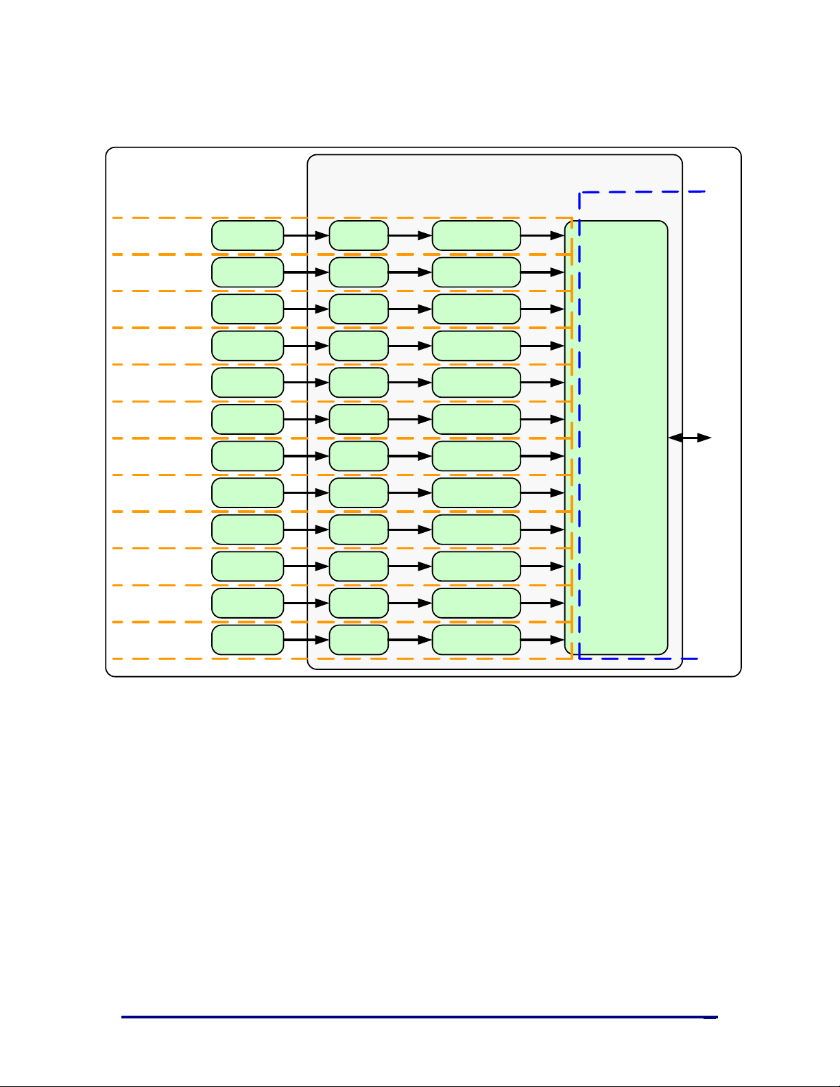
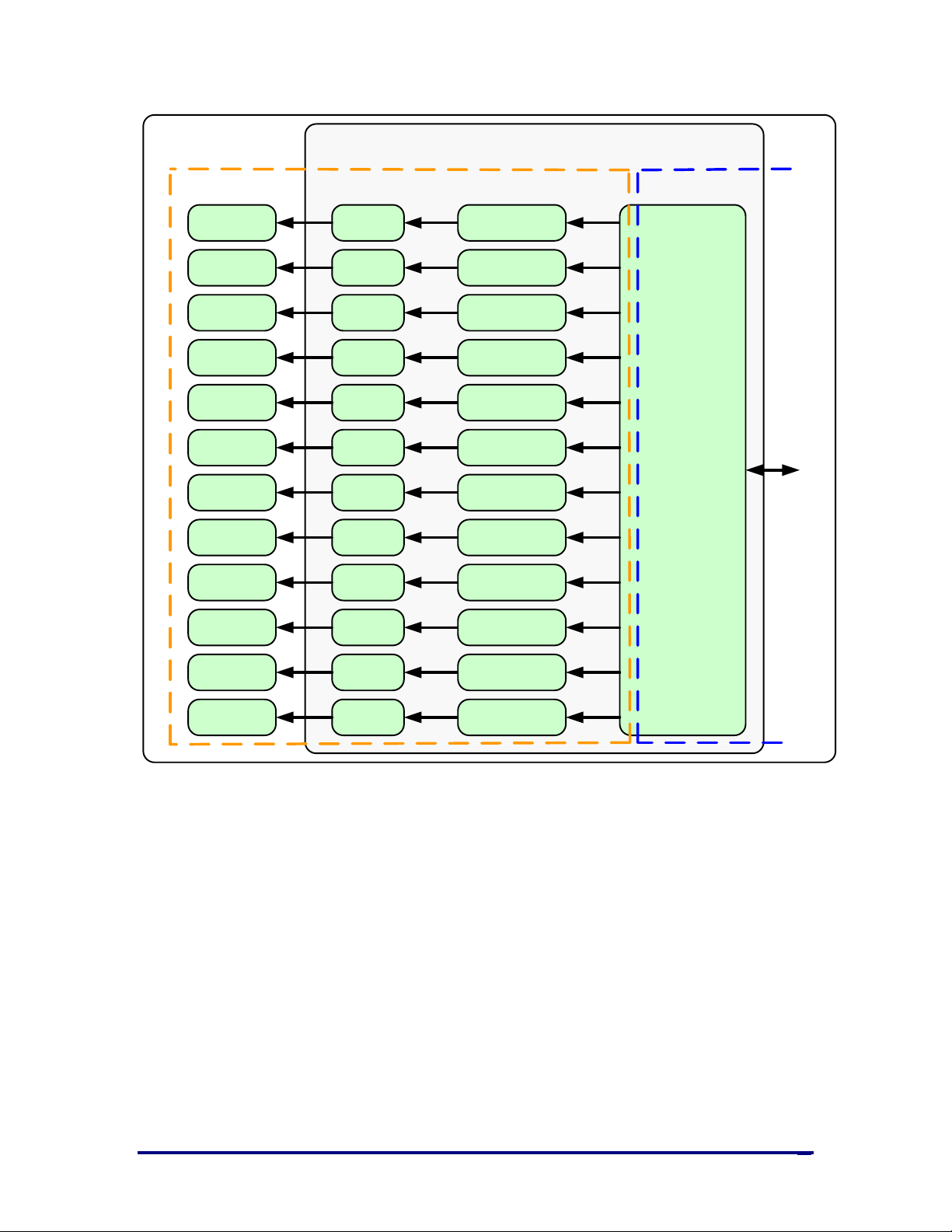
Figure 3 shows the different clock domains in the RX direction along with their associated clock
inputs. Figure 4 shows the different clock domains in the TX direction along with their associated
clock inputs. The IIPC handles all clock domain crossings.
UG032, May 15, 2014
12
Page 13
hs
_if
per_lane_
rx
rx
_destriping
clk
serDes
IIPC Core
hs_
if
per
_
lane
_
rx
serDes
hs
_
if
per_lane_rx
serDes
hs_if
per
_lane
_
rx
serDes
hs
_
if
per_
lane_rx
serDes
hs_if
per
_lane_
rx
serDes
hs_
if
per_lane
_rx
serDes
hs_if
per
_lane_
rx
serDes
hs_
if
per
_lane
_
rx
serDes
hs_
if
per
_lane_rx
serDes
hs_if
per_
lane_rx
serDes
hs_
if
per
_lane_rx
serDes
Interface to user logic in the FPGA Core
rx_serdes_clk[0]
rx_
serdes
_clk
[
1
]
rx_serdes_clk[2]
rx
_
serdes_
clk[
3
]
rx
_serdes_
clk[
4]
rx
_serdes_
clk[
5]
rx
_serdes_
clk[6
]
rx
_serdes_
clk[7]
rx_
serdes
_clk[
8]
rx
_serdes
_clk
[9]
rx
_serdes
_
clk[10]
rx
_
serdes_
clk[11
]
Figure 3: RX Clock Domains
UG032, May 15, 2014
13
Page 14
hs_if per_lane
_tx
tx_striping
clktx_serdes_refclk
serDes
IIPC Core
hs_if
per_lane_txserDes
hs_if
per_lane_tx
serDes
hs_if per_lane_tx
serDes
hs_if per_lane_txserDes
hs_if per_lane_tx
serDes
hs_if
per_lane_tx
serDes
hs_if
per_lane_tx
serDes
hs_if
per_lane_txserDes
hs_if per_lane_tx
serDes
hs_if per_lane_txserDes
hs_if
per_lane_tx
serDes
Interface to user logic in the FPGA Core
Figure 4: TX Clock Domains
UG032, May 15, 2014
14
Page 15

Port List
synchronized to the positive edge of the
Table 1 shows the port list for the IIPC. More detail on the use of each signal is given in the User
Interfaces section.
Table 1 – Port Description
Name Direction Clock Description
Register Interface
sbus_req
sbus_datain[1:0]
sbus_ack
sbus_dataout[1:0]
rx_serdes_data[19:0
]
Input sbus_clk
Input sbus_clk
Output sbus_clk
Output sbus_clk
Transceiver I/O
Input rx_serdes_clk
Asserted for 9-cycles in case of read and for
11-cycles in case of write
Carries read/write indication, address and
data to write
Acknowledgment from register i/f once
read or write is completed thru SBUS.
During write it is valid for one cycle to
indicate the end of the transfer. This is
asserted for 4-cycles to validate 8-bit data at
the end of read.
Contains read data for 4-cycles when
o_sbus_ack is asserted.
Data bus from the SerDes. There are 12
rx_serdes_data buses; one bus for each
SerDes lane and each bus has 20 bits.
By definition, bit [19] is the first bit received
by the IIPC. Bit [0] is the last bit received.
tx_serdes_data[19:0]
rx_serdes_clk[11:0] Input
UG032, May 15, 2014
Output
tx_serdes_ref
clk
Data bus to the SerDes . There are 12
tx_serdes_data buses; one bus for each
SerDes lane and each bus has 20 bits.
By definition, bit [19] is the first bit
transmitted by the IIPC. Bit [0] is the last bit
transmitted.
Recovered clock of each SerDes lane. The
rx_serdes_data bus for each lane
15
Page 16

Name Direction Clock Description
corresponding bit of this bus.
rx_serdes_resetn[11:
0]
Input
Reset for each RX SerDes lane. The
recovered clock for each SerDes lane has
associated with it an active-low reset. This
signal is low until transmit and receive
data-paths of each SerDes are ready.
tx_serdes_refclk Input
tx_serdes_refclk_res
etn
Input
LBUS Interface – Clock/Reset Signals
clk Input
rx_resetn Input
Common clock for the all Tx SerDes
interfaces.
Active low reset for TX Reference clock.
This signal is low until the PLL in the
SerDes is locked and the transmit data-path
is ready in lane #0.
Local bus clock. All signals between the
IIPC and the user side logic are
synchronized to the positive edge of this
signal.
Asynchronous reset for the RX circuits.
This signal is active low (0 = reset). Initially
this reset is applied from the board.
Subsequently it can be applied by the user
dynamically or based on the readiness of
SerDes receive and transmit paths. The
IIPC handles synchronizing the rx_resetn
input to the appropriate clock domains
within the IIPC.
tx_resetn Input
rx_dataout[511:0] Output clk
rx_chanout[7:0] Output clk
UG032, May 15, 2014
Asynchronous reset for the TX circuits. This
signal is active low (0 = reset). Initially this
reset is applied from the board.
Subsequently it can be applied by the user
dynamically or based on the readiness of
SerDes PLL and transmit path. The IIPC
handles synchronizing the tx_resetn input
to the appropriate clock domains within the
IIPC.
LBUS Interface – RX Path Signals
Receive LBUS Data. The value of the bus is
only valid in cycles that rx_enaout is
sampled as 1.
Receive Channel Number. The bus
16
Page 17

Name Direction Clock Description
indicates the channel number of the in-
rx_enaout Output clk
flight packet and is only valid in cycles that
rx_enaout is sampled as 1.
Receive LBUS Enable. This signal qualifies
the other signal of the RX LBUS Interface.
Signals of the RX LBUS Interface are only
valid in cycles that rx_enaout is sampled as
a 1.
rx_sopout
clk
Output
rx_eopout Output clk
rx_errout Output clk
rx_mtyout[5:0] Output clk
Receive LBUS Start-Of-Packet. This signal
indicates the Start Of Packet (SOP) when it
is sampled as a 1 and is only valid in cycles
that rx_enaout is sampled as a 1.
Receive LBUS End-Of-Packet. This signal
indicates the End Of Packet (EOP) when it
is sampled as a 1 and is only valid in cycles
that rx_enaout is sampled as a 1.
Receive LBUS Error. This signal indicates
that the current packet being received has
an error when it is sampled as a 1. This
signal is only valid in cycles when both
rx_enaout and rx_eopout are sampled as a
1. When this signal is a value of 0, it
indicates that there is no error in the packet
being received.
Receive LBUS Empty. This bus indicates
how many bytes of the rx_dataout bus are
empty or invalid for the last transfer of the
current packet. This bus is only valid in
cycles when both rx_enaout and rx_eopout
are sampled as 1.
tx_rdyout Output clk
UG032, May 15, 2014
When rx_errout and rx_enaout are sampled
as 1, the value of rx_mtyout[2:0] is always
000. Other bits of rx_mtyout are as usual.
LBUS Interface – TX Path Signals
Transmit LBUS Ready. This signal indicates
whether the IIPC TX path is ready to accept
data and provides back-pressure to the user
logic. A value of 1 means the user logic can
pass data to the IIPC. A value of 0 means
the user logic must stop transferring data to
the IIPC. tx_rdyout is de-asserted when last
16-locations are available in the FIFO.
17
Page 18

Name Direction Clock Description
sampled only in cycles that tx_enain and
tx_ovfout Output clk
tx_datain[511:0] Input clk
tx_chanin[7:0] Input clk
tx_enain Input clk
Transmit LBUS Overflow. This signal
indicates whether the user has violated the
back pressure mechanism provided by the
tx_rdyout signal. If tx_ovfout is sampled as
a 1, a violation has occurred. It is up to the
user to design the rest of the user logic in
order to not overflow the TX interface.
Transmit LBUS Data. This bus receives
input data from the user logic. The value of
the bus is captured in every cycle that
tx_enain is sampled as 1.
Transmit LBUS Channel Number. This bus
receives the channel number for the packet
being written. The value of the bus is
captured in every cycle that tx_enain is
sampled as 1.
Transmit LBUS Enable. This signal is used
to enable the TX LBUS Interface. All signals
on this interface are sampled only in cycles
that tx_enain is sampled as a 1.
tx_sopin Input clk
tx_eopin Input clk
tx_errin Input clk
tx_mtyin[5:0] Input clk
Transmit LBUS Start-Of-Packet. This signal
is used to indicate the Start Of Packet (SOP)
when it is sampled as a 1 and is 0 for all
other transfers of the packet. This signal is
sampled only in cycles that tx_enain is
sampled as a 1.
Transmit LBUS End-Of-Packet. This signal
is used to indicate the End Of Packet (EOP)
when it is sampled as a 1 and is 0 for all
other transfers of the packet. This signal is
sampled only in cycles that tx_enain is
sampled as a 1.
Transmit LBUS Error. This signal is used to
indicate a packet contains an error when it
is sampled as a 1 and is 0 for all other
transfers of the packet. This signal is
sampled only in cycles that tx_enain and
tx_eopin are sampled as 1.
Transmit LBUS Empty. This bus is used to
indicate how many bytes of the tx_datain
bus are empty or invalid for the last
transfer of the current packet. This bus is
UG032, May 15, 2014
18
Page 19

Name Direction Clock Description
tx_eopin are sampled as 1.
value of 1, a burst (i.e. a sequence of Data
tx_bctlin Input clk
When tx_eopin and tx_errin are sampled as
1, the value of tx_mtyin[2:0] is ignored as if
it was 000. The other bits of tx_mtyin are
used as usual.
Transmit force insertion of Burst Control
word. This input is used to force the
insertion of a Burst Control Word. When
tx_bctlin and tx_enainare sampled as 1, a
Burst Control word is inserted before the
data on the tx_datain bus is transmitted
even if one is not required to observe the
ctl_tx_burstmax parameter.
This input is intended to be used by
external schedulers that wish to reduce
bandwidth lost due to observation of the
ctl_tx_burstshort parameter (see the Use of
tx_bctlin section for more details).
Use of this input is not a requirement for
correct IIPC operation.
LBUS Interface – TX Path Control/Status Signals
ctl_tx_fc_stat[255:0] Input clk
stat_tx_overflow_er
r
stat_tx_underflow_e
rr
Output clk
Output clk
TX In-Band Flow Control Input. These
signals are used to set the status for each
calendar position in the in-band-flow
control mechanism (see Interlaken Protocol
Definition). A value of 1 means XON, a
value of 0 means XOFF.
These bits are transmitted in the Interlaken
Control Word bits [55:48].
Tx overflow. This output should never be
asserted. It indicates a critical failure and
should be fixed.
TX Underflow. This signal indicates if the
LBUS interface is being clocked too slowly
to properly fill the link with data.
In normal operation, this signal will always
be sampled as 0.
If this signal is sampled as 1, the clocks are
not set to proper frequencies and must be
fixed.
stat_tx_burst_err Output clk
UG032, May 15, 2014
TX BurstShort Error. When this signal is a
19
Page 20

Name Direction Clock Description
Words between two Control Words) was
section 5.4.6 of Interlaken Protocol
stat_rx_burstmax_er
r
stat_rx_parity_err[1
2:0]
shorter than the value specified by
ctl_tx_burstshort. This signal is only asserted
if the final Control Word did not contain an
EOP. This signal is provided to identify
poor scheduler design by the user that will
result in reduced throughput. This signal is
informational only and may be optionally
ignored.
LBUS Interface – RX Path Control/Status Signals
RX BurstMax Error. When this signal is a
value of 1, a burst (i.e. a sequence of Data
Words between two Control Words) was
Output clk
detected that was longer than the value of
ctl_tx_burstmax programmed. This signal is
informational only and may be optionally
ignored.
This bus indicates parity error in the Rx.
Output clk
Bit[12] indicates parity error in the buffer
and rest all bits indicate parity error in
SerDes lane [11:0].
stat_rx_diagword_l
anestat
[11:0]
stat_rx_diagword_i
ntfstat
[11:0]
stat_rx_crc32_valid[
11:0]
Output clk
Output clk
Output clk
Lane Status messaging outputs. This bus
reflects the most recent value in bit 33 of
the Diagnostic Word received on the
respective lane. These bits should only be
considered valid if the respective bit in
stat_rx_crc32_valid is a value of 1. See
Appendix A in Interlaken Protocol
Definition rev1.2.
Lane Status messaging outputs. This bus
reflects the most recent value in bit 32 of
the Diagnostic Word received on the
respective lane. These bits should only be
considered valid if the respective bit in
stat_rx_crc32_valid is a value of 1. See
Appendix A in Interlaken Protocol
Definition rev1.2.
Diagnostic Word CRC32 Valid. This bus
reflects the validity of the CRC32 in the
most recently received Diagnostic Word for
the respective lane. A value of 1 indicated
the CRC32 was valid and a value of 0
indicated the CRC32 was invalid. See
UG032, May 15, 2014
20
Page 21

Name Direction Clock Description
Definition rev1.2.
indicates whether all lanes are aligned and
stat_rx_crc32_err[11
:0]
Output clk
stat_rx_mubits[7:0] Output clk
stat_rx_synced[11:0] Output clk
stat_rx_synced_err[
11:0]
Output clk
Diagnostic Word CRC32 Error/Invalid. This
bus provides indication of an invalid
CRC32 in the Diagnostic Word for the
respective lane. These signals are asserted
with a value of 1 for one LBUS clock cycle
each time an error is detected.
RX Multiple-Use Control Bits. This bus
contains the “Multi-Use” field of the
Interlaken Control (see Interlaken Protocol
Definition). The value of the bus are
bits[31:24] of the most recently received
Interlaken Control Word.
Word Boundary Synchronized. These
signals indicate whether a lane is word
boundary synchronized. A value of 1
indicates the corresponding lane has
achieved word boundary synchronization.
Word Boundary Synchronization Error.
These signals indicate whether an error
occurred during word boundary
synchronization in the respective lane. A
value of 1 indicates the corresponding lane
had a word boundary synchronization
error.
Meta Frame Length Error. These signals
stat_rx_mf_len_err[
11:0]
Output clk
indicate whether a Meta Frame length
mismatch occurred in the respective lane. A
value of 1 indicates the corresponding lane
is receiving Meta Frame of wrong length.
Meta Frame Consecutive Error. These
stat_rx_mf_repeat_e
rr
[11:0]
Output clk
signals indicate whether consecutive Meta
Frame errors occurred in the respective
lane. A value of 1 indicates an error in the
corresponding lane.
Scrambler State Control Word Error. These
stat_rx_descram_err
Output clk
[11:0]
signals indicate a mismatch between the
received Scrambler State Word and the
expected value. A value of 1 indicates an
error in the corresponding lane.
stat_rx_aligned Output clk
UG032, May 15, 2014
All Lanes Aligned/De-Skewed. This signal
21
Page 22

Name Direction Clock Description
de-skewed. A value of 1 indicates all lanes
the lane aligner did not receive the
stat_rx_aligned_err Output clk
stat_rx_crc24_err Output clk
stat_rx_overflow_er
r
Output clk
are aligned and de-skewed. When this
signal is a 1, the RX path is aligned and can
receive packet data.
Loss of Lane Alignment/De-Skew. This
signal indicates an error occurred during
lane alignment or lane alignment was lost.
A value of 1 indicates an error occurred.
Control Word CRC24 Error. This signal
indicates whether a mismatch occurred
between the received and the expected
CRC24 value. A value of 1 indicates a
mismatch occurred.
RX FIFO Overflow Error. This signal
indicates if the LBUS interface is being
clocked too slowly to properly receive the
data being transmitted across the link. A
value of 1 indicates an error occurred.
In normal operation, this signal will
always be sampled as 0. If this signal is
sampled as 1, the clocks are not set to
proper frequencies and must be fixed.
stat_rx_mf_err[11:0] Output clk
stat_rx_framing_err
[11:0]
Output clk
stat_rx_msop_err Output clk
stat_rx_meop_err Output clk
stat_rx_burst_err Output clk
stat_rx_misaligned Output clk
Meta Frame Synchronization Word Error.
These signals indicate that an incorrectly
formed Meta Frame Synchronization Word
was detected in the respective lane. A value
of 1 indicates an error occurred.
Framing Error. These signals indicate that
an illegal framing pattern was detected in
the respective lane. A value of 1 indicates
an error occurred.
Missing Start-of-Packet (SOP) Error. This
signal indicates that a Missing Start-ofPacket was detected (and corrected).
Missing End-of-Packet (EOP) Error. This
signal indicates that a Missing End-ofPacket was detected (and corrected).
This signal indicates that a BurstShort or a
burst length error was detected.
Alignment Error. This signal indicates that
UG032, May 15, 2014
22
Page 23

Name Direction Clock Description
expected Meta Frame Synchronization
stat_rx_bad_type_er
r[11:0]
Output clk
Word across all (active) lanes. This signal
can be used to collect the statistic
“RX_Alignment_Error" as described in
Table 5-9 of the Interlaken Protocol
Definition rev1.2. This signal is not asserted
until the Meta Frame Synchronization
Word has been received at least once across
all lanes. A value of 1 indicates the error
occurred.
Unexpected or Illegal Meta Frame Control
Word Block Type. These signals indicate an
unexpected or illegal Meta Frame Control
Word Block Type was detected. These
signals can be used to collect the statistic
"RX_Bad_Control_Error" as described in
Table 5-9 of the Interlaken Protocol
Definition rev1.2. A value of 1 indicates an
error in the corresponding lane.
UG032, May 15, 2014
23
Page 24

User Interfaces
The IIPC handles the intricate details of transporting data over an Interlaken link. The user
interface is a simple packet interface designed to allow the user to easily integrate the IIPC into a
system.
The LBUS consists of three separate interfaces:
1. Transmitter (TX) interface
2. Receiver (RX) interface
3. Status/Control interface
4. Register interface
The Transmitter accepts packet oriented data, packages the data in accordance with the
Interlaken Protocol Definition, and sends that packaged data to the SerDes. The Transmitter has
control/configuration inputs to shape the data packaging to meet specific user requirements.
The Receiver accepts Interlaken bit streams from the SerDes, removes the Interlaken packaging,
and provides packet oriented data to the user.
The Status/Control interface is used to set the characteristics of the interface and to monitor its
operation.
The register interface programs various Interlaken features as well parameters. Refer to the list of
all registers under this section.
The rest of this section describes the various LBUS interfaces and gives a detailed description of
each individual port. In the description below, the term asserting is used to mean “assigning a
value of 1,” and the term negating is used to mean “assigning a value of 0.”
UG032, May 15, 2014
24
Page 25

TX LBUS Interface
63
63
The synchronous TX Local bus interface accepts packet oriented data of arbitrary length. It
accepts data in either packet mode, or segment mode. All signals are synchronous relative to the
rising-edge of the clk port. Figure 5 shows a sample waveform for data transaction for a 257 byte
packet.
Figure 5: Sample TX Waveform with a 512-bit Data Bus
Data is written into the interface on every clock cycle when tx_enain is asserted. This signal
qualifies other inputs of the TX Local bus interface. This signal must be valid every clock cycle.
The start of a packet is identified by asserting tx_sopin with tx_enain. The end of a packet is
identified by asserting tx_eopin with tx_enain. Both tx_sopin and tx_eopin may be asserted at the
same cycle. This is done for packets that are less than or equal to the bus width.
The channel number for a packet is presented on the tx_chanin inputs and must be valid for
every cycle tx_enain is asserted. Once tx_sopin has been asserted with a certain channel number,
it may not be asserted again with that channel numbers until tx_eopin is asserted with the same
channel number.
Data is presented on tx_datain inputs. A 512-bit wide bus is used, with the first byte of the packet
is written on bits [511:504], the second byte on bits [503:496], and so forth.
During the last cycle of a packet tx_mtyin signals may be asserted. These signals indicate how
many byte lanes in the data bus are invalid (or empty). tx_mtyin signals only have meaning
during cycles when both tx_enain and tx_eopin are asserted.
If tx_mtyin has a value of 0x0, there are no empty byte lanes, or in other words, all bits of the data
bus are valid. If tx_mtyin has a value of 0x1, then 1 byte lane is empty, specifically bits [7:0] do
not contain valid data. If tx_mtyin has a value of 0x2, then 2 byte lanes are empty, specifically bits
[15:0] do not contain valid data. If tx_mtyin has a value of 0x3, then 3 byte lanes are empty,
specifically bits [23:0] do not contain valid data.
During the last cycle of a packet, when tx_eopin is asserted with tx_enain, tx_errin may also be
asserted. This marks the packet as being in error and this information is included in the final
Interlaken Control Word associated with this packet. When tx_eopin and tx_errin are sampled as
UG032, May 15, 2014
25
Page 26

1, the value of tx_mtyin[2:0] is ignored as if it was 000. The other bits of tx_mtyin are used as
usual.
Data can be safely written, i.e. tx_enain asserted, whenever tx_rdyout is asserted. After tx_rdyout
is negated, additional 16 writes, using tx_enain, can be safely performed provided tx_ovfout is
never asserted. Once tx_rdyout is asserted again, additional data can be written. If, at any time,
the back-pressure mechanism is violated, the tx_ovfout is asserted to indicate the violation.
Data Formatting
Interlaken segments packets into bursts as described in the Interlaken Protocol Definition rev 1.2 .
A burst is a sequence Data Word between two Control Words. The size of the bursts generated by
the IIPC is controlled by two factors:
1. Parameters ctl_tx_burstmax and ctl_tx_burstshort programmed in registers
2. How the user write packets into the TX
The IIPC operates in one of two modes, depending on how the user writes data into the TX:
1. Packet Mode
2. Segment Mode
Packet Mode
Packet mode simply means that a packet with a certain channel number is written in its entirety
without interruption by a packet for a different channel. The first data written for a packet begins
with tx_sopin asserted and the final write operation has tx_eopin asserted.
Unless tx_bctlin is asserted (see the Use of tx_bctlin section) the size of the bursts (i.e. the
number of Data Word between Control Words) will be ctl_tx_burstmax except for the last burst of
a packet which will be between ctl_tx_burstshortand ctl_tx_burstmax
Segment Mode
Segment mode simply means that packets with different channel addresses/identifiers may be
interleaved.
User’s tasks:
• Once tx_sopin has been asserted for a channel, do not assert again for that channel until a
corresponding tx_eopin for that channel has been written.
• Unless tx_eopin is asserted, provide valid data to the full width of the data bus (tx_datain) as
discussed in the TX LBUS Interface section above.
The size of the bursts generated in Segment mode is governed by the tx_bctlin input (see the Use
of tx_bctlin section), ctl_tx_burstshort, ctl_tx_burstmax, and the changing of the channel ID of
packets.
User’s tasks:
• It is strongly recommended to implement the Optional Scheduling Enhancement as
described in section 5.3.2.1.1 of the Interlaken Protocol Definition rev1.2 document to
maximize throughput.
UG032, May 15, 2014
26
Page 27

• It also strongly recommended that the changing of channels be such that the number of
bytes between Control Words, whether forced (via tx_bctlin) or implied, be a multiple of
ctl_tx_burstmax. Except for the last burst of a packet, no burst should ever be less than
ctl_tx_burstshort.
Use of tx_bctlin
The tx_bctlin input operates in a similar manner to tx_sopin: both signals cause a Burst Control
Word to be injected into the data stream.
The purpose of the tx_bctlin input is to permit the forcing of Burst Control Words that otherwise
would not be transmitted. This is a necessary function for the creation of an external scheduler
that implements the Optional Scheduling Enhancement described in section 5.3.2.1.1 of the
Interlaken Protocol Definition rev1.2.
The IIPC strictly observes the programmed values for ctl_tx_burstmax and ctl_tx_burstshort and
injects Burst and Idle Control Words where required. Consequently, the IIPC may inject Idle
Control Words, that otherwise would not be required and thereby reduce effective bandwidth.
User’s task:
• Ensure that all rules governing Interlaken bursts, as defined in the Interlaken Protocol
Definition Revision 1.2, are followed when using tx_bctlin.
UG032, May 15, 2014
27
Page 28

RX LBUS Interface
63
63
The synchronous RX Local bus interface provides packet oriented data much like the TX Local
bus interface accepts. All signals are synchronous with the rising-edge of the Local bus clock.
Figure 6 shows a sample waveform for data transaction for a 257 byte packet.
Figure 6: Sample RX Waveform with a 512-bit Data Bus
Data is supplied by the IIPC on every clk clock cycle when rx_enaout is asserted. This signal
qualifies the other outputs of the RX Local bus interface.
Similar to the TX Local bus interface, rx_sopout identifies the start of a packet and rx_eopout
identifies the end of a packet. Both rx_sopout and rx_eopout will be asserted during the same
cycle for packets that are less than or equal to the bus width.
The channel number for a packet is presented on the rx_chanout outputs and is valid during
every cycle rx_enaout is asserted.
Similar to the TX Local bus interface, the first byte of a packet is supplied on the most significant
bits of rx_dataout. For the 512-bit wide bus, the first byte of the packet is written on bits [511:504],
the second byte on bits [503:496], and so forth
Similar to the TX Local bus interface, portions of packets are written on the bus in the full width
of the bus unless rx_eopout is asserted. When rx_eopout is asserted, the rx_mtyout bus indicates
how many byte lanes in the data bus are invalid. The encoding is the same as for tx_mtyin.
During the last cycle of a packet, when rx_eopout is asserted with rx_enaout, rx_errout may also
be asserted. This indicates one of two things:
1. The packet was sent with the "error flag" set, or
2. An error, such as a CRC24 error, was detected sometime during the receipt of the packet.
When rx_errout is asserted the value of rx_mtyout[2:0] is always 000. The other bits of rx_mtyout
are as usual.
There is no mechanism to back pressure the RX Local bus interface.
User’s task:
UG032, May 15, 2014
28
Page 29

• The user logic must be capable of receiving data when rx_enaout is asserted, and use the
Interlaken flow control mechanism to stop the far device (the one sending data to the
IIPC) from sending more data if needed.
The data provided by the RX Local bus interface is in the same sequence as it is received from the
Interlaken bus. Packets may be interleaved and are distinguished using the channel number
presented on rx_chanout.
UG032, May 15, 2014
29
Page 30

Status/Control Interface
The Status/Control interface allows the user to setup the IIPC configuration and to monitor the
status of the IIPC directly. All these signals listed below are available to user directly. User can
decide how to use these signals. The following sections describe the various Status and Control
signals.
Note: Proper understanding of the status signals’ description below entails a solid understanding
of the Interlaken Protocol. Refer to the Interlaken Protocol Definitionrev1.2 document for more
details.
RX Meta Frame Status
The Interlaken protocol requires that each lane align/synchronize to incoming words using the
procedure described in the Interlaken Protocol Definition. The IIPC provides status bits to
indicate the state of word boundary synchronization and lane alignment. All signals are
synchronous with the rising-edge of clk and a detailed description of each signal follows.
stat_rx_synced[11:0]
When a bit of this bus is 0, it indicates that word boundary synchronization of the corresponding
lane is not completed or that an error has occurred as identified by another status bit.
When a bit of this bus is 1, it indicates that the corresponding lane is word boundary
synchronized and is receiving Meta Frame Synchronization Words and Scrambler State Control
Words as expected.
stat_rx_synced_err[11:0]
When a bit of this bus is 1, it indicates one of several possible failures on the corresponding lane:
• Word boundary synchronization in the lane was not possible using Framing bits [65:64]
• After word boundary synchronization in the lane was achieved, errors were detected on
Framing bits [65:64]
• After word boundary synchronization in the lane was achieved, a valid Meta Frame
Synchronization Word was never received
The bits of the bus remain asserted until word boundary synchronization occurs or until some
other error/failure is signaled for the corresponding lane.
stat_rx_mf_len_err[11:0]
When a bit of this bus is 1, it indicates that Meta Frame Synchronization Words are being
received but not at the expected rate in the corresponding lane. The transmitter and receiver must
be re-configured with the same Meta Frame length.
The bits of the bus remain asserted until word boundary synchronization occurs or until some
other error/failure is signaled for the corresponding lane.
stat_rx_mf_repeat_err[11:0]
After word boundary synchronization is achieved in a lane, if a bit of this bus is a 1, it indicates
one of the following:
UG032, May 15, 2014
30
Page 31

• Four consecutive invalid Meta Frame Synchronization Words were detected in the
corresponding lane, or
• Three consecutive invalid Scrambler State Control Words were detected in the
corresponding lane.
The bits of the bus remain asserted until word boundary synchronization occurs or until some
other error/failure is signaled for the corresponding lane.
stat_rx_descram_err[11:0]
When a bit of this bus is 1, it indicates that a Scrambler State Control Word with an unexpected
value was received on the corresponding lane. This bit is only asserted after word boundary
synchronization is achieved. This output is asserted for one clock period each time a descrambler
error is detected.
stat_rx_mf_err[11:0]
When a bit of this bus is 1, it indicates that an invalid Meta Frame Synchronization Word was
received on the corresponding lane. This bit is only asserted after word boundary
synchronization is achieved. This output is asserted for one clock period each time an invalid
Meta Frame Synchronization Word is detected.
stat_rx_aligned
When stat_rx_aligned is a value of 1, all of the lanes are aligned/de-skewed as explained in the
Interlaken Protocol Definition and the receiver is ready to receive packet data.
stat_rx_aligned_err
When stat_rx_aligned_err is a value of 1, one of two things occurred:
1. Lane alignment failed after several attempts, or
2. Lane alignment was lost (stat_rx_aligned was asserted and then it was negated).
stat_rx_framing_err[11:0]
When a bit of this bus is 1, an illegal framing pattern was detected on the corresponding lane
after word boundary synchronization. If this error is detected after lane alignment, the error is
treated like a CRC24 error (see the Error Handling section).
This output is asserted for one clock period each time an illegal framing pattern is detected.
RX Error Status
The IIPC provides status signals to identify Interlaken data transmission protocol violations in
sequences of Control and Data words. These are errors independent of the status of the Meta
Frame. Generally these signals do not indicate a failure on the part of the sending transmitter but
of some kind of corruption during the transmission.
All signals are synchronous with the rising-edge of clk and a detailed description of each signal
follows.
stat_rx_crc24_err
When this signal is a value of 1, it indicates that the error detection logic has identified a
mismatch between the expected and received value of CRC24 in a Control Word.
Every time a CRC24 error is detected, all open packets are marked as containing errors as
specified by the Interlaken ProtocolDefinition. By definition, there is no mechanism provided by
Interlaken to associate a CRC24 error with individual packets.
UG032, May 15, 2014
31
Page 32

This signal is asserted for one clock period each time a CRC24 error is detected.
stat_rx_msop_err
Packets received with a particular channel address must begin with a valid Start-of-Packet (SOP).
If data is detected for a particular channel without a valid SOP, this signal is asserted for a single
Local bus clock cycle. Additionally, the required SOP is inserted before the data and an error is
signaled in the End-of-Packet (EOP) cycle via the rx_errout signal.
This signal is available as a status signal to indicate a missing SOP error condition occurred. No
indication is provided on the Local bus which packet had the missing SOP. The packet is simply
marked as containing an error. This is because a missing SOP is almost always associated with
other errors that cannot be associated with a particular packet.
The purpose of SOP insertion is to ensure that packets for a particular channel are always
delivered on the RX Local bus with the beginning with an SOP and ending with an EOP to
remove the need for user logic to perform bus protocol checking. The stat_rx_msop_err status
signal indicates that this function is being performed and for most applications can be ignored.
stat_rx_meop_err
Packets received with a particular channel address must begin with a valid Start-of-Packet (SOP)
and end with a valid End-of-Packet (EOP). If an SOP is detected without receiving an EOP for the
previous packet, this signal is asserted for a single Local bus clock cycle. Additionally, the extra
SOP is deleted, the packets are merged together, and an error is signaled with the End-of-Packet
(EOP) via the rx_errout signal.
This signal is available as a status signal to indicate a missing EOP error condition occurred and
that SOP deletion occurred. No indication is provided on the Local bus which packet is actually a
merged packet. The packet is simply marked as containing an error. This is because a missing
EOP is almost always associated with other errors that cannot be associated with a particular
packet.
The purpose of SOP deletion is to ensure that packets for a particular channel are always
delivered on the RX Local bus with the beginning with an SOP and ending with an EOP to
remove the need for user logic to perform bus protocol checking. The stat_rx_meop_err status
signal indicates that this function is being performed and for most applications can be ignored.
stat_rx_burst_err
This signal is asserted if:
1. A BurstShort violation is detected, or
2. A burst length violation is detected.
When this signal is a value of 1, it indicates one of the above burst errors has been detected. These
errors are treated like a CRC24 error and all open packets are treated as being in error.
This signal is asserted for one clock period each time an error is detected.
A BurstShort error occurs when the spacing between Burst Control Words is less than the
ctl_tx_burstshort parameter. A burst length violation occurs when the length of a received burst,
other than those ending with an End-of-Packet, is not a multiple of the RX LBUS width.
UG032, May 15, 2014
32
Page 33

CRC32 Diagnostics Checkin g
Interlaken implements a CRC32 check for each lane of the interface in order for the user to
monitor the health of each lane. The IIPC has two signals for this function that are listed below.
All signals are synchronous with the rising-edge of clk.
stat_rx_crc32_valid[11:0]
When a bit of this bus is 1, it indicates two things:
1. The CRC32 in the most recently received Diagnostic Word on the corresponding lane
was valid, and
2. The corresponding lane is word boundary synchronized.
When this bit is a value of 0, it indicates that a CRC32 error was detected or the corresponding
lane is not word boundary synchronized.
stat_rx_crc32_err[11:0]
When a bit in this bus is 1, it indicates that after the corresponding lane was word boundary
synchronized, a CRC32 error was detected. This output is asserted for one clock period each time
a CRC32 error is detected.
Note: CRC32 errors do not affect word boundary synchronized. They are only reported as status
indicators. The user can keep a count of how many CRC32 errors were detected for each lane in
order to examine the health of each individual lane over a period of time.
Note: The checking of the Diagnostic Word does only checks the CRC32 and does not check
whether the unused bits of the Diagnostic Word, 57:34, are 0s as described in the Interlaken
Protocol Definition.
Interlaken Status Messagin g for the Receiv er
The Meta Frame Diagnostic words calculate a CRC32 over all the data within the Meta Frame in a
lane to help diagnose errors. The Interlaken protocol provides for optional status messaging
within these Diagnostic Words. This mechanism allows a Receiver to communicate, via the
adjacent Transmitter or an out-of-band flow control interface, the health of each (received) lane
and the overall health of the Receiver interface to the other device.
The results of received Diagnostic Words are described in the signals listed below. All signals are
synchronous with the rising-edge of clk.
stat_rx_diagword_intfstat[11:0]
Each bit of this bus reflects the value of bit[32], the interface health (Status Bit 0), in the most
recently received Diagnostic Word on the corresponding lane. The value of this bit should be
considered invalid and ignored if the corresponding bit in stat_rx_crc32_valid[11:0] is a value of
0.
stat_rx_diagword_lanestat[11:0]
Each bit of this bus reflects the value of bit[33], the lane health (Status Bit 1), in the most recently
received Diagnostic Word on the corresponding lane. The value of this bit should be considered
invalid and ignored if the corresponding bit in stat_rx_crc32_valid[11:0] is a value of 0.
UG032, May 15, 2014
33
Page 34

Interlaken Status Messaging for the Transmitter
The Transmitter is capable of inserting the Status Messaging as described in the Interlaken
Protocol into the Meta Frame Diagnostics words.
User’s task: Feed these inputs based on the health of the Receiver.
All signals are synchronous with the rising-edge of clk and a detailed description of each signal
follows.
ctl_tx_diagword_intfstat
This input is transmitted on bit[32], the interface health (Status Bit 0), of every Diagnostic Word
on all of the lanes. A value of 1 is defined to mean a healthy condition.
User’s task: Drive proper data for this input. In typical applications, the user should simply
connect this input to the stat_rx_aligned output of the Receiver block.
ctl_tx_diagword_lanestat[11:0]
Each bit of this bus is transmitted on bit[33], the lane health (Status Bit 1), of every Diagnostic
Word for the corresponding lane. A value of 1 is defined to mean a healthy condition.
User’s task: Drive proper data for this input. In typical applications, the user should simply
connect this input to the stat_rx_synced[11:0] output of the Receiver block.
Transmitter Multiple-Use Bi ts
Interlaken defines an eight bit field in each Control Word as “Multiple-Use” bits. These bits are
transmitted with every Control Word that is sent and can be used to transmit any information the
user needs. For example, one of the bits can be used to represent a link-level flow control status.
The IIPC provides a mechanism for the user to set these bits to any desired value. All signals are
synchronous with the rising-edge of clk and a detailed description of each signal follows.
ctl_tx_mubits[7:0]
These inputs control the information contained in bits [31:24] of the Control words generated by
the Transmitter. The value of ctl_tx_mubits[0] will appear in bit 24 of the next Control Word
generated by the TX. The value of ctl_tx_mubits[1] will appear in bit 25, and so forth.
Receiver Multiple-Use Bits
Similar to the Transmitter, the IIPC extracts the “Multiple-Use” field from every received Control
Word and outputs the information to the user.
User’s task: Interpreting the meaning of these bits.
All signals are synchronous with the rising-edge of clk and a detailed description of each signal
follows.
stat_rx_mubits[7:0]
These outputs contain the information in bits [31:24] of the Control words received by the
Receiver. The value of Control Word bit [24] appears on stat_rx_mubits[0]. The value of Control
Word bit [25] appears on stat_rx_mubits[1], and so forth.
UG032, May 15, 2014
34
Page 35

Transmitter Flow-Control Inputs
The IIPC implements the Interlaken in-band flow control mechanism. This mechanism
communicates XON/XOFF for different channels using the In-Band Flow Control bits of Control
words. Additionally, the Multiple-Use bits of Control Words may be used in a similar manner as
described in the Transmitter Multiple-Use Bits and Receiver Multiple-Use Bits sections.
Inside each Interlaken Control Word are 16 bits of In-Band Flow Control information, bits[55:40],
and a Reset Calendar bit, bit[56]. These bits are shared over the calendar length as described
below. The Interlaken Core has a calendar length of 256 and provides one transmit bit and one
receive bit for each calendar entry.
By definition, XON is represented by 1, and XOFF is represented by 0 for both the Transmitter
and the Receiver. All signals are synchronous with the rising-edge of clk and a detailed
description of each signal follows.
ctl_tx_fc_stat[255:0]
The user is given full flexibility to implement any mechanism to handle system wide flow
control. The IIPC Transmitter simply inputs the user supplied calendar information and packs it
into the Interlaken Control words and transmits it over the link. This mechanism allows the user
to take into account system wide parameters and optimize the buffering by implementing the
most optimum flow control mechanism.
The operation is as described in the Interlaken Protocol Definition. The first calendar entry,
ctl_tx_fc_stat[0], is sent in bit[55] of a Control Word with the Reset Calendar bit, bit[56], set to a
value of 1. The next calendar entry, ctl_tx_fc_stat[1], is sent in bit[54] of the same Control Word
and so on. The 17th calendar entry, ctl_tx_fc_stat[16], is sent in bit[55] the next Control Word that
has the Reset Calendar bit, bit[56], set to a value of 0, and so forth.
ctl_tx_fc_callen[3:0]
The flow control calendar length can be shorter than the maximum calendar length supported by
the IIPCwith the help of ctl_tx_fc_callen parameter. When ctl_tx_fc_callen is a value of 0, the
calendar length become 16 and only ctl_tx_fc_stat[15:0] are used. When ctl_tx_fc_callen is a value
of 1, the calendar length become 32 only ctl_tx_fc_stat[31:0] are used. And so forth. The valid
settings for calendar length are as follows:
• 0x0 = 16 entries
• 0x1 = 32 entries
• 0x3 = 64 entries
• 0x7 = 128 entries
• 0xF = 256 entries
All other values are reserved.
Note: This input should be static and must only be changed during reset.
UG032, May 15, 2014
35
Page 36

Register Interface
The register interface provides access to control and status registers for the IIPC. These registers
can be accessed via the FPGA’s SBus. IIPC is a slave on SBus. Users need to design the master
interface in the fabric to drive SBus. For information about the SBus, see
https://www.achronix.com/wpcontent/uploads/docs/Speedster22i_sBus_User_Guide_UG047.pdf.
Address Name Description
TX Decommissioning Register – R/W – Default: ‘h1717
0x0102 txdecomm
0x0104 txlanestat
0x0108 txintfstat
0x010A txrlimen
0x010C txrlimmax
Bits 4:0 – TX Last Lane (ctl_tx_last_lane)
Bits 12:8 TX Bad Lane (ctl_tx_has_bad_lane)
TX Lane Status Messaging Register – R/W
Setting Bit X to 1 sets Bit 33 in the Diagnostic Word for lane X
(ctl_tx_diagword_lanestat)
TX Interface Status Messaging Register – R/W
Setting bit 0 to a value of 1 sets bit 32 in the Diagnostic Word for each
lane (ctl_tx_diagword_intfstat)
TX Rate Limiter Enable Register – R/W
Setting bit 0 to a value of 1 enables the rate limiter. (ctl_tx_rlim_en)
TX Rate Limiter Max Tokens Register – R/W
Bits 11:0 specify how many tokens are to be added to the token
bucket after each interval. This value must be greater than 0. This
value should not be changed when the rate limiter is enabled.
(ctl_tx_rlim_max)
TX Rate Limiter Delta Register – R/W
0x010E txrlimdelta
Setting bits 11:0 specifies how many tokens are to be added to the
token bucket after each interval. This value must be greater than 0.
This value should not be changed when the rate limiter is enabled.
(ctl_tx_rlim_delta)
UG032, May 15, 2014
36
Page 37

TX Rate Limiter Update Interval Register – R/W
0x0110 txrlimintv
0x011C txmubits
0x0140 txcallen
0x0144 txmframelen
Bits 7:0 specify the interval, in Local bus clock cycles, that the token
bucket will be updated. It is recommended that this value be greater
than or equal to 8. This value should not be changed when the rate
limiter is enabled. (ctl_tx_rlim_intv)
TX Multi-Use Bits Register – R/W
Bits 7:0 Specify a value contained in bits 31-24 of subsequent Control
Words generated by the TX. (ctl_tx_mubits)
TX Flow Control Calendar Length Register – R/W
Bits 3:0 Specify the number of bits of in-band flow-control that are
actually used. The settings are as follows: if LEN = 0, then calendar
length = 16; if LEN = 1, then calendar length = 32; if LEN = 3, then
calendar length = 64; if LEN = 7, then calendar length = 128; if LEN =
15, then calendar length = 256; All other values are reserved.
(ctl_tx_fc_callen)
TX Meta Frame Length Register – R/W
Bits 15:0 should be set to -1 the desired length. Thus for a Meta Frame
of 2048, a value of 2047 should be used. This input is specified in
terms of the number of words or cycles minus one. For example, if set
to 2047, then a Metaframe sync word is sent every 2048 word
transfers on every lane. See section 5.4.3 of Interlaken spec 1.1.
TX Skip Word Disable Register – R/W
0x0146 txskip
Bit 0 – if set to a value of 1 will disable the generation of a skip word
after the scrambler state word.
TX Burst Parameters Register – R/W
Bits 1:0 Specifies the maximum number of Data Words between Burst
Control Words. See section 5.3.2 of Interlaken spec 1.1. The following
0x0148 txburst
values are defined: 00=64 bytes, 01=128 bytes, 10=192 bytes, 11=256
bytes. (ctl_tx_burstmax)
Bits 10:8 Specifies the minimum spacing between Burst Control
Words. The values are defined as follows: 000=32 bytes, 001=64 bytes,
010=96 bytes, etc. (ctl_tx_burstshort)
UG032, May 15, 2014
37
Page 38

TX Status Register – R/W
rxdecomm
rxmframelen
Bit 3: Set to a value of 1 if tx_ovfout is asserted on the TX LBUS. Write
1 to clear.
0x014A txstat
0x0202
0x0204
Bit 2: Set to a value of 1 if an overflow occurs. This bit should never
be set and indicates a critical failure. Write 1 to clear.
Bit 1: Set to a value of 1 if a burst, less than BurstShort, not ending
with an EOP, is written into the TX. Write 1 to clear.
Bit 0: Set to a value of 1 if the serial data rate is faster than the
maximum data rate on the Local bus. Write 1 to clear.
RX Lane Decommissioning Register – R/W – Default: ‘h1717
Bits 15 indicates RX Has Bad Lane (ctl_rx_has_bad_lane)
Bits 12:8 - Rx Bad Lane
Bits 4:0 - Rx Last Lane (ctl_rx_last_lane)
RX Meta Frame Length Register – R/W
This input should be -1 the desired length. Thus for a Meta Frame of
2048, a value of 2047 should be used. This input is specified in terms
of the number of words or cycles minus one. For example, if set to
2047, then a Metaframe sync word is sent every 2048 word transfers
on every lane. See section 5.4.3 of Interlaken Protocol Definition
rev1.2.
RX Burst Register – R/W – Default: ‘h0003
Bit 8 - Setting this bit to 1 changes the way the error handler report
errors. When this bit is a value of 0, it assumes packets are arriving
interwoven as segments. When this bit is a value of 1, it assumes
packets are arriving as complete packets. Use of this bit ensures that
0x0206 rxctrl
packets delivered to the Local bus had the appropriate SOP and EOP
pairing. (ctl_rx_packet_mode)
Bits 1:0 - Specifies the maximum number of Data Words between
Burst Control Words expected by the RX. The following values are
defined: 00=64 bytes, 01=128 bytes, 10=192 bytes, 11=256 bytes.
(ctl_rx_burstmax)
UG032, May 15, 2014
38
Page 39

0x0210
to
0x022E
rxfcstat0-15
RX In-band Flow Control Registers (0-15) - RO
Provides the most recent value for in-band flow control for lanes 0-
255.
Register at 0x0210 – Bit 0 = Lane 0, Bit 15 = lane 15
Register at 0x0212 – Bit 0 = Lane 16, Bit 15 = lane 31
Continues Up to 0x22E where Bit 0 = lane 240 and Bit 15 = lane 255
RX Status Register – R/W
Bit 8 – When 1, RX CRC24 error was detected. Write 1 to clear.
Bit 7 – When 1, RX Burst error was detected. Write 1 to clear.
Bit 6 – When 1, RX BurstMax error was detected. Write 1 to clear.
Bit 5 – When 1, Missing RX Overflow was detected. Write 1 to clear.
0x0232 rxstat
0x0800
to
0x082E
statistics
counters
Bit 4 - When 1, Missing EOP was detected. Write 1 to clear.
Bit 3 – When 1, Missing SOP was detected. Write 1 to clear.
Bit 2 – When 1, Meta Frame Sync Word was not detected on all lanes.
Write 1 to clear.
Bit 1 – When 1, lane alignment was lost. Write 1 to clear.
Bit 0 – When 1, all lanes are aligned.
RX CRC32 Valid Statistics Registers – RO
0x0800 Bit 15:0 – returns the value contained in bits 15-0 (LSB) of RX
CRC32 Valid Statistics register for lane 0
0x0802 Bit 15:0 – returns the value contained in bits 31-16 (MSB) of
RX CRC32 Valid Statistics register for lane 0
0x0804 Bit 15:0 – returns the value contained in bits 15-0 (LSB) of RX
CRC32 Valid Statistics register for lane 1
0x0806 Bit 15:0 – returns the value contained in bits 31-16 (MSB) of
RX CRC32 Valid Statistics register for lane 1
Continues for all 12 lanes (0-11) up to address 0x082E
UG032, May 15, 2014
39
Page 40

0x0880
to
0x08AE
0x0900
to
0x092E
statistics
counters
statistics
counters
RX CRC32 Error Statistics Registers – RO
0x0880 Bit 15:0 – returns the value contained in bits 15-0 (LSB) of RX
CRC32 Error Statistics register for lane 0
0x0882 Bit 15:0 – returns the value contained in bits 31-16 (MSB) of
RX CRC32 Error Statistics register for lane 0
0x0884 Bit 15:0 – returns the value contained in bits 15-0 (LSB) of RX
CRC32 Error LSB Statistics register for lane 1
0x0886 Bit 15:0 – returns the value contained in bits 31-16 (MSB) of
RX CRC32 Error Statistics register for lane 1
Continues for all 12 lanes (0-11) up to address 0x08AE
RX Word Boundary Synchronization Statistics Registers – RO
0x0900 Bit 15:0 – returns the value contained in bits 15-0 (LSB) of RX
Word Boundary Synchronization Statistics register for lane 0
0x0902 Bit 15:0 – returns the value contained in bits 31-16 (MSB) of
RX Word Boundary Synchronization Statistics register for lane 0
0x0904 Bit 15:0 – returns the value contained in bits 15-0 (LSB) of RX
Word Boundary Synchronization Statistics register for lane 1
0x0906 Bit 15:0 – returns the value contained in bits 31-16 (MSB) of
RX Word Boundary Synchronization Statistics register for lane 1
Continues for all 12 lanes (0-11) up to address 0x092E
UG032, May 15, 2014
40
Page 41

0x0980
to
0x09AE
statistics
counters
RX Word Boundary Synchronization Error Statistics Registers – RO
0x0980 Bit 15:0 – returns the value contained in bits 15-0 (LSB) of RX
Word Boundary Synchronization Error Statistics register for lane 0
0x0982 Bit 15:0 – returns the value contained in bits 31-16 (MSB) of
RX Word Boundary Synchronization Error Statistics register for lane
0
0x0984 Bit 15:0 – returns the value contained in bits 15-0 (LSB) of RX
Word Boundary Synchronization Error Statistics register for lane 1
0x0986 Bit 15:0 – returns the value contained in bits 31-16 (MSB) of
RX Word Boundary Error Synchronization Statistics register for lane
1
Continues for all 12 lanes (0-11) up to address 0x09AE
0x0A00
to
0x0A2E
statistics
counters
RX Framing Error Statistics Registers – RO
0x0A00 Bit 15:0 – returns the value contained in bits 15-0 (LSB) of RX
Framing Error Statistics register for lane 0
0x0A02 Bit 15:0 – returns the value contained in bits 31-16 (MSB) of
RX Framing Error Statistics register for lane 0
0x0A04 Bit 15:0 – returns the value contained in bits 15-0 (LSB) of RX
Framing Error Statistics register for lane 1
0x0A06 Bit 15:0 – returns the value contained in bits 31-16 (MSB) of
RX Framing Error Statistics register for lane 1
Continues for all 12 lanes (0-11) up to address 0x0A2E
UG032, May 15, 2014
41
Page 42

0x0A80
to
0x0AAE
statistics
counters
RX Bad Type Error Statistics Registers – RO
0x0A80 Bit 15:0 – returns the value contained in bits 15-0 (LSB) of RX
Bad Type Error Statistics register for lane 0
0x0A82 Bit 15:0 – returns the value contained in bits 31-16 (MSB) of
RX Bad Type Error Statistics register for lane 0
0x0A84 Bit 15:0 – returns the value contained in bits 15-0 (LSB) of RX
Bad Type Error Statistics register for lane 1
0x0A86 Bit 15:0 – returns the value contained in bits 31-16 (MSB) of
RX Bad Type Error Statistics register for lane 1
Continues for all 12 lanes (0-11) up to address 0x0AAE
0x0B00
to
0x0B2E
statistics
counters
RX Bad Meta Frame Error Statistics Registers – RO
0x0B00 Bit 15:0 – returns the value contained in bits 15-0 (LSB) of RX
Bad Meta Frame Error Statistics register for lane 0
0x0B02 Bit 15:0 – returns the value contained in bits 31-16 (MSB) of
RX Bad Meta Frame Error Statistics register for lane 0
0x0B04 Bit 15:0 – returns the value contained in bits 15-0 (LSB) of RX
Bad Meta Frame Error Statistics register for lane 1
0x0B06 Bit 15:0 – returns the value contained in bits 31-16 (MSB) of
RX Bad Meta Frame Error Statistics register for lane 1
Continues for all 12 lanes (0-11) up to address 0x0B2E
UG032, May 15, 2014
42
Page 43

0x0B80
to
0x0BAE
statistics
counters
RX Meta Frame Length Error Statistics Registers – RO
0x0B80 Bit 15:0 – returns the value contained in bits 15-0 (LSB) of RX
Meta Frame Length Error Statistics register for lane 0
0x0B82 Bit 15:0 – returns the value contained in bits 31-16 (MSB) of
RX Meta Frame Length Error Statistics register for lane 0
0x0B84 Bit 15:0 – returns the value contained in bits 15-0 (LSB) of RX
Meta Frame Length Error Statistics register for lane 1
0x0B86 Bit 15:0 – returns the value contained in bits 31-16 (MSB) of
RX Meta Frame Length Error Statistics register for lane 1
Continues for all 12 lanes (0-11) up to address 0x0BAE
0x0C00
to
0x0C2E
statistics
counters
RX Meta Frame Repeat Error Statistics Registers – RO
0x0C00 Bit 15:0 – returns the value contained in bits 15-0 (LSB) of RX
Meta Frame Repeat Error Statistics register for lane 0
0x0C02 Bit 15:0 – returns the value contained in bits 31-16 (MSB) of
RX Meta Frame Repeat Error Statistics register for lane 0
0x0C04 Bit 15:0 – returns the value contained in bits 15-0 (LSB) of RX
Meta Frame Repeat Error Statistics register for lane 1
0x0C06 Bit 15:0 – returns the value contained in bits 31-16 (MSB) of
RX Meta Frame Repeat Error Statistics register for lane 1
Continues for all 12 lanes (0-11) up to address 0x0C2E
UG032, May 15, 2014
43
Page 44

0x0C80
to
0x0CAE
statistics
counters
RX Descrambler Error Statistics Registers – RO
0x0C80 Bit 15:0 – returns the value contained in bits 15-0 (LSB) of RX
Descrambler Error Statistics register for lane 0
0x0C82 Bit 15:0 – returns the value contained in bits 31-16 (MSB) of
RX Descrambler Error Statistics register for lane 0
0x0C84 Bit 15:0 – returns the value contained in bits 15-0 (LSB) of RX
Descrambler Error Statistics register for lane 1
0x0C86 Bit 15:0 – returns the value contained in bits 31-16 (MSB) of
RX Descrambler Error Statistics register for lane 1
Continues for all 12 lanes (0-11) up to address 0x0CAE
0x1000
to
0x17FE
statistics
counters
RX Channel Good/Bad Packet Count Registers – RO
0x1000 Bit 15:0 – returns the value contained in bits 15-0 (LSB) of RX
Channel 0 Good Packet Count
0x1002 Bit 15:0 – returns the value contained in bits 31-16 (MSB) of
RX Channel 0 Good Packet Count
0x1004 Bit 15:0 – returns the value contained in bits 15-0 (LSB) of RX
Channel 0 Bad Packet Count
0x1006 Bit 15:0 – returns the value contained in bits 31-16 (MSB) of
RX Channel 0 Bad Packet Count
0x1008 Bit 15:0 – returns the value contained in bits 15-0 (LSB) of RX
Channel 1 Good Packet Count
0x100A Bit 15:0 – returns the value contained in bits 31-16 (MSB) of
RX Channel 1 Good Packet Count
0x100C Bit 15:0 – returns the value contained in bits 15-0 (LSB) of RX
Channel 1 Bad Packet Count
0x100E Bit 15:0 – returns the value contained in bits 31-16 (MSB) of
RX Channel 1 Bad Packet Count
Continues for all 256 Channels (0-255) up to address 0x17FE
The Default value of all registers is ‘h00.
UG032, May 15, 2014
44
Page 45

Description of Features
Lane Decommission
The IIPC features two different modes of lane decommissioning:
1. Disabling consecutive lanes, and
2. Disabling a single lane.
Disabling consecutive lanes allows the same instantiation of the IP to be used for multiple
configurations. Disabling a single lane enables lane resiliency where one lane with too many
errors can be disabled in the same physical link. Both modes of decommissioning can be used at
the same time.
There are separate decommissioning controls for the RX and TX paths to allow system designers
to optimize performance by creating asymmetric links. The operation is similar for both RX and
TX paths and is described below.
Disabling Consecutive Lanes
Consecutive Transmit Lanes
Disabling consecutive transmit lanes is achieved by simply setting the ctl_tx_last_lane parameter
to the number of the last active SerDes lane. For example, for an 8 serial lane Interlaken link,
ctl_tx_last_lane would normally be set to a value of 7 since the lanes are numbered 0 to 7. If only 4
lanes are required, ctl_tx_last_lane should be assigned a value of 3. This causes the corresponding
path to only use lanes 0 to 3.
The minimum value for the last lane is dependent on the internal configuration of the core.
The value of ctl_tx_last_lane must only be changed when the TX path is held in reset.
Consecutive Receive Lanes
Disabling consecutive receive lanes is identical to disabling consecutive transmit lanes except the
ctl_rx_last_lane parameter is used instead.
UG032, May 15, 2014
45
Page 46

Disabling a Single Lane
Single Transmit Lane
To disable one of the lanes in the range between 0 to ctl_tx_last_lane, the parameters
ctl_tx_has_bad_lane and ctl_tx_bad_lane are used. To enable single lane decommissioning,
ctl_tx_has_bad_lane is set to 1, and the ctl_tx_last_lane is set to the number of the SerDes lane that
is decommissioned.
For example, in an 8 lane configuration where only six lanes are active (lanes 0 to 5), to disable
lane 3, the control signals are set as follows:
• ctl_tx_last_lane = 5
• ctl_tx_has_bad_lane = 1
• ctl_tx_bad_lane = 3
The value of ctl_tx_last_lane, ctl_tx_has_bad_lane and ctl_tx_bad_lane must only be changed when
the corresponding path is held in reset.
Single Receive Lane
Disabling a single receive lane is identical to disabling a single transmit lane except the
ctl_rx_last_lane and ctl_rx_has_bad_lane inputs are used instead.
UG032, May 15, 2014
46
Page 47

Link Level Flow Control
The Interlaken Protocol does not restrict the use of the calendar entries to a particular flow
control implementation. As such, the user can decide if one or more of the calendar entries
should be designated to control the flow control of the whole interface (i.e. link level flow
control). For example, if the calendar length is 32, the user can decide to use calendar slots 0 and
16 as link level flow control bits. This would result in transmitting the link level information with
every burst control word.
The IIPC implements the in-band flow control mechanism as described in the Interlaken Protocol
Definition. The IIPC is configured to have a fixed calendar length, and the TX and RX interfaces
are described in the Transmitter Flow-Control Inputs and Receiver Flow-Control Outputs
Bits sections.
User’s task: Connect the link level flow control information to the appropriate input pins of the
RX interface, and interpret the appropriate output pins of the TX interface.
UG032, May 15, 2014
47
Page 48

TX Rate Limiting
The IIPC rate limiter can be used to reduce the overall Data Word transmission rate. This is
achieved by transmitting Idle Control Words in between packet segments to limit the effective
data transfer rate. The purpose of transmitter rate limiting is to reduce buffering requirements by
the receiving device and reduce the amount of flow control stalling that may otherwise be
required.
Rate limiting is not a substitute for flow-control but something that should be used in conjunction
with flow-control when a receiver cannot continuously accept Data Words at the full rate. The
rate limiter uses a token bucket scheme. A token represents a single byte. When the token bucket
contains at least ctl_tx_burstmax number of tokens, up to ctl_tx_burstmax bytes are sent. Once
that has completed, the transmitter waits until there are at least ctl_tx_burstmax x number of
tokens in the bucket again before sending more data. The token count will go negative if it is
necessary to send a burst of data that cannot be interrupted.
The token bucket is refilled at a specified interval with some number of tokens. This interval is
specified in terms of Local bus clock cycles.
During each Local bus clock cycle, eight tokens are drained for each Interlaken Data Word that is
forwarded. This is true even for EOP Data Words that contain less than eight valid bytes.
A description of parameters that set the characteristics of the rate limiter is given below. All
signals are synchronous with the rising-edge of clk.
ctl_tx_rlim_enable
When this input is a value of 1, the rate limiter is enabled. When this input is a value of 0, the rate
limiter is disabled.
This input should only be changed from a 0 to a 1 after appropriate values have been put on
ctl_tx_rlim_enable, ctl_tx_rlim_max, ctl_tx_rlim_delta, ctl_tx_rlim_intv.
ctl_tx_rlim_max[11:0]
This input defines the maximum number of tokens in the bucket in terms of bytes (a value of 1,
means 1 byte). The number of tokens in the bucket will never exceed this value. This value must
be at least ctl_tx_burstmax. (For example, if ctl_tx_burstmax is set for 256 bytes, then this value
should be at least 256).
The value of this input should not be changed when ctl_tx_rlim_enable is a value of 1.
Note: The rates closest to the expected rates have been observed to be when ctl_tx_rlim_max is
set to a value between 1 and 2 times the value of BurstMax.
ctl_tx_rlim_delta[7:0]
This input specifies the update interval: the number of Local bus clock cycle between additions to
the token bucket. The value of this input should not be changed when ctl_tx_rlim_enable is a
value of 1.
Note: Values between 8 and 32 are recommended for this.
UG032, May 15, 2014
48
Page 49

ctl_tx_rlim_intv[11:0]
This input specifies how many tokens are to be added to the bucket after each interval. A token is
equal to 1 byte. This value must be greater than 0. The value of this input should not be changed
when ctl_tx_rlim_enable is a value of 1.
Note: This value should be calculated based on the desired rate and the value in ctl_tx_rlim_intv.
Example: Programming the Rate Limiter
Assuming the following:
• The Local bus clock frequency is 470 MHz
• BurstMax is 256 bytes
• The transmission rate is to be limited to 50 Gbits/s (or 6.25 Gbytes/s)
• The interval is arbitrarily chosen to be 8 Local bus clock cycles
The value for ctl_tx_rlim_delta is:
= (Byte Rate * Interval) / Local bus Frequency
= (6.25e9 Gb/sec * 8 cycles) * (1/470e6 sec)
= 106.4 bytes
The value for ctl_tx_rlim_max must be 256 or greater. Different values will result in different
shaping of traffic. Simulations must be done to select the proper value to get the desired packet
rate. For the above example ctl_tx_rlim_max could be 256.
UG032, May 15, 2014
49
Page 50

Error Handling
The IIPC performs robust checking of all possible error conditions as described in the Interlaken
Protocol Definition including the following errors:
• a loss of lane alignment,
• a CRC24 error,
• a BurstShort violation,
• an illegal Control Word Type, or
• an illegal framing pattern is detected
If any of the above conditions are detected, the IIPC takes the following actions:
All open channels are marked as being in error and the packet in flight for these channels will
indicate the error condition by having rx_errout set to 1 when the corresponding rx_eopout is
asserted.
Additionally, in case of losing lane alignment, all data that is in the RX pipeline is lost.
It should be noted that, as per the Interlaken Protocol Definition, CRC32 errors do not affect open
channels or flow control. Additionally, bits in the stat_rx_mubits bus are unaffected by the errors
above and maintain their previous state.The error handling circuits in the RX path perform
EOP/SOP checks for Packet or Segment modes of operation. The signal listed below is used to
select what type of error checking is to be performed.
ctl_rx_packet_mode
The IIPC is designed to handle packets that arrive interleaved as segments. The IIPC ensures that
packets for each channel have appropriate SOP and EOP pairings. For applications that only send
complete packets, an SOP must be paired with the next EOP. To ensure this kind of checking,
Packet Mode, the ctl_rx_packet_mode should be assigned a value of 1. For Segment Mode,
ctl_rx_packet_mode should be assigned a value of 0.
Note: This input should be static and must only be changed during reset.
UG032, May 15, 2014
50
Page 51

Revision History
4/26/2013
1.0
Initial release
4/28/2014
1.1
Major Updates
5/15/14
1.2
Updated Register Interface table
The following table shows the revision history for this document.
Date Version Revisions
UG032, May 15, 2014
51
 Loading...