

Page 1

1
Speedster22i Clock and
Reset Networks
User Guide
UG027 – May 21, 2014
UG027, May 21, 2014
Page 2

Copyright Info
Copyright © 2014 Achronix Semiconductor Corporation. All rights reserved. Achronix is a
trademark and Speedster is a registered trademark of Achronix Semiconductor Corporation.
All other trademarks are the property of their prospective owners. All specifications subject
to change without notice.
NOTICE of DISCLAIMER: The information given in this document is believed to be accurate
and reliable. However, Achronix Semiconductor Corporation does not give any
representations or warranties as to the completeness or accuracy of such information and
shall have no liability for the use of the information contained herein. Achronix
Semiconductor Corporation reserves the right to make changes to this document and the
information contained herein at any time and without notice. All Achronix trademarks,
registered trademarks, and disclaimers are listed at http://www.achronix.com and use of this
document and the Information contained therein is subject to such terms.
2 UG027, May 21, 2014
Page 3

3
Table of Contents
Copyright Info .................................................................................................... 2
Table of Contents .............................................................................................. 3
Introduction ................................ ................................................................ ....... 4
Clock and Reset Networks Overview ..................................................................................... 4
Clock Resource Counts ................................................................................................................. 4
Reset Resource Counts ................................................................................................................. 5
Clock Sources ........................................................................................................................ 6
Reset Sources ....................................................................................................................... 6
Core Clock Network .......................................................................................... 7
Global and Direct Core Clock Network .................................................................................. 7
Global Core Clock Network ............................................................................................................ 7
Direct Core Clock Network ............................................................................................................. 8
Core Clock Network Components ........................................................................................ 10
Clock Generator (CG) ................................................................................................ .................. 10
Phase Locked Loop (PLL) ............................................................................................................ 11
Clock Mux .................................................................................................................................... 14
Clock Hub .................................................................................................................................... 15
Clock Region ................................................................................................................................ 16
Clock Region Management Unit (CRMU) ..................................................................................... 17
Junctions .............................................................................................................................. 19
Data-to-Clock Junctions ............................................................................................................... 19
Clock-to-Data Junctions ............................................................................................................... 19
Byte-Lane Clocks ................................................................................................................. 20
Boundary Clock Network ................................................................................ 21
Clock Setting and Reporting .......................................................................... 23
Reset Network ................................................................................................. 24
Reset Sources and the Reset Input Block ........................................................................... 24
Reset Distribution ................................................................................................................. 26
Revision History .............................................................................................. 28
UG027, May 21, 2014
Page 4
Introduction
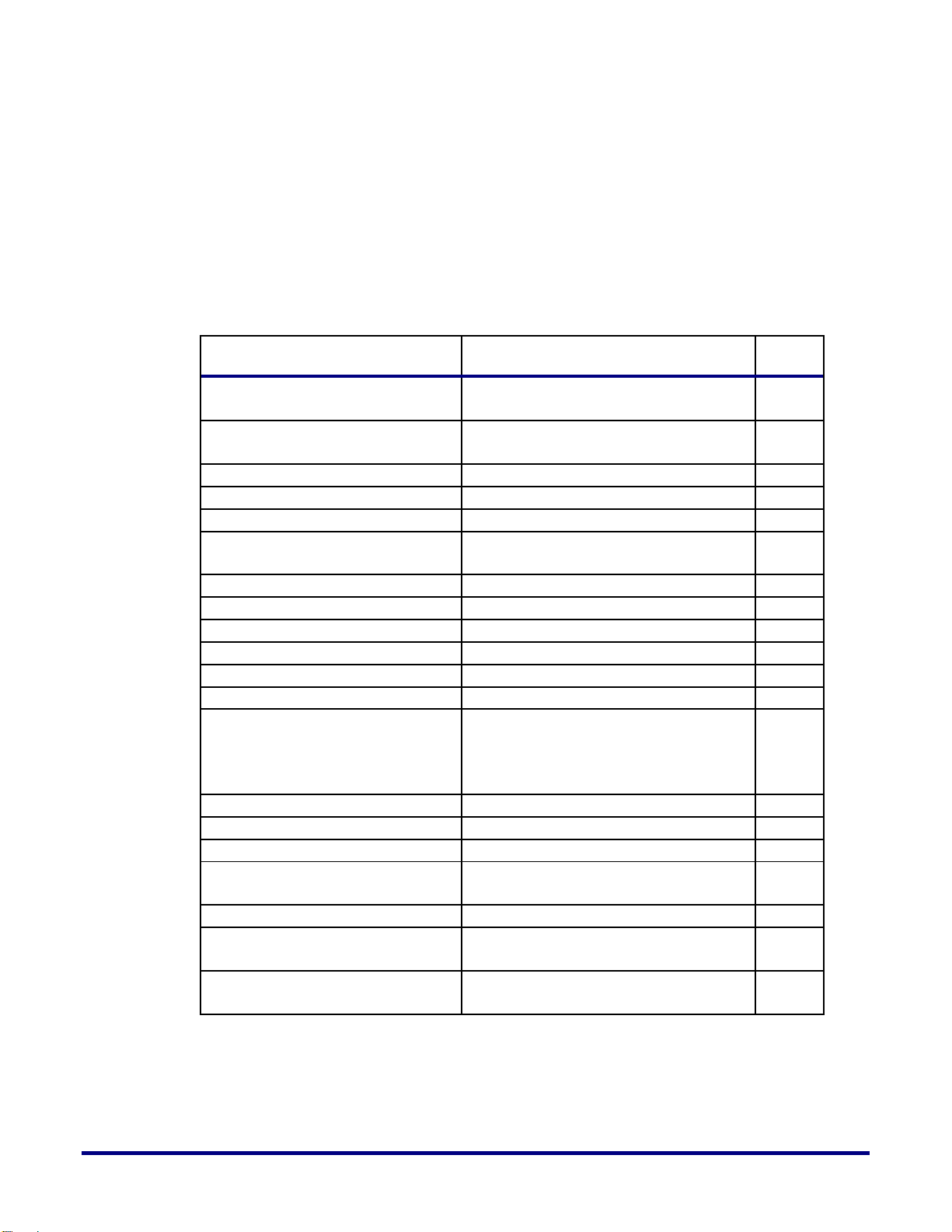
Resource
Number of resources
Clock input pins
24 single ended (12 differential)
Global core clocks
48
Direct core clocks
32
Clocks per IP column in fabric
16
Boundary clocks
16
Global boundary clock hierarchy levels
4
Local boundary clock hierarchy levels
2
Clock generators (CGs)
4 (1 per device corner)
Phase Locked Loops (PLLs)
16 (4 in each CG)
Clock and Reset Networks Overview
Speedster22iHD FPGAs have two hierarchical clock networks: a core clock network and a
boundary clock network.
The core clock network is the hierarchical network that feeds resources in the FPGA fabric.
There are two types of core clock networks: a global and a direct. Both of them have common
input sources: Clock input pins and PLL outputs which make up the Clock Generator (CG)
and recovered SerDes input clocks. These input sources get channeled in from both the north
and south sides of the device, and are then fed into the FPGA core through a central trunk.
The boundary clock network is a fully programmable clock network in the IO ring, unique to
Speedster22iHD FPGAs, that provides for significant advantages when clocking IO ring
resources at high frequencies. The boundary clock network is comprised of a low skew global
boundary clock network and a lower jitter local boundary clock network. The inputs to the
boundary clock network are CGs.
Reset signals generated internally or coming from GPIOs are funneled through the Reset
Input Blocks in the device corners into the FPGA core and the IO ring. The IO ring contains a
dedicated reset network but for distribution to core logic, the clock network resources
described above are used.
Clock Resource Counts
The following table lists the clock resources available on Speedster22iHD FPGAs.
Table 1: Clock Resource Counts on Speedster22iHD FPGAs
4 UG027, May 21, 2014
Page 5
5
Reset Resource Counts
Resource
Number of resources
Reset input pins
32 - 40 (pkg dependent)
Reset input blocks
4
Reset signal groups in IO ring
2
Reset bus width in IO ring
16
The following table lists the reset resources available on Speedster22iHD FPGAs.
Table 2: Reset Resource Counts on Speedster22iHD FPGAs
UG027, May 21, 2014
Page 6

Clock Sources
As mentioned earlier, the clock sources are Clock Generators (CGs) and recovered SerDes
input clocks.
There are four CGs on a Speedster 22iHD FPGA, one in each corner of the device. Each CG
contains six clock I/O buffers (CBs) and four Phase Locked Loops (PLLs). The clock buffers
can be used differential I/Os or single‐ended I/Os. If these I/Os are not used as clock buffers,
they can be used as generic inputs or outputs.
The PLLs are low jitter, wide range, independent multi-phase outputs with glitch-free phase
rotators that can be used for PLL outputs of up to 2 GHz for core circuit applications. The
PLLs support both integer mode and fractional mode operation.
Each pair of SerDes lanes is provided one reference clock. Each SerDes lane has its own pair
of PLLs listed below to generate and forward clocks to the fabric:
Thus each SerDes lane provides two word-clocks (Tx and Rx) to the fabric.
a. A transmit PLL, which synthesizes the Tx clock directly from the reference clock,
and then a slower Tx word-clock for data-input from the fabric,
b. A receive PLL, which synthesizes a Rx bit-clock (and corresponding word-clock)
from the incoming data-stream.
For source synchronous transfers, there are additional clock networks known as byte-lane
clock networks that may be used especially when a small amount of logic in the fabric needs
clocking. In these cases, clocks can be routed directly into the fabric along with the data.
Reset Sources
Each corner of a Speedster22i FPGA has an individual Reset Input Block. This block receives
external reset inputs as well as inputs generated internally within the device. External reset
inputs can be driven by dedicated clock pads as well as a number of GPIOs located in the
East-North (EN), East- South (ES), West-North (WN) or West-South (WS) sides of the device.
Internal reset inputs are driven through data and clock paths in the logic fabric.
The inputs to the Reset Input Block generated either externally or internally are required to
be active‐low and glitch free. The input resets can be either asynchronous or synchronous. An
asynchronous reset is synchronized for de‐assertion to each and every clock domain where it
is utilized. A synchronous reset does not need to be synchronized to the same clock domain
but is synchronized when used in any other clock domain not synchronous with the current
clock domain.
6 UG027, May 21, 2014
Page 7

7
Core Clock Network
This chapter focuses solely on the core clock network, illustrating the global and direct core
clock network hierarchies and providing a more in-depth look at the different components
that make up these networks.
Global and Direct Core Clock Network
Global Core Clock Network
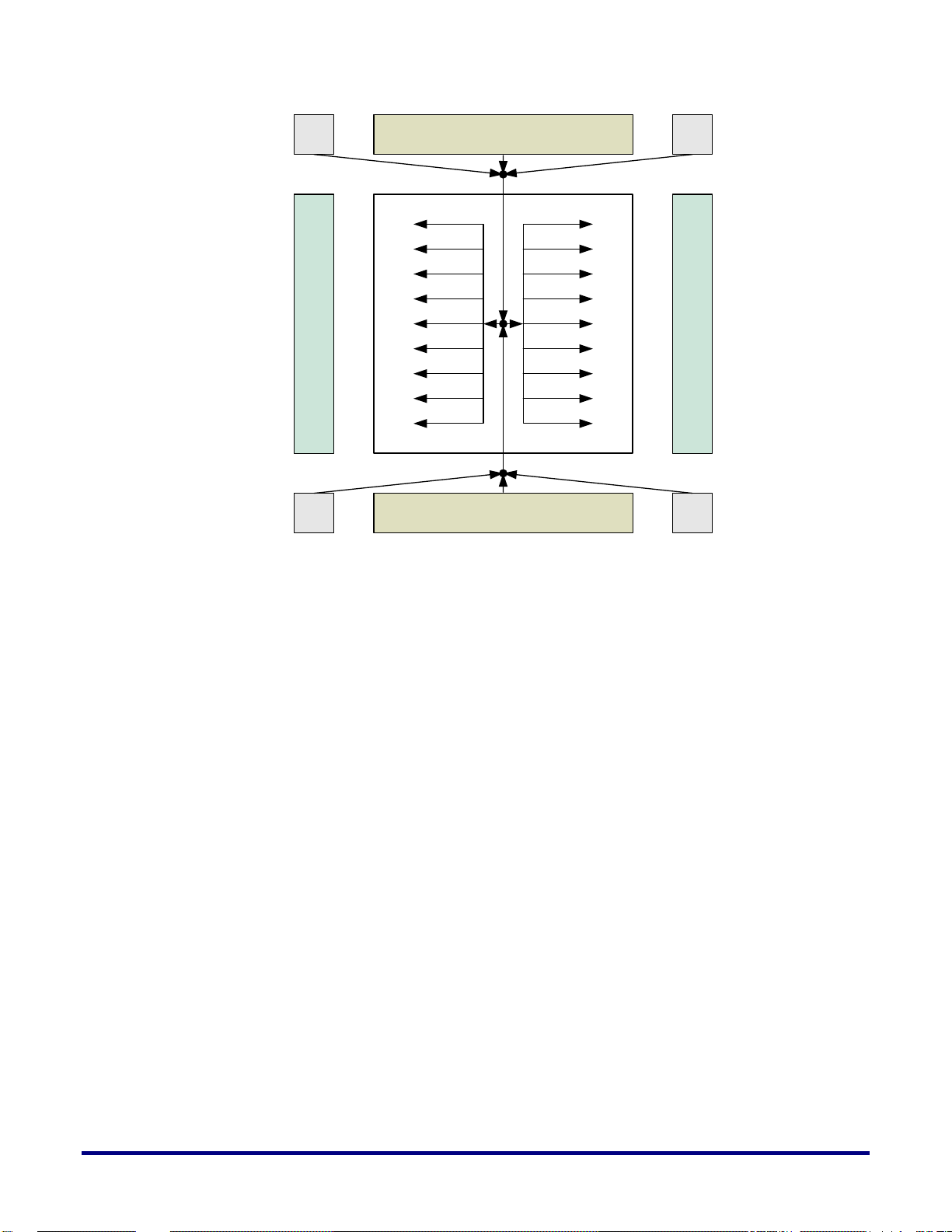
The global core clock network is a balanced and low-skew H-tree that enables clock
distribution to all parts of the Speedster 22iHD FPGA fabric. Clock signals coming in from
the top and bottom CGs and SerDes blocks are routed through a clock hub and aggregated at
the center of the device. These are then provided to all clock regions (see section on Clock
Region for details) on both the west and east sides.
As shown in Table 1, a total of 48 global clock signals are generated in the clock hub. These
are then distributed to all clock regions. Every clock region supports up to a maximum of 16
clocks, and it is able to select, amongst other sources, any of the 48 available global clocks.
Figure 1 below provides a high level illustration of the routing and connection paths for the
H-tree global core clock network.
UG027, May 21, 2014
Page 8
GPIO GPIO
SerDes
SerDes
GCG
GCG
GCG
GCG
Figure 1: Global Core Clock Network
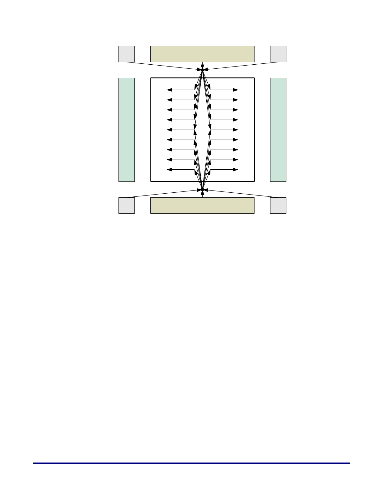
Direct Core Clock Network
The direct core clock network is a distribution system that provides for much lower clock
insertion delay, which is particularly useful for more complex designs that utilize multiple
clocks and require clocks to be internally generated and re-distributed to certain parts of the
FPGA fabric. Each branch of the direct clock network is restricted to the clock region it
reaches. Furthermore, direct clocks in each of the clock regions have different insertion
delays, which may result in significant inter-region clock skew.
The clock sources for the direct core clock network are fundamentally the same as those for
the global core clock network. The main difference between the direct and global clocks is
that direct clocks get distributed to the clock regions directly out of the top and bottom clock
muxes, without going through the clock hub (H-tree) in the center of the device.
There are a total of 32 direct clocks coming in from the top clock mux, and 32 coming in from
the bottom clock mux. A pre-designated set of 12 clocks from this group of 32 is distributed
to every clock region. Once inside the clock region, these 12 clocks are then muxed with other
incoming clocks to provide for the set of 16 that ultimately goes into the LUTs, memories and
DSPs in that clock region.
Figure 2 below illustrates the direct core clock network hierarchy.
8 UG027, May 21, 2014
Page 9
9
GPIO GPIO
SerDes
SerDes
GCG
GCG
GCG
GCG
Figure 2: Direct Core Clock Network
UG027, May 21, 2014
Page 10

Core Clock Network Components
SerDes
PLL
GCGs
PLL
PLLs
Clock
Buffers
PLL
GCGs
PLL
PLLs
Clock
Buffers
PLL
GCGs
PLL
PLLs
SerDes
Clock
Buffers
PLL
GCGs
PLL
PLLs
Clock
Buffers
I/O
Bank
Byte LanesByte Lanes
I/O
Bank
Byte LanesByte Lanes
I/O
Bank
Byte LanesByte Lanes
I/O
Bank
Byte LanesByte Lanes
Clock Region W1
Clock Region Wn
Clock Region E1
Clock Region En
Clock
Hub
Clock Mux
Top
Clock Mux
Bottom
CRMU
Wn
CRMU
E1
CRMU
En
CRMU
W1
Figure 3 provides block level highlights of the different core clock network components on
the Speedster 22iHD FPGA. These are color coded to better distinguish between them. The
sections below provide more in depth explanations of these different components.
Figure 3: Core Clock Network Components on the FPGA
Clock Generator (CG)
There are four Clock Generators (CGs) on a Speedster 22iHD FPGA, one in each corner of the
device. Each CG contains six clock I/O buffers (CBs) and four Phase Locked Loops (PLLs) and
each PLL has four output counters.
The six clock buffers can be used either as three differential I/Os or six single‐ended I/Os. If
these I/Os are not used as clock buffers, they can be used as generic inputs or outputs. These
buffers can be easily identified in the pin table or the package spreadsheet provided by ACE,
by filtering the USE column to show the clock pins. Each of these clock pins can be uniquely
identified by referencing one of the four bank locations (CB0, CB1, CB2 and CB3
corresponding to NW, SW, SE and NE respectively) as well as the pad number (0-6). The
table snapshot from the package spreadsheet below illustrates these concepts.
10 UG027, May 21, 2014
Page 11

11
Table 3: Snapshot of HD1000 52.5mm package spreadsheet to show clock buffers
Port_Name
DIFF-PAIR
USE
BANK
PURPOSE
CLK/RST USE
pad0_clk_bank_ne
P
C
CB3
USER
CLK RST
pad0_clk_bank_nw
P
C
CB0
USER
CLK RST
pad0_clk_bank_se
P
C
CB2
USER
CLK RST
pad0_clk_bank_sw
P
C
CB1
USER
CLK RST
pad1_clk_bank_ne
N
C
CB3
USER
CLK RST
pad1_clk_bank_nw
N
C
CB0
USER
CLK RST
pad1_clk_bank_se
N
C
CB2
USER
CLK RST
pad1_clk_bank_sw
N
C
CB1
USER
CLK RST
pad2_clk_bank_ne
P
C
CB3
USER
CLK RST
pad2_clk_bank_nw
P
C
CB0
USER
CLK RST
pad2_clk_bank_se
P
C
CB2
USER
CLK RST
pad2_clk_bank_sw
P
C
CB1
USER
CLK RST
pad3_clk_bank_ne
N
C
CB3
USER
CLK RST
pad3_clk_bank_nw
N
C
CB0
USER
CLK RST
pad3_clk_bank_se
N
C
CB2
USER
CLK RST
pad3_clk_bank_sw
N
C
CB1
USER
CLK RST
pad4_clk_bank_ne
P
C
CB3
USER
CLK RST
pad4_clk_bank_nw
P
C
CB0
USER
CLK RST
pad4_clk_bank_se
P
C
CB2
USER
CLK RST
pad4_clk_bank_sw
P
C
CB1
USER
CLK RST
pad5_clk_bank_ne
N
C
CB3
USER
CLK RST
pad5_clk_bank_nw
N
C
CB0
USER
CLK RST
pad5_clk_bank_se
N
C
CB2
USER
CLK RST
pad5_clk_bank_sw
N
C
CB1
USER
CLK RST
Ref Clk
Divider
PFD /
CP / LF
Sigma-
delta
Fbk Clk
Divider
Phase Rotator w/
Divider
Mux
VCO
8-phase
16 bit
4 independent
outputs
Feedback clock
from clock tree
UG027, May 21, 2014
Phase Locked Loop (PLL)
The PLLs are low jitter, wide range, independent multi-phase outputs with glitch-free phase
rotators that can be used for PLL outputs of up to 1066MHz for core circuit applications. The
block diagram below shows a high-level view of the PLL architecture.
Figure 4: PLL Architecture
Page 12

The PLL contains the following major blocks: reference clock divider, feedback divider,
sigma-delta modulator, phase rotator with divider, mux to select internal or external
feedback signal, phase-frequency detector, charge pump, loop filter and VCO.
The input reference clock can be divided by the reference clock divider. The divider ratio (M)
range is 1 to 63 with 50% duty-cycle. This PLL only supports reference clock range of 30MHz
to 400MHz (after reference clock divider frequency).
The feedback divider ratio (Q) range is 2 to 255 in integer mode with 50% duty cycle. In
fractional mode, the PLL supports 8 to 254 in the integer part. The fractional part (F)
resolution is 16-bit, which is generated by a sigma-delta modulator.
The phase rotator can shift the output clock phase by 1/8th of the internal VCO clock period
at a time. It contains a 50% duty cycle divider with ratio (N) of 1 to 63. The phases of each of
the 4 phase rotators can be independently adjusted, so can the divider ratios. All 4 phase
rotator’s phase can be re-set simultaneously.
The VCO is a 4-stage differential ring oscillator with 8-phase outputs. The VCO also has a
extra divide-by-2 option circuit for process variation backup purpose. It can be turned on in
case the process is too fast.
The PLL reference clock can come from any of the 6 IO buffers in the same CG, or from any
of the four outputs of the preceding PLL. E.g., the rclk of PLL 1 can be driven by PLL 0 (the
order is 0 -> 1 -> 2 -> 3 -> 0). The PLL reference clock is divided by the reference clock divider
(6-bit: 1 to 63) before being sent to the PFD. The VCO generates 8 equally separated phases,
one of which is sent to the feedback divider through a mux to allow the PLL running in short
loop operation without de-skew. All 8-phases are sent to 6 phase rotators which can
independently select one of the 8 phases. This then goes through an output divider (6-bit: 1 to
63) before being sent out of the PLL block. One of the 4 output clocks, after going through the
clock distribution tree, has an option to be sent to the feedback divider for de-skew
functionality.
The PLL has 3 modes of feedback clock selection:
1. Internal feedback mode: the VCO clock is divided by the feedback divider only. In this
mode, the PLL can have both integer and fractional divider ratios. But the PLL does not
provide deskew capability. The VCO frequency is related to the reference clock frequency
through: Fvco=(Q/M)*Fref in integer mode, and Fvco=(Q.F/M)*Fref in fractional mode.
2. External feedback mode: the VCO clock is divided by the output divider inside the phase
rotator. Only the integer divider ratio is supported. The output clock from one of the phase
rotators is sent to downstream logic. After being consumed by the downstream logic, the
clock is fed back to PLL for deskew. Please note in this mode, it is recommend to not rotate
the phase rotator in the feedback path, if the lock signal is required to be high during the
operation because the phase rotator action introduces phase errors to the PLL, and could lead
to the PLL losing lock. The other 5 phase rotators can be used for rotating the phase. The
VCO frequency is related to the reference clock frequency through: Fvco=(N/M)*Fref.
3. Mixed feedback mode: This mode should only be used when the output divider range is
not enough. The VCO is divided by the output divider inside one of the phase rotators. The
output clock from the phase rotator goes to the downstream logic. The consumed clock is
sent back to the PLL for deskew. The feedback clock is sent to the feedback divider before it is
sent to PFD. Only the integer mode of the feedback divider ratio should be used in this mode.
The VCO frequency is related to the reference clock frequency through: Fvco=(Q*N/M)*Fref.
12 UG027, May 21, 2014
Page 13
13
The PLL IP comes with a built-in LDO and a Band Gap reference circuit. The LDO takes
Performance Features
Units
Bandwidth
Tracking between 1/10th and 1/8th of
reference clk freq
Feedback Divider
8 (2 to 255); in fractional mode, only
support 8 to 254
Bits
Post Divider
6
Bits
Reference Clock Divider
6
Bits
Number of Post Dividers
4
Fractional Synthesizer Support
PLL includes a 16-bit accurate fractional
synthesizer.
Spread Spectrum
No support
Feedback signal delay(max)
Half of divided reference clock period
ns
Operation Mode
Normal, Bypass, Pwrdn, Reset
Internal phase separation
12.5% output cycle
Internal phase accuracy
+/-3.5% output cycle at 2GHz
Output phase accuracy
+/-5% output cycle at 2GHz
Number of selectable Phases
8
Each PLL output clock can select and
change to one of the 8 phases
dynamically in a glitch-free manner.
Maximum Duty cycle variation
50% +/- 2%
Static Phase Error
+/- 80
ps
Jitter – Period
+/- 4% p2p of output clock period
%
Jitter – Cycle to Cycle
5ps (integer divider mode, typical); 8ps
(fractional divider mode, typical)
ps
Jitter – Long Term
Worst case 100ps/sigma
ps
Lock Time
500 ref clk periods (integer mode);
1000 ref clk periods (fractional mode)
Reset divide-by-1 output
frequency range
30MHz – 50 MHz
external analog voltage (PA_VDD, 1.5V to 1.8V) and generates internal analog voltage to
provide cleaner supply voltage to PLL. The Band Gap reference circuit provides the reference
voltage for the LDO. In order to calibrate the Band Gap reference and the LDO, without
requiring an analog pin, a built-in ADC reference is included in the PLL block as well.
The PLL can be controlled in two ways: one way is to use the direct control through the
interface pins; the other is to use AHB CSR interface. More extensive descriptions of these
controls can be found in UG021 - Speedster22i Macro Cell Library. The PLL performance
specifications are listed in Table 4 below.
Table 4: PLL Performance Specifications
In ACE, users are provided with the option to configure PLLs using the “Basic PLL” IP
generator or the “Advanced PLL” IP generator. The “Basic PLL” generator helps the users in
setting up and configuring the PLL parameters and modes of operation based on the users
desired behavior.
UG027, May 21, 2014
Page 14

On the other hand, the “Advanced PLL” gives users much more flexibility in setting up the
PLL0 PLL1 PLL2 PLL3
4 4 4
PLL reference clock
PLL reference clock PLL reference clock
PLL reference clock
PLL counter outputs PLL counter outputs PLL counter outputs PLL counter outputs
4
From clock
bank
From clock
bank
From clock
bank
From clock
bank
To clock network To clock network To clock network To clock network
individual PLL parameters, settings, counter values etc. and gives the user full control over
exactly how the PLL is tuned. Obviously, in the case of the “Advanced PLL”, it is the user’s
responsibility to ensure that the settings provided match the intended behavior.
PLL Cascading: An important feature with the PLLs in every corner of the device is the
ability to cascade them by feeding the output clock of one to the reference clock input of the
subsequent one. Each PLL can be cascaded with its neighbor only, in a circular fashion: PLL0
can generate the refclk for PLL1; PLL1 can generate the refclk for PLL2; PLL2 for PLL3; and
PLL3 for PLL0. Any of the four counter outputs can be used as a reference clock for the
neighboring PLL. However, in the rare cases where that is insufficient, a PLL output can also
be configured as bypass, so that the output follows refclk. So if PLL0 must provide the refclk
for both PLL1 and PLL2, you could use one output of PLL1 as bypass (leaving 3 outputs for
regular use), and drive PLL2 with that bypassed clock.
Refer to Figure 5 below for a graphical representation of this feature.
Figure 5: PLL Reference Clock Cascading
The reference clock cascading mechanism is useful for a number of different reasons. Two of
the main ones are as follows:
It allows for a wider range of output phases/frequencies to be generated without
needing to use the fractional mode feature in PLLs.
It enables a larger set of clock outputs to be generated based off of the same reference
clock, without requiring changes at the board-level.
Clock Mux
There are two clock muxes in the FPGA, one at the top center of the device and one at the
14 UG027, May 21, 2014
bottom center. Each one of these is used to aggregate 128 clock signals coming in from all of
the clock sources described earlier (also shown below) and output a 32-bit bus that can be fed
Page 15

15
into the clock hub. Figure 6 below provides a detailed view of the internals of the clock mux
Clock Mux
Top
6
16
16
6
16
16
52
128 to 32 Fully
General Crossbar
From Top SerDes Lanes
32
From NW Clock Generator through
Global Boundary Clock
From NW Clock Generator through
Local Boundary Clock
To Clock Hub
No Connect No Connect
From NE Clock Generator through
Global Boundary Clock
From NE Clock Generator through
Local Boundary Clock
located at the top center of the device.
Clock Hub
The clock hub in the center of the device collects the two 32-bit buses coming in from the top
and bottom clock muxes, as well as a 16-bit bus from the data interconnect to generate the 48bit global clock bus.
The 48-bit global clock bus (shown in green) travels back up and down the length of the clock
hub to feed each of the clock regions.
The 32-bit buses coming in from the top and bottom (shown in red) are actually also the
direct core clocks which are tapped off at each of the clock regions. A 12-bit subset of this 32bit bus is selected as shown in Figure 7 below.
The 16-bit bus coming in from the data interconnect (shown in blue), is one of the ways of
getting a signal from data generated in the FPGA fabric into a clock network, and this path is
the only way of generating a global core clock signal from the interconnect data.
Figure 7 below provides a detailed view of the clock hub.
Figure 6: Detailed View of the Top Clock Mux
UG027, May 21, 2014
Page 16

Clock
Hub
32
From Clock Mux Top
32
From Clock Mux Bottom
16
From data
interconnect
in fabric
80 to 48
Crossbar
48
48
48
48
48
48
48
48
48
12
12
12
12
To Clock
Region W1
To Clock
Region W2
12
12
12
12
To Clock
Region Wn-1
To Clock
Region Wn
To Clock
Region E1
To Clock
Region E2
To Clock
Region En-1
To Clock
Region En
Global Core Clk
Direct Core Clk
H-Tree
Clock Region
Figure 7: Detailed View of the Clock Hub
Clock regions in Speedster 22iHD FPGAs have fixed heights, such that a DDR controller on
the left and right sides of the IO ring can feed 3 clock regions each. The width, and
consequently, number of IP columns is variable. This means that both the size and number of
clock regions will vary from one member of the Speedster 22iHD FPGA family to the other.
The total clock region count in any device is 3 x the total number of DDR controllers on the
die. There are an equal number of clock regions on the left and right halves of the device.
Each clock region is fed 48 global and 12 direct clock inputs from the clock hub. The clock
selection for these is detailed in Figure 7 above. In addition a 16-bit bus from the data
interconnect can also be fed here to drive only the clocks in a specific region.
All of these inputs are fed into a Clock Region Management Unit (CRMU) which performs an
appropriate clock selection and outputs a 16-bit bus which is then fanned out to all of the
columns of RLBs, MULTs, LRAMs and BRAMs in that clock region. An illustration of a clock
region is shown in Figure 8 below.
16 UG027, May 21, 2014
Page 17

17
12
RLBs
RLBs
RLBs
CRMU
RLBs
RLBs
RLBs
BRAMs
BRAMs
BRAMs
BRAMs
BRAMs
BRAMs
RLBs
RLBs
RLBs
RLBs
RLBs
RLBs
MULTs
MULTs
MULTs
MULTs
MULTs
MULTs
RLBs
RLBs
RLBs
RLBs
RLBs
RLBs
BRAMs
BRAMs
BRAMs
BRAMs
BRAMs
BRAMs
LRAMs
LRAMs
LRAMs
LRAMs
LRAMs
LRAMs
MULTs
MULTs
MULTs
MULTs
MULTs
MULTs
48
Global Clocks
from Clock Hub
Direct Clocks
from Clock Mux
Clock
Region
16
From data
interconnect in fabric
16
Figure 8: Detailed View a Clock Region
Clock Region Management Unit (CRMU)
Every clock region contains a Clock Region Management Unit (CRMU), which does a variety
of functions, including clock muxing and clock division.
The CRMU has two clock muxing blocks, each taking in half of the incoming global clocks
and direct clocks as well as a quarter of the signals coming in through the 16-bit data
interconnect bus. These signals go through a 32-8 mux and are then optionally divided down.
These 8-bit buses are then aggregated to form the 16-bit clock output bus which is provided
to all of the columns in the clock region fabric. The clock division and gating logic is
controlled by signals coming in from the data interconnect bus.
A summary of the features available in the CRMU are as follows:
a. Divider, with 5 (static) divide-by settings: 1, 2, 4, 6, 8,
b. Dynamic Clock gate, allowing real-time clock gating (for power management),
c. Glitchless mux, allowing dynamic muxing between different clock sources for that
particular clock region.
Figure 9 below illustrates the internals of the CRMU.
UG027, May 21, 2014
Page 18

CRMU
32 to 8
Crossbar
Additional
Control
Logic
32 to 8
Crossbar
Additional
Control
Logic
Clk Div &
Gating
Clk Div &
Gating
6
24
2
6
24
Global Core Clocks
from Clock Hub
Direct Core Clocks
from Clock Mux
2
From data
interconnect in fabric
16
From data
interconnect in fabric
16
8
8
8
8
16
To Fabric
Columns
Global Core Clocks
from Clock Hub
Direct Core Clocks
from Clock Mux
Clk Div &
Gating
Clock Divider
(1, 2, 4, 6 or 8)
Clock Gate Clock Switch
Enable
Select /
Deselect
Clk_Out
Clk_In Clk_In2
Figure 9: Detailed View of a Clock Region Management Unit (CRMU)
Figure 10 below provides a more in-depth look at the 3 features available in the CRMU.
Clock division logic is controlled by static configuration memory bits. The clock gate relies on
an “Enable” input to the logic, while the glitchless clock switch module uses select/deselect
logic to select between 2 different clock inputs. The divider and gating or switching logic can
also be cascaded as shown. Note that Figure 10 is a conceptual view of the circuitry for one
instance only and these functions exist for all of the clock inputs.
Figure 10: Internals of the Clock Division, Gating and Switching Circuitry
18 UG027, May 21, 2014
Page 19

19
Junctions
Data-to-Clock Junctions
There are multiple junction-points in the fabric where a data-interconnect signal can drive a
clock network signal:
a. Clock Hub (16 data inputs; already discussed above),
b. CRMU (4 data inputs per region; already discussed above),
c. RLB input (any Logic Cluster clock can be driven by a selected data signal),
d. Selected BRAM, LRAM, or Multiplier input.
Based on the fanout and other requirements of the clock signal that is generated in the data
interconnect portion of the programmable logic fabric, an appropriate junction point would
be selected by ACE.
Clock-to-Data Junctions
Switching elements can allow some LUT inputs, BRAM inputs, LRAM inputs, and BMAC
inputs to be driven by a signal outputted by the CRMU. In particular, this would allow
certain functions that may have high fanout like register resets and clock enables to be driven
by signals from the CRMU.
UG027, May 21, 2014
Page 20

Byte-Lane Clocks
Byte-Lanes 0-3Byte Lanes 4-7Byte Lanes 8-12
Core Fabric
West-North (WN) IO Cluster
Clock Region West 1
Clock Region West 2
Clock Region West 3
RLBs
RLBs
MULTs
MULTs
16
16
RLBs
RLBs
MULTs
MULTs
16
16
RLBs
RLBs
MULTs
MULTs
16
16
Clk
div4
Clk
div2
IO Ring
For source synchronous transfers, where data and clock are both sent from the IO ring to the
core, using one of the clock networks as described above would result in a large skew
between the data and the clock.
For this reason, there is a dedicated entry point from the byte lanes into the clock inputs of
the clock regions, via the data interconnect route in the fabric into the CRMU. These are
known as byte-lane clocks and are predominantly used to forward data strobe (dqs) clock
signals from the PHY into the FPGA fabric. A byte lane in a Speedster22i FPGA consists of 12
I/O buffers. For every set of 13 byte-lanes making up an IO cluster, (which corresponds to the
IOs used in the hard DDR3 controllers), there is a clock signal that is used for sampling the
data at the IO PHY. This clock signal can go through 2 clock dividers, a divide-by-2 clock
module and a divide-by-4 clock module. The outputs of these modules, which correspond to
the half-rate or quarter-rate clocks in a memory interface application can be forwarded to the
3 clock regions corresponding to that IO site. Note that for memory interface applications,
usage of mesochronous synchronizers in the Rx datapath will allow for clock domain
crossing between the dqs clock domain and a core clock network, eliminating the need for
clock forwarding into the fabric. For more details, please refer to the Memory PHY User
Guide.
Figure 11 below illustrates the the entry point of these byte-lane clocks into a clock region in
the WN site of the device. These clocks are muxed with the clocks coming from the CRMU
and are then fed to all of the blocks in the fabric IP column.
Figure 11: Byte-Lane Clocks in a Clock Region
20 UG027, May 21, 2014
Page 21

21
Boundary Clock Network
Core Fabric
GCG GCG
GCG GCG
GCM
QCM
RCM
BCM
Core Fabric
GCG GCG
GCG GCG
GCM
BCM
Example Global Boundary Clock Network Example Local Boundary Clock Network
The boundary clock network is an architectural feature available in Speedster22iHD FPGAs
to help improve IO ring performance in high speed applications. There are two variants of
the boundary clock network: The first is a global boundary clock network, which ensures that
clocks coming in from all 4 sides of the device traverse a muxing network that provides for
low skew between them. The second is a local boundary clock network, which is a shortened
and more direct low jitter path from the CGs to the IO ring resources that need to be clocked.
The main advantages provided by the boundary clock network are as follows:
1. Resources clocked in the IO ring have much higher noise immunity to noise from the
fabric. The IO ring and boundary clock network are on a separate supply from the
rest of the core fabric, so even with very high core resource usage and toggle, power
supply noise is essentially eliminated.
2. Usage of the local boundary clock network provides for a much cleaner, lower jitter,
lower insertion delay path from the CGs to the IO ring resources.
3. Availability of additional clocking resources in the boundary frees up the core clock
network resources to be used for clocking in the fabric.
The main drawbacks of the local boundary clock network are that (a) usage of the different
local boundary clock networks requires more clocks coming into the different CG corners,
and (b) it provides for clocks that can have significant skew between them. Figure 12 below
shows a high-level illustration of the distinction between global and local boundary clock
networks.
Figure 12: Distinction Between Global and Local Boundary Clock Networks
UG027, May 21, 2014
There are four levels of hierarchy and muxing in the boundary clock network. These are, in
hierarchical order:
Page 22

Global Clock Mux (GCM)
GCMSW
Fabric Core
GCMNW
GCMNE
16 clock networks
RCMWS
RCMWN
BCMWS BCMWN
16 clock networks
GCMSE
QCMWS
QCMSW
ZGMSW_IQ_CLK[15:0]
ZGMSW_IQ_CLK[15:0]
ZGMSE_IQ_CLK[15:0]
ZGMNW_IQ_CLK[15:0]
ZGMSE_IQ_CLK[15:0]
ZGMNE_IQ_CLK[15:0]
ZQMWS_IR_CLK[15:0]
ZQMSW_IR_CLK[15:0]
QCMWN
QCMNW
ZQMWN_IR_CLK[15:0]
ZQMNW_IR_CLK[15:0]
ZGMSW_IB_CLK[15:0]
ZGMNW_IB_CLK[15:0]
ZRMWN_IB_CLK[15:0]ZRMWS_IB_CLK[15:0]
ZGMNW_IQ_CLK[15:0]
ZGMNE_IQ_CLK[15:0]
QCMES
QCMSE
ZQMES_IR_CLK[15:0]
ZQMSE_IR_CLK[15:0]
QCMEN
QCMNE
ZQMNE_IR_CLK[15:0]
RCMES
RCMEN
ZQMEN_IR_CLK[15:0]
BCMEN
ZGMNE_IB_CLK[15:0]
ZRMEN_IB_CLK[15:0]
BCMES
ZRMES_IB_CLK[15:0]
ZGMSE_IB_CLK[15:0]
RCMNW
BCMNW
ZRMNW_IB_CLK[15:0]
RCMSW
BCMSW
ZRMSW_IB_CLK[15:0]
16 clock networks16 clock networks
BCMSE
RCMSE
ZRMSE_IB_CLK[15:0]
RCMNE
BCMNE
ZRMNE_IB_CLK[15:0]
RCMWC
16 clock networks
ZRMWC_IB_CLK[15:0]
16 clock networks
RCMEC
BCMEC
ZRMEC_IB_CLK[15:0]
BCMWC
Clock Mux
Clock Mux
Quadrant Clock Mux (QCM)
Region Clock Mux (RCM)
Byte-Lane Clock Mux (BCM)
The global boundary clock network traverses through each of these mux stages, whereas the
local boundary clock uses a shortened path that ties the output of the GCM directly into the
BCM. The full boundary clock network architecture is shown in detail in Figure 13 below,
with red paths highlighting the GCM to QCM connectivity, the blue paths highlighting the
QCM to RCM connectivity and the dark yellow paths highlighting the RCM to BCM paths.
The local boundary clock network is shown in green.
Figure 13: Full Boundary Clock Network Architecture
Note that usage of the local boundary clock is more restrictive in that the South BCMs can
only be fed by the South GCMs/CGs. The North and Center BCMs can only be fed by the
North GCMs/CGs. The output of the BCMs can additionally be used to enter the core clock
22 UG027, May 21, 2014
network, though this is generally not recommended.
Page 23

23
Clock Setting and Reporting
Much of the decision making and optimization for clock selection is automatically done by
the ACE tool to prevent no-routes. However, ACE does provide users with some options to
specify the type of clock networks they wish to use for particular implementations.
The clock type can be specified for a particular CG output in the sdc file as shown below. The
three options available are: {trunk, direct_trunk, boundary}.
Set_clock_type –direct_trunk {‘Hierarchical name of CG output’}
Trunk and direct_trunk correspond to the global and direct core clock networks, respectively.
For the boundary clock network, ACE will automatically decide whether to use the global or
local boundary clock network depending on placement and the application.
Once the clock constraints are specified in the design and the design goes through a full ACE
compilation flow, the routing step outputs text and html files called
“{design_name}_clocks_routed” describing the clock relationships, clock constraints and
clock regions in the design. The clock regions section provides detailed information on how
each of the clocks in the design were routed and how they are distributed in the used FPGA
clock regions, including the boundary. A legend is also provided in the file to help decipher
the routing details.
UG027, May 21, 2014
Page 24

Reset Network
Reset
Input
Block
PLL
GCGs
PLL
PLLs
Clock
Buffers
I/O
Bank
Byte LanesByte Lanes
FPGA Core
This chapter examines the reset network in a little more detail and provides information on
the different networks, reset sources as well as associated circuitry in Speedster22i FPGAs.
Reset Sources and the Reset Input Block
Each corner of a Speedster22i FPGA has an individual Reset Input Block. This block receives
external reset inputs as well as inputs generated internally within the device. External reset
inputs can be driven by dedicated clock pads as well as a number of GPIOs located in the
East-North (EN), East- South (ES), West-North (WN) or West-South (WS) sides of the device.
Internal reset inputs are driven through data and clock paths in the logic fabric. Figure 14
below illustrates a Reset Input Block in the bottom-left corner of the device and the
appropriate signals coming in to the block.
The inputs to the Reset Input Block generated either externally or internally are required to
be active‐low and glitch free. The input resets can be either asynchronous or synchronous.
For resets to IO ring resources, there is automatic reset synchronization (using boundary
clocks) and pipelining to ensure that while reset assertion is asynchronous, the deassertion is
synchronous. The purpose of the reset pipeline insertion is to ensure that reset deassertion in
the I/O ring meets setup and hold time requirements, and occurs at the same clock tick for all
targets. This is done because (a) the STA does not verify timing requirements in the I/O ring,
24 UG027, May 21, 2014
Figure 14: Reset Input Block
Page 25

25
and (b) even if it did the user wouldn’t be able to do anything to fix timing problems in the
D Q D Q
nclrnclr
To nclr ports of logic
receiving reset
Nrst
Clk
Port_Name
DIFF-PAIR
USE
BANK
PURPOSE
CLK/RST USE
pad_en_byteio0_dq0
P
G
B50
USER
RST
pad_en_byteio0_dq1
N
G
B50
USER
RST
pad_en_byteio0_dq2
P
G
B50
USER
RST
pad_en_byteio0_dq3
N
G
B50
USER
RST
pad_es_byteio12_dq6
P
G
B32
USER
RST
pad_es_byteio12_dq7
N
G
B32
USER
RST
pad_es_byteio12_dq8
P
G
B32
USER
RST
pad_es_byteio12_dq9
N
G
B32
USER
RST
pad_wn_byteio0_dq0
P
G
B00
USER
RST
pad_wn_byteio0_dq1
N
G
B00
USER
RST
pad_wn_byteio0_dq2
P
G
B00
USER
RST
pad_wn_byteio0_dq3
N
G
B00
USER
RST
pad_ws_byteio12_dq6
P
G
B22
USER
RST
pad_ws_byteio12_dq7
N
G
B22
USER
RST
pad_ws_byteio12_dq8
P
G
B22
USER
RST
pad_ws_byteio12_dq9
N
G
B22
USER
RST
pad0_clk_bank_ne
P
C
CB3
USER
CLK RST
pad0_clk_bank_nw
P
C
CB0
USER
CLK RST
I/O ring.
For resets going into the FPGA fabric, the guideline is to use logic in the fabric to ensure that
the resets can be synchronized to the particular clock domains. One way of doing this is
shown in Figure 15 below, whereby the logic enables going into reset asynchronously, but
coming out of it asynchronously.
Figure 15: Reset Synchronization Logic
As far as the external reset sources arc concerned, all dedicated clock buffers can be used as
inputs to the Reset Input Block. Also, for IO banks bonded out on the East-North (EN), EastSouth (ES), West-North (WN) or West-South (WS) sides of the device, a total of four IO pads
can be used as inputs to the Reset Input Block. The table below from the HD1000 52.5mm
package spreadsheet dumped out by ACE highlights all the RST pins that can be used. The 8
shown in the red rectangle are only available on the 52.5mm package and not on the 45mm
package since the IO banks on the East-South (ES) and West-North (WN) sides of the device
are not bonded out on the 45mm package.
Table 5: Snapshot of HD1000 52.5mm package spreadsheet to show resets
UG027, May 21, 2014
Page 26

Port_Name
DIFF-PAIR
USE
BANK
PURPOSE
CLK/RST USE
pad0_clk_bank_se
P
C
CB2
USER
CLK RST
pad0_clk_bank_sw
P
C
CB1
USER
CLK RST
pad1_clk_bank_ne
N
C
CB3
USER
CLK RST
pad1_clk_bank_nw
N
C
CB0
USER
CLK RST
pad1_clk_bank_se
N
C
CB2
USER
CLK RST
pad1_clk_bank_sw
N
C
CB1
USER
CLK RST
pad2_clk_bank_ne
P
C
CB3
USER
CLK RST
pad2_clk_bank_nw
P
C
CB0
USER
CLK RST
pad2_clk_bank_se
P
C
CB2
USER
CLK RST
pad2_clk_bank_sw
P
C
CB1
USER
CLK RST
pad3_clk_bank_ne
N
C
CB3
USER
CLK RST
pad3_clk_bank_nw
N
C
CB0
USER
CLK RST
pad3_clk_bank_se
N
C
CB2
USER
CLK RST
pad3_clk_bank_sw
N
C
CB1
USER
CLK RST
pad4_clk_bank_ne
P
C
CB3
USER
CLK RST
pad4_clk_bank_nw
P
C
CB0
USER
CLK RST
pad4_clk_bank_se
P
C
CB2
USER
CLK RST
pad4_clk_bank_sw
P
C
CB1
USER
CLK RST
pad5_clk_bank_ne
N
C
CB3
USER
CLK RST
pad5_clk_bank_nw
N
C
CB0
USER
CLK RST
pad5_clk_bank_se
N
C
CB2
USER
CLK RST
pad5_clk_bank_sw
N
C
CB1
USER
CLK RST
Reset Distribution
Reset signals need to be distributed to both the FPGA core fabric as well as the IO ring, which
includes the GPIOs, SerDes and hard IP. There is no dedicated reset network in the FPGA
programmable fabric, so distribution to the core is generally recommended to be done using
the global and direct clock network resources described above, to take advantage of timing
and load balancing.
For the IO ring, there is a dedicated 16-bit reset bus that ensures a balanced reset assertion
and de-assertion latency across the entire device. This is made possible by pipelining the
reset distribution using the clock to which the reset is synchronized.
Each side of the device has two groups of reset signals running in opposite directions. Each
group consists of eight reset signals each, spanning the entire edge of the device in a
pipelined manner. The two groups of reset signals are tapped at each I/O bank or logic block
(eg. DDR controller, SERDES), using a configurable pipeline multiplexer with configurable
pipelined latency. The configuration is automatically set for each individual multiplexer to
balance the latency for the reset signals across the entire device. The outputs of the pipeline
multiplexer are subsequently distributed to the reset network inside the IO banks and logic
blocks. This is shown in Figure 16 below.
26 UG027, May 21, 2014
Page 27

27
FPGA Core
Reset
source
Reset
source
Reset
source
Reset
source
8 bit
8 bit
8 bit
8 bit
8 bit
8 bit
8 bit
8 bit
P
Logic Block
P P P
P P
P
P P P
P P
P
P
P
P
P
P
P
P
P
P
P
P
Logic Block
Logic Block Logic Block
Logic Block Logic Block
Logic Block Logic Block
P
P
P
P
P
P
P
P
PP
PP
PP
PP
Programmable
Pipeline
Figure 16: IO Ring Reset Network
UG027, May 21, 2014
Page 28

Revision History
Date
Version
Revisions
04/05/2013
1.0
Initial Achronix release.
05/22/2013
1.1
Incorporated additional inputs from engineering.
06/07/2013
1.2
Updated PLL description and diagrams.
04/24/2014
1.3
Updated byte-lane clocks. Added in boundary clock network
and settings sections. Corrected clock sources.
05/01/2014
1.4
Updated PLL specs.
05/21/2014
1.5
Added information about PLL cascading.
The following table shows the revision history for this document.
28 UG027, May 21, 2014
 Loading...