

Acesonic AM-888 User Manual
AM-888 500-Watt Dual 32 Bit DSP Karaoke Mixing Amplifier
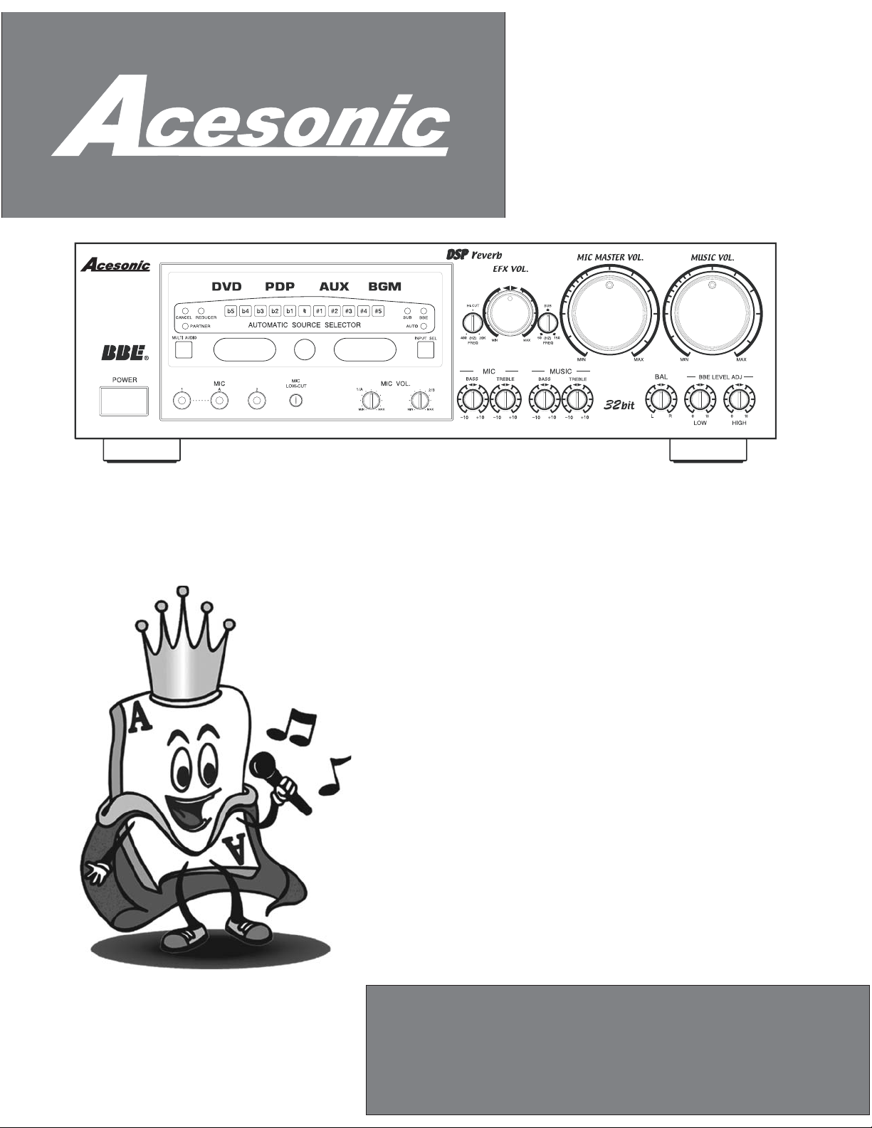
Acesonic AM-888
500 Watt Karaoke Mixing Amplifier-
With DSP Interface
USER’S MANUAL
NOTE:
To ensure this component will work safely and to
its fullest potential, please read this user’s manual
carefully before operation and keep for future
reference.
www.acesonic.com

Warnings, Cautions and OthersWarnings, Cautions and Others
Mises en garde, precautions et indications diversesMises en garde, precautions et indications diverses
CAUTION
RISK OF ELECTRIC SHOCK
RISK OF ELECTRIC SHOCK
DO NOT OPEN
DO
NOT OPEN
CAUTION: TO REDUCE THE RISK OF ELECTRIC SHOCK.
CAUTION: TO REDUCE THE RISK OF ELECTRIC SHOCK.
DO NOTREMOVE COVER (OR BACK).
NOT REMOVE COVER (OR BACK).
DO
NO USERSERVICEABLE PARTS INSIDE.
USER SERVICEABLE PART S INSIDE.
NO
REFER SERVICING TO QUALIFIED SERVICE PERSONNEL.
SERVICING TO QUALIFIED SERVICE PERSONNEL.
REFER
The lightning flash with arrowhead symbol, within an
The lightning flash with arrowhead symbol, within an
equilateral
equilateral triangle is intended to alert the user to the
presence
presence of uninsulated within the
product's
product's enclosure that may be of sufficient magnitude
to
constitute a risk of electric shock to persons.
to constitute a risk of electric shock to persons.
The exclamation point within an equilateral triangle is
The exclamation point within an equilateral triangle is
intended to alert the user to the presence of important
intended
operating and maintenance (servicing) instructions in
operating
the literature accompanying the appliance.
the
CAUTION
CAUTION
To reduce the risk of electrical shocks, fire, etc:
To reduce the risk of electrical shocks, fire, etc:
not remove screws, screws, covers or cabinet.
1.Do not remove screws, screws, covers or cabinet.
1.Do
not expose this appliance to rain or moisture.
2.Do
2.Do not expose this appliance to rain or moisture.
FCC INFORMATION (U.S.A.)FCC INFORMATION (U.S.A.)
1.This equipment has been tested and found to
1.This equipment has been tested and found to
comply with the limits for a Class B digital device,
comply
pursuant
pursuant to part 15 of the FCC Rules. These limits
are
are designed to provide reasonable protection
against
against harmful interference in a residential
installation.
installation.
This
This equipment generates, uses and can radiate
radio
radio frequency energy and, if not installed and
used
used in accordance with the instructions, may
cause
cause harmful interference to radio
communications.
communications. However, there is no guarantee
that
that interference will not occur in a particular
installation.
installation. If this equipment does cause harmful
interference
interference to radio or television reception, which
can
can be determined by turning the equipment off and
on,
on, the user is encouraged to try to correct the
interference
interference by one or more of the following
measures:
measures:
Reorient
Reorient or relocate the receiving antenna.
Increase
Increase the separation between the equipment
and
and receiver.
Connect
Connect the equipment into an outlet on a circuit
different
different from that to which the receiver is
connected.
connected. Consult the dealer or an experienced
radio/TV
radio/TV technician for help.
2. When connecting this product to
2. When connecting this product to
IMPORTANT:
IMPORTANT:
accessories and/or another product use only high
accessories
quality
quality shielded cables. Cable(s) supplied with this
product
product MUST be used. Follow all installation
instructions.
instructions. Failure to follow instructions could
void
void your FCC authorization to use product in the
U.
U. S. A.
with the limits for a Class B digital device,
to part 15 of the FCC Rules. These limits
designed to provide reasonable protection
harmful interference in a residential
equipment generates, uses and can radiate
frequency energy and, if not installed and
in accordance with the instructions, may
harmful interference to radio
interference will not occur in a particular
be determined by turning the equipment off and
the user is encouraged to try to correct the
or relocate the receiving antenna.
the separation between the equipment
receiver.
the equipment into an outlet on a circuit
from that to which the receiver is
technician for help.
shielded cables. Cable(s) supplied with this
MUST be used. Follow all installation
your FCC authorization to use product in the
S. A.
triangle is intended to alert the user to the
of uninsulated within the
enclosure that may be of sufficient magnitude
to alert the user to the presence of important
and maintenance (servicing) instructions in
literature accompanying the appliance.
dangerous
dangerous voltage
voltage
However, there is no guarantee
If this equipment does cause harmful
to radio or television reception, which
by one or more of the following
Consult the dealer or an experienced
and/or another product use only high
Failure to follow instructions could
For Canada/Pour le Canada
For Canada/Pour le Canada
CAUTION: TO PREVENT ELECTRIC SHOCK,
CAUTION: TO PREVENT ELECTRIC SHOCK,
MATCH WIDE BLADE OF PLUG TO WIDE SLOT,AND
MATCH
FULLY INSERT.
FULLY INSERT.
ATTENTION:
ATTENTION:
ELECTRIQUES,
ELECTRIQUES, INTRODUIRE LA LAME LA PLUS
LARGE
LARGE DE LA FICHE DANS LA BORNE
CORRESPONDANTE
CORRESPONDANTE DE LA PRISE ET POUSSER
JUSQUAU
JUSQUAU FOND.
For Canada/Pour le Canada
For Canada/Pour le Canada
THIS DIGITALAPPARATUS DOES NOT EXCEED
THIS DIGITALAPPARATUS DOES NOT EXCEED
THE CLASS B LIMITS FOR RADIO NOISE
THE
EMISSIONS
EMISSIONS FORM DIGITALAPPARATUSAS SET
OUT IN THE
OUT IN THE INTERFERENCE-CAUSING
EQUIPMENT STANDARD
EQUIPMENT STANDARD ENTITLED DIGITAL
APPARATUS,
APPARATUS, ICES-003 OF THE DEPARTMENT OF
COMMUNICATIONS.
COMMUNICATIONS. CET APPAREIL NUMERIQUE
RESPECTE
RESPECTE LES LIMITES DE BRUITS RADIO
ELECTRIQUES APPLICABLES AUX APPAREILS
ELECTRIQUES APPLICABLES AUX APPAREILS
NUMERIQUES
NUMERIQUES DE CLASSE B PRESCRITES DANS
LA NORMESUR
LA NORMESUR LE MATERIEL BROUILLEUR:
APPAREILS
APPAREILS NUMERIQUES , NMB-003 EDICTEE
PAR
PAR LE MINISTRE DES COMMUNICATIONS.
Caution
Caution
Disconnect the electrical plug to shut off power
Disconnect the electrical plug to shut off power
completely. The POWER on the unit is not off from the
completely. The
electrical
electrical plug when the POWER button on the front
panel
panel is not pressed in.
WIDE BLADE OF PLUG TO WIDE SLOT,AND
POUR
POUR EVITER LES CHOCS
EVITER LES CHOCS
INTRODUIRE LA LAME LA PLUS
DE LA FICHE DANS LA BORNE
DE LA PRISE ET POUSSER
FOND.
CLASS B LIMITS FOR RADIO NOISE
FORM DIGITALAPPARATUS AS SET
""
INTERFERENCE-CAUSING
"
ENTITLED DIGITAL
"
ICES-003 OF THE DEPARTMENT OF
CET APPAREIL NUMERIQUE
LES LIMITES DE BRUITS RADIO
DE CLASSE B PRESCRITES DANS
LE MATERIEL BROUILLEUR:
NUMERIQUES , NMB-003 EDICTEE
LE MINISTRE DES COMMUNICATIONS.
POWER on the unit is not off from the
plug when the POWER button on the front
is not pressed in.
IMPORTANT FOR LASER PODUCTSIMPORTANT FOR LASER PODUCTS
1.
1.
CLASS1
CLASS1 LASER PRODUCT
2. Visible laser radiation when open and
2. Visible
DANGER:
DANGER:
interlock
interlock failed or defeated.Avoid direct exposure to
beam.
beam.
CATION:
3. Do
3. Do not open the top cover. There are no
CATION:
user
user service able parts inside the unit. Leave all
servicing
servicing to qualified service personnel.
4. CAUTION
REPRODUCTION
4. CAUTION LABEL,
REPRODUCTION OF LABEL:
PLACED
PLACED INSIDE THE UNIT.
LASER PRODUCT
laser radiation when open and
failed or defeated. Avoid direct exposure to
not open the top cover. There are no
service able parts inside the unit. Leave all
to qualified service personnel.
OF LABEL:
LABEL,
INSIDE THE UNIT.
2
Important Safety instructionsImportant Safety instructions
1. These Instructions.Read1. These Instructions.Read
2. These Instructions.Keep2. These Instructions.Keep
3. All Warnings.Heed3. All Warnings.Heed
4. All Instructions.Follow4. All Instructions.Follow
5. not use this product near water.Do5. not use this product near water.Do
6. only with dry cloth.Clean6. only with dry cloth.Clean
7. not block any ventilation openings.Do7. not block any ventilation openings.Do
8. not install near any heat sources such as radiators, heat
8. not install near any heat sources such as radiators, heat
Do
Do
register, stoves, or other apparatus (including amplifiers)
register,
that
that produce heat.
Do
9. not defeat the safety purpose of the polarized or
9. not defeat the safety purpose of the polarized or
Do
grounding-type plug. A polarized plug has two blades with
grounding-type
one
one wider than the other.A grounding type plug has two
blades
blades and third grounding prong. The wide blade or the
third
third prong are provided for your safety. If the provided plug
does
does not fit into your outlet, consult an electrician for
replacement
replacement of the obsolete outlet.
10. the power cord from being walked on or pinched
10. the power cord from being walked on or pinched
Protect
Protect
particularly at plugs, convenience receptacles, and the
particularly
point
point where they exit from the apparatus.
11. use attachments and accessories specified by the
Only11. us e attachments and accessories specified by the
Only
manufacturer.
manufacturer.
Use
12. only with the cart, stand, tripod,
12. only with the cart, stand, tripod,
Use
bracket, or table specified by the
bracket,
manufacturer,
manufacturer, or sold with the apparatus.
When
When a cart is used, use caution when
moving
moving the cart.
13. this apparatus during lightning storms or unused
13. this apparatus during lightning storms or unused
Unplug
Unplug
for long period of time. Apparatus combination to avoid
for
injury
injury from tip-cover.
Refer
14. all servicing to qualified service personnel.
14. all servicing to qualified service personnel.
Refer
Servicing is required when the apparatus has been
Servicing
damaged
damaged in any way, such as power-supply cord or plug is
damaged,
damaged, liquid has been spilled or objects have fallen into
the
the apparatus, the apparatus has been exposed to rain or
moisture,
moisture, does not operate normally, or has been dropped.
stoves, or other apparatus (including amplifiers)
produce heat.
plug. A polarized plug has two blades with
wider than the other.A grounding type plug has two
and third grounding prong. The wide blade or the
prong are provided for your safety. If the provided plug
not fit into your outlet, consult an electrician for
of the obsolete outlet.
at plugs, convenience receptacles, and the
where they exit from the apparatus.
or table specified by the
or sold with the apparatus.
a cart is used, use caution when
the cart.
long period of time. Apparatus combination to avoid
from tip-cover.
is required when the apparatus has been
in any way, such as power-supply cord or plug is
liquid has been spilled or objects have fallen into
apparatus, the apparatus has been exposed to rain or
does not operate normally, or has been dropped.
Overloading
18.
18.
Overloading
not overload wall outlets, extension cords, or integral
Do not overload wall outlets, extension cords, or integral
Do
convenience
convenience receptacles as this can result in a risk of fire
electric shock.
or
or electric shock.
Object
19.
19.
Object and Liquid Entry
Never push objects of any kind into this product through
Never
openings
openings as they may touch dangerous voltage points or
short-out
short-out parts that could result in a fire or electric shock.
Never
Never spill liquid of any kind on the product.
Replacement
20.
20.
Replacement Parts
replacement parts are required, be sure the service
When replacement parts are required, be sure the service
When
technician
technician has used replacement parts specified by the
manufacturer
manufacturer or have the same characteristics as the
original
original part. Unauthorized substitutions may result in fire,
electric
electric shock, or other hazards.
Safety
21.
21.
Safety Check
completion of any service or repairs to this product,
Upon completion of any service or repairs to this product,
Upon
the service technician to perform safety checks to
ask
ask the service technician to perform safety checks to
determine
determine that the product is in proper operating
condition.
condition.
22.
22.
23.
23.
24.
24.
or Ceiling Mounting
Wall
Wall or Ceiling Mounting
product should be mounted to a wall or ceiling only as
The product should be mounted to a wall or ceiling only as
The
recommended
recommended by the manufacturer.Any mounting of the
product
product should follow the manufacturer instructions, and
should
should use a mounting accessory recommended by the
manufacturer.
manufacturer.
Wet
location marking
Wet location marking
Apparatus shall not be exposed to dripping or splashing
Apparatus
no objects filled with liquids, such as vases, shall be
and
and no objects filled with liquids, such as vases, shall be
placed
placed on the apparatus.
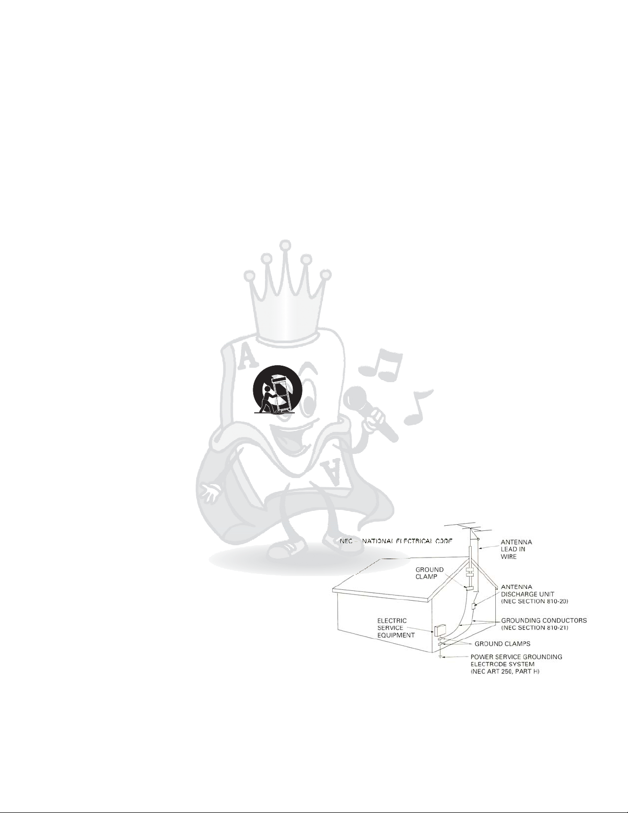
Outdoor Antenna
Outdoor Antenna Grounding
an outside antenna or cable system is connected to the
If an outside antenna or cable system is connected to the
If
product,
product, be sure the antenna or cable system is grounded
as to provide some protection against voltage surges
so
so as to provide some protection against voltage surges
built-up static charges. Article 810 of the National
and
and built-up static charges. Article 810 of the National
Electrical
Electrical Code, ANSI/NFPA 70, provides information with
regard
regard to proper grounding of the mast and supporting
structure,
structure, grounding of the lead-in wire to an antenna
discharge
discharge unit, size of grounding conductors, location of
antenna
antenna discharge unit, connection to grounding
electrodes,
electrodes, and requirements for the grounding electrode.
figure below.
See
See figure below.
receptacles as this can result in a risk of fire
and Liquid Entry
push objects of any kind into this product through
as they may touch dangerous voltage points or
parts that could result in a fire or electric shock.
spill liquid of any kind on the product.
Parts
has used replacement parts specified by the
or have the same characteristics as the
part. Unauthorized substitutions may result in fire,
shock, or other hazards.
Check
that the product is in proper operating
by the manufacturer.Any mounting of the
should follow the manufacturer instructions, and
use a mounting accessory recommended by the
shall not be exposed to dripping or splashing
on the apparatus.
Grounding
be sure the antenna or cable system is grounded
Code, ANSI/NFPA 70, provides information with
to proper grounding of the mast and supporting
grounding of the lead-in wire to an antenna
unit, size of grounding conductors, location of
discharge unit, connection to grounding
and requirements for the grounding electrode.
This
15. product should be operated only from the type of
15. product should be operated only from the type of
This
source indicated on the marking label. If you are not
power source indicated on the marking label. If you are not
power
of the type of power supply to your home, consult your
sure
sure of the type of power supply to your home, consult your
product
product dealer or local power company. For products
intended
intended to operate from battery power, or other sources,
refer
refer to the operating instructions.
Protective Attachment
16.
16.
Protective Attachment Plug
The product is equipped with an attachment plug having
The
overload
overload protection. This is a safety feature. See
Instruction
Instruction Manual for replacement or resetting of
protective
protective device. If replacement of the plug is required, be
sure
sure the service technician has used a replacement plug
specified
specified by the manufacturer that has the same overload
protection
protection as the original plug.
Power
17.
17.
Power Lines
An outside antenna system should not be located in the
An
vicinity
vicinity of overhead power lines or other electric light or
power
power circuits, or where it can fall into such power lines or
circuits.
circuits. When installing an outside antenna system,
extreme
extreme care should be taken to keep from touching such
power
power lines or circuits as contact with them might be fatal.
dealer or local power company. For products
to operate from battery power, or other sources,
to the operating instructions.
Plug
product is equipped with an attachment plug having
protection. This is a safety feature. See
Manual for replacement or resetting of
device. If replacement of the plug is required, be
the service technician has used a replacement plug
by the manufacturer that has the same overload
as the original plug.
Lines
outside antenna system should not be located in the
of overhead power lines or other electric light or
circuits, or where it can fall into such power lines or
When installing an outside antenna system,
care should be taken to keep from touching such
lines or circuits as contact with them might be fatal.
Servicing
25.
25.
Servicing
your product is not operating correctly or exhibits a
If your product is not operating correctly or exhibits a
If
marked
marked change in performance and you are unable to
restore
restore normal operation by following the detailed
procedure
procedure in its operating instructions, do not attempt to
service
service it yourself as operating instructions, do not attempt
to
to service it yourself as opening or removing covers may
expose
expose you to dangerous voltage or other hazards. Refer
all
all servicing to qualified service personal.
3
change in performance and you are unable to
normal operation by following the detailed
in its operating instructions, do not attempt to
it yourself as operating instructions, do not attempt
service it yourself as opening or removing covers may
you to dangerous voltage or other hazards. Refer
servicing to qualified service personal.
Acesonic AM-888
Thank you for purchasing Acesonic s AM 888 Acesonic takes pride in
providing our costmers with only the most advanced and highest quality
karaoke products on the market. Please read trough this USER’S MANUAL
before operation to ensure proper usage, and keep for future refence. Enjoy!
'-.
Table of Contents
Warnings and Caution 2
Safety Instructions 3
Table of Contents 4
Included Accessories 4
Front Panel Functions and Operation 5,6
Rear Panel Functions and Operation 7,8,9
Remote Control Functions 10
DSP Sound-Effect Setting 11
Default Volume Setting 12
Player Connection 13,14
Troubleshooting 15
Specifications 16
Supplmental User’s Guide A,B,C,D
Warranty Information 17 18
,
Included Accessories
Please check to make sure all accessories are included. If anything
is missing, please contact your dealer immediately.
- 1 Remote Control
- 2 AAA Batteries
- 1 RCA Audio/Video Cable (yellow/red/white)
- 1 AC Power Adapter Cord
- Rack-Mount Kit
- User's Manual
About this Manual
For easy reference, names of all functions and/or
components on the hardware and accessories are denoted
by upper-case letters.
4
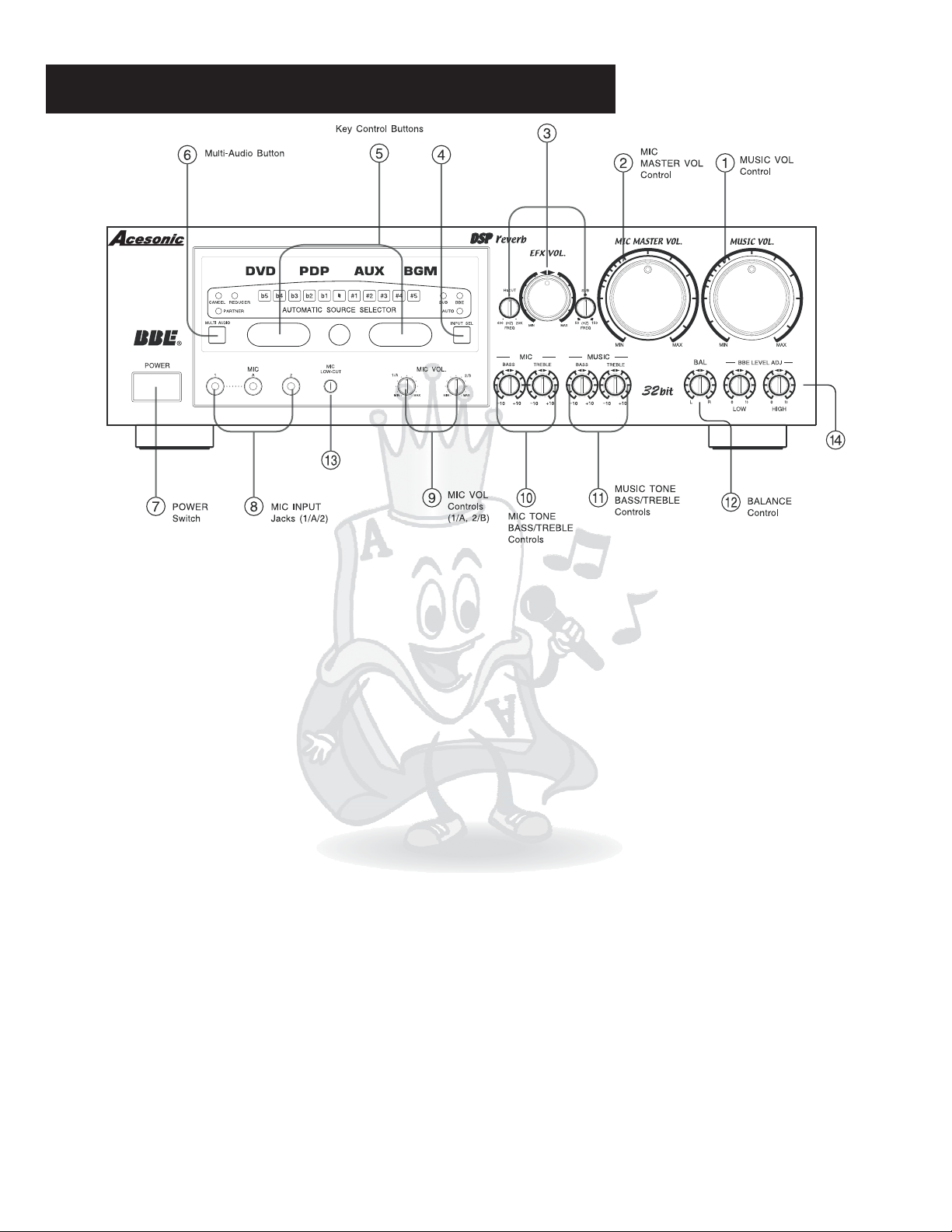
Front Panel Function and Operation
EFFECT(ECHO/REVERB) Control
INPUT SELECT
AM-888 500-Watt Dual 32 Bit DSP Karaoke Mixing Amplifier
MIC Low-Cut Control
BBE LEVEL
Low/High Adjustment
1.MUSIC VOL control -
Adjusts the volume output for the selected music channels. Turn
counter-clockwise to decrease volume and clock-wise to increase volume.
2.MIC MASTER VOL control -
Adjusts the overall volume output for all three microphone
channels, collectively. Turn counter-clockwise to decrease volume and clock-wise to
increase volume.
3.EFFECT VOLUME VOL-
Center big knob is used for adjusting the sound effects, echo and
reverberation effects. The two small knobs are used for adjusting high and low frequency
cutting range.
4.INPUT SELECT-
Selects the external source connected to DVD INPUT,PDP INPUT,AUX
INPUT or BGM INPUT. Corresponding indicator light will illuminate when selected.
5.KEY CONTROL-
These buttons are used for adjusting the music scale. Each step is for1/4
tone adjustment, and the middle button is for the original/standard key. After a song finishes,
or the music has been terminated for more than 4 seconds, the system will automatically
return to the original key.
6.MULTI. AUDIO(Sound selector)
*CANCEL:
-
The original vocal(usually on the right channel) of the multiplex audio song can be
removed,and only the music(usually on the left channel) would be played.
*PARTNER
microphone) the original vocal(right channel) of the multiplex audio song will e automatically
:If there is no signal detected from Micrphone input(you don’t sing with a
,
played.Once a signal is detected from Microphone input( you start singing with a
microphone), the original vocal(right channel) will be removed automatically.
*REDUCER:
For stero music, only when both left and right channel have vocal, the original
vocal would be removed. This feature might not work very well if the left and right channel
have different voice sound.
*When no indicator light is on, it is the common vocal accompaniment. Nothing changes from
the original audio signal.
7.POWER ON/OFF button -
8.MIC INPUT jacks (1, A, 2) -
Turns the AM-888 on or off.
1/4 inch inputs for microphones.
5

Front Panel Function and Operation
EFFECT(ECHO/REVERB) Control
INPUT SELECT
AM-888 500-Watt Dual 32 Bit DSP Karaoke Mixing Amplifier
MIC Low-Cut Control
BBE LEVEL
Low/High Adjustment
9. MIC VOL control (1/A,2/B)-
Independently adjusts the signal volume of each
corresponding MICROPHONE INPUT. Turn counter-clockwise to decrease volume and
clockwise to increase volume.
1/A:
Adjusts the input level of MIC 1 and MIC A.
2/B:
Adjusts microphone
microphone
the input level of MIC 2 and MIC B*. *MIC B is at the rear of the
machine.
10.MICROPHONE BASS control/MIC TREBLE control-
Adjusts the low/high audio
frequency setting from microphone inputs. Turn counter-clockwise to decrease and
clockwise to increase.
11.MUSIC BASS control/MIC TREBLE control-
Adjusts the low/high audio frequency
setting from DVD/PDP/AUX/BGM inputs. Turn counter-clockwise to decrease and clockwise
to increase.
12.BALANCE knob-
Pans the music output to the stereo left and right channels. Turn
counter-clockwise to gradually pan to the stereo left channel. Turn clockwise to gradually pan
to the stereo right channel. Center the knob for equal output from both stereo left and right
channels. (Please note: the microphone inputs will NOT be affected)
13.MICROPHONE low-cut control-
14.BBE level adjustment knobs-
Adjust the low frequency level of microphone input.
Adjusts the low/high audio frequency of BBE sound effect.
Turn clockwise to increase and counter-clockwise to decrease.
6
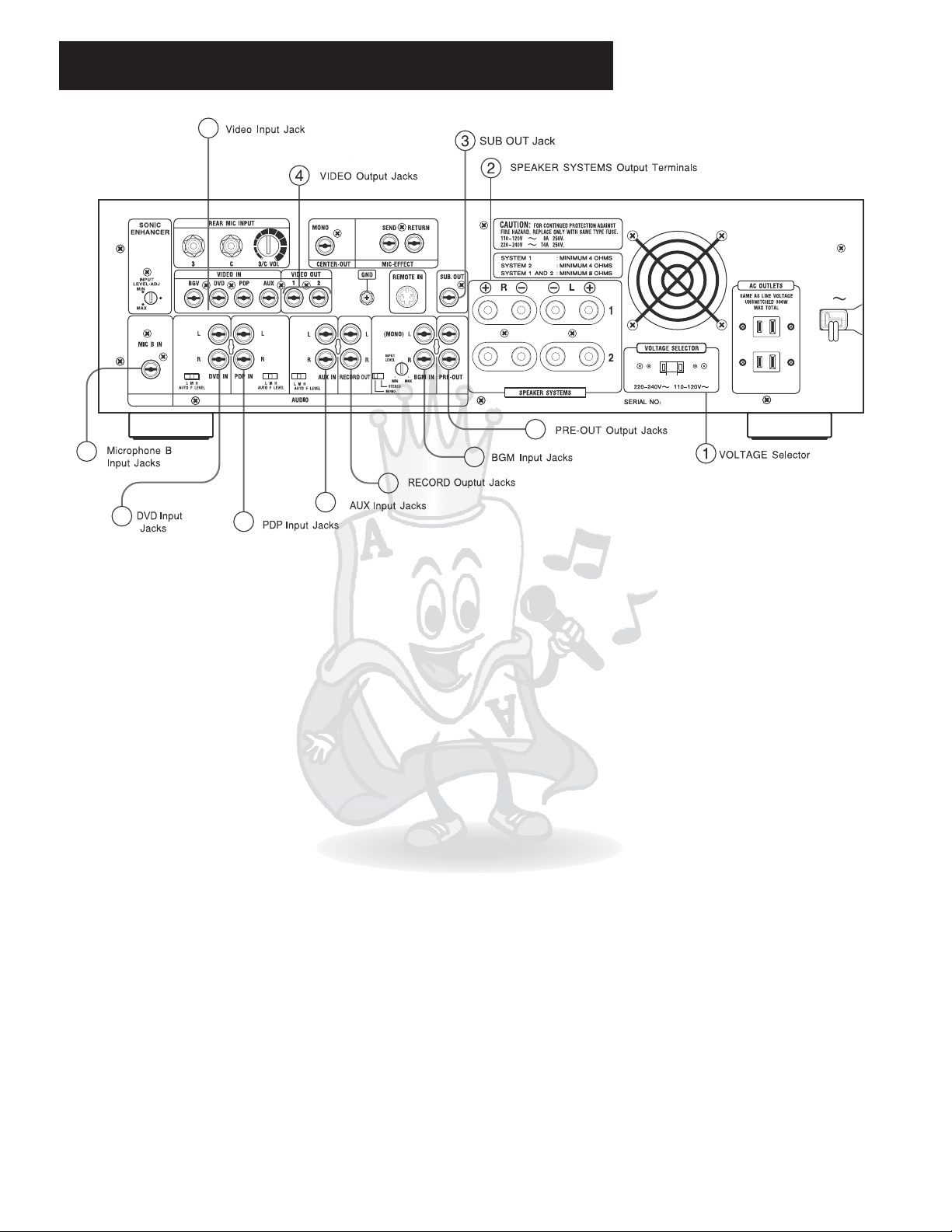
Rear Panel Function and Operation
5
12
6
10
7
8
9
11
1. VOLTAGE SELECTOR-
Voltage selection switch. Push the switch right for 115V, and left
for 230V. (Note: Different regions of the world use different voltage strength. Please check to
make sure the correct voltage is selected for your area.). Before switching, please
disconnect the power plug.
2.SPEAKER SYSTEM
- Provides audio output to stereo external speakers. Designed to be
used with bare speaker wire as well as banana connectors. The LEFT and RIGHT outputs
each consist of a positive (+, red) and negative (-, black) signal that correspond with the
inputs on each speaker. (Please see connection diagram on page 11 for proper configuration)
*SYSTEM 1: The impedance of speakers should not be lower than 4 .
*SYSTEM 2: The impedance of speakers should not lower than 4 .
18
*SYSTEM 2: The impedance of speakers should not lower than .
3.SUB OUT jack-
+beΩ
This is used for connecting a powered subwoofer, or driving passive
be Ω
Ω
subwoofer via Amplifier.
4.VIDEO OUTPUT 1 &2 jacks -
These two VIDEO RCA outputs are used for outputting OSD
video signal and also the video signal which is from DVD/PDP/AUX/BGV. These two VIDEO
output jacks can be use at the same time.
5.VIDEO INPUT jacks (DVD/PDP/AUX/BGV) -
VIDEO RCA inputs to receive video signal
from DVD/PDP/AUX/BGV.
6.Microphone B input-
Additional microphone input. User can use 2/B MIC VOL control knob
on the front panel to adjust volume.
7.DVD IN AUDIO input-
Connect to RCA Audio output jacks of an external component like
DVD(VCD) players.
8.PDP IN AUDIO input-
Connect to RCA Audio output jacks of an external component like
Plasma Display Panels.
.8.AUX IN AUDIO input-
STB AUDIO ouput jacks of CABLE TV
9.RECORD OUT-
Connect to RCAAudio input jacks of an external recording component like
Connect to RCA Audio output jacks of an external component like
.
TAPE deck. This Audio output signal is always on even when the external recording
component is not recording.
7
 Loading...