

Acesonic AM-170 User Manual
®
AM-170
250-Watt Professional Mixing Amplier
User Manual
NOTE: To ensure this system works safely and to its fullest potential, please read the User Manual before
use, and keep it handy for future reference. See important safety information on Pages 7-8.
ank you for purchasing Acesonic’s AM-170 250Watt (@ 4 Ohms) Professional Mixing Amplier.
Acesonic takes pride in providing its customers with
only the most advanced and highest quality products
on the market. With proper care and use you will
get many years of satisfying use from your Acesonic
product.
Be sure to keep original packaging in case re-shipping
is required for returns or repairs.
First Things First
Before using your AM-170, take a few simple steps:
• Check to see that your local power outlets supply
the correct voltage for the AC input.
Table of Contents
First ings First .................................................1
System Components ............................................2
Product Features ..................................................2
• Do not open the device as there are no userserviceable parts inside. For repairs, contact the
local distributor, an authorized service center or
Acesonic’s U.S. headquarters.
• Care and cleaning directions are included in this
User Manual, but preventive measures are good
common sense. Do not use the device in areas that
are wet or prone to dampness. Always allow sucient room around the device to provide sucient
air ow for cooling.
• When the device will not be used for a long period
of time, disconnect the power plug from the wall,
as well as the back of the unit, and remove all connecting cables for proper storage.
Remote Control Operations ................................4
Care & Maintenance ...........................................4
Troubleshooting ..................................................5
Initial Setup Considerations ................................2
Front Panel Operations .......................................2
Back Panel Operations ........................................3
Connecting the AM-170 .....................................6
FCC Advisory, Safety Warnings & Safe Use .......7
Company Contact Information ...........................8
1

System Components
Front Panel Operations
Your Acesonic AM-170 unit is designed for years of
enjoyment. Please take a moment to review the following instructions for its proper use and care.
Included Accessories
Your AM-170 includes the following items:
• 1 AM-170 Mixing Amplier
• 1 Remote control
• 1 AC power adapter cord
• User’s Manual, Warranty Card
If you are is missing any of these items, contact your
Acesonic dealer at once.
Product Features
e AM-170 allows you to connect mixer, player or
other audio devices directly to its stereo RCA audio
inputs for instant sound. You also have great exibility
in output choices.
• 80+80W @ 8 Ohms maximum output
• 125+125W @ 4 Ohms equivalent output
• Four A/V inputs selector
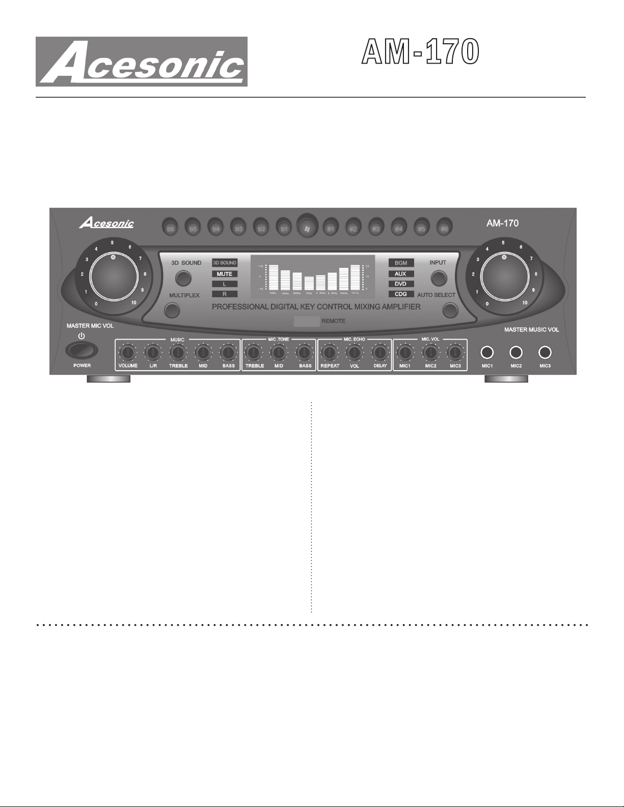
Refer to the Figure A at the top of page 3 (right).
1. KEY CONTROL - e line of buttons allows you
to raise or lower the key by six (6) semi-tones. e
center button is the original (natural) key, and at is
to the left while sharp is to the right.
2. MASTER MICROPHONE VOLUME – is
dial controls the master volume for all three microphone inputs. Turning clockwise raises the volume.
3. POWER ON/OFF button - Turns the AM-170
on or o.
4. MUSIC CONTROLS - ese control the volume,
balance and tone (Treble, Mid and Bass) of the music
output from all input sources.
5. MICROPHONE TONE - ese controls adjust
the Treble, Mid and Bass tone for all microphones
that are in use.
6. MICROPHONE ECHO – ese controls adjust
the Repeat, Volume and Delay settings for Echo.
7. INDIVIDUAL MICROPHONE VOLUME –
ese controls adjust the Volume independently for
Mic 1, Mic 2 and Mic 3.
• Microphone volume control
• Microphone bass, middle and treble control
• Microphone echo repeat and delay control
• Music bass, middle and music treble control
• Music balance control
• Five 1/4" microphone inputs: 3 front, 2 rear
• Music eect bypass switch
• Dynamic sound enhancer - Enhance a full range
of frequencies for both music and vocals
• Fully digital, color LCD display
• Record line output and subwoofer output
• One pair banana speaker outputs
Initial Setup Considerations
is basic setup guide provides simple, step-by-step
instructions for setting up your AM-170 system,
along with a complete diagram of the back panel connections and switches. Audio systems vary, so you may
need additional and/or longer cables, adaptors, etc.,
to connect your system in the way(s) you want. For
any questions, please contact your dealer or Acesonic
technical support.
8. MICROPHONE INPUTS – ree 1/4" input
jacks for microphones.
9. MASTER MUSIC VOLUME – is control adjusts the Master Volume for music coming from any
of the sources.
10. AUTO SELECT – is button enables the unit
to scan and detect the signal automatically (BGM,
AUX, DVD and CDG). When the signal is detected
and identied, the scanning will stop and you will see
the input source indicator light conrming the selection (see Item #11, below).
11. INPUT SELECTION – is button selects the
input source in manual mode. You can switch input
among BGM, AUX, DVD and CDG. e selection
will be reected by the appropriate signal indicator.
12. 3D SOUND AND MUTE – is button selects
3D Sound, for enhanced music and vocal audio, as
well as Mute. e button will toggle from o to these
two functions, then back to o on a third press.
13. MPX – is button will select among Stereo (no
light) and Left/Right, which will be indicated by the
appropriate indicator light (L or R) as shown on the
panel above and to the right of the button.
14. IR REMOTE RECEIVER – e IR Receiver
2

Figure A
1
2
12
13 10
3
4 5 6 7 8
that takes commands from the Remote Control is
located here. Do not obstruct line of sight access to
this portion of the display during use.
Figure B
1
11
15
14
15. INFORMATION DISPLAY WINDOW – is
color display shows a range of information, as well as
the frequency levels of the program material.
9
10 11
12
9
2
5
3
6
4
7 8
Back Panel Operations
Refer to the Figure B directly above.
1. MICROPHONE INPUTS – ese two 1/4" jacks
are alternate, back-panel inputs for Mic 1 and Mic 2.
Use front panel knobs to control volume and tone.
2. VIDEO INPUTS – is line of Video inputs that
take RCA connectors from the various source inputs.
Each Video input is associated with the Left and
13
Right Audio inputs directly below (see Item #3, below).
3. AUDIO – ese Audio inputs, Left and Right, accept source inputs (BGM, AUX, DVD and CDG).
4. PRE – ese RCA jacks allow you to send the signal to an external signal processor via the Ouput jacks,
and receive the processed signal back via Inputs.
5. VIDEO OUT – is RCA output jack works with
the Audio outs below it (see Item #6, below) to supply
a composite signal to an external device.
3
 Loading...