

Page 1
ACE RC
TG-6000
HEADING LOCK GYRO
INSTRUCTION MANUAL
Product no. #8072
INTRODUCTION
TG-6000 is designed for mini electric R/C helicopters.
Small-sized and light-weighted make it ideal and convenient
for installation on your mini electric R/C helicopter. Both
heading lock mode and normal mode are adopted. Also you
can use a digital servo for more precise tail control.
FEATURES
.
Heading lock mode and normal mode
.
Remote-controlled gain
.
Analog/digital servo compatible
.
Delay function
.
Simple wire connection for easy installation
.
Small and light weight
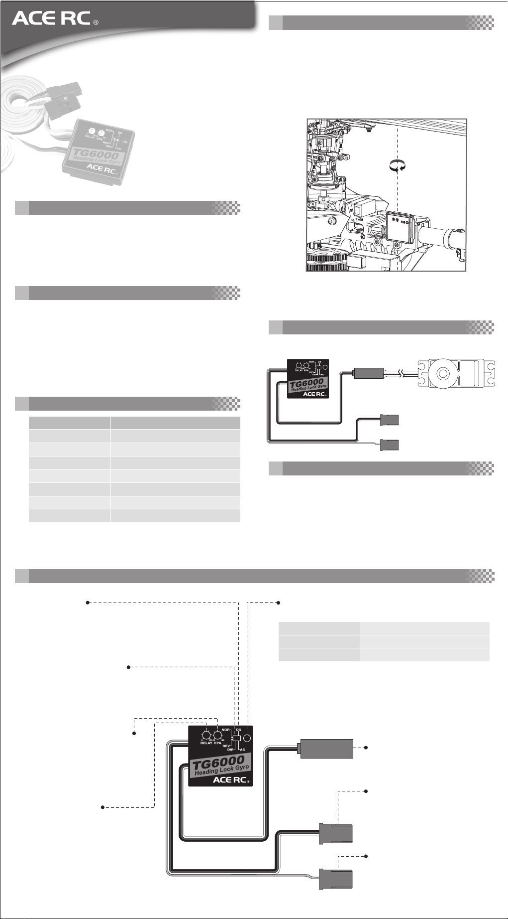
INSTALLATION
.
Before using the double-sided foam, be sure to clean the
bottom of the gyro and the fuselage where the gyro will
be attached.
.
Install the gyro as shown. Please note that the gyro must
be erected as the sensing direction is different from
others.
CONNECTION
SPECIFICATIONS
Item No.
Product Name
Control
Sensor
Voltage
Operation Temperature
Dimension(mm)
Weight(g)
8072
TG-6000
Digital Proportional Integration Control
Piezoelectric Vibrating Gyroscope
DC 4.8~6.0V
-5 ~ 50˚C
25.9 × 24.9 × 7
13.5
FUNCTION
AS/DS switch
TG-6000 is compatible with analog servo as well as
digital servo. The AS means Analog Servo while the
DS means Digital Servo. Be sure to set the switch at
AS position when using an analog servo, or the servo
will be easily destroyed.
Gyro operating direction
Switch the gyro operating direction. This setting
depends mostly on the helicopter, servo, and the
installation position of the gyro itself. Wrong
setting will result in a dangerous situation.
Connect to rudder servo
Connect to receiver
rudder channel
Connect to receiver
sensitivity switching channel
SERVO SELECTION
TG-6000 is suitable for analog and digital rudder servo.
For analog servo, set the right switch to the AS position that
means Analog Servo. For digital servo, set the switch to the
DS position.
High brightness LED light
Indicates the status of the TG-6000.
Off
Red LED light
Green LED light
Indicates that the power is off.
Heading lock mode
Normal mode
End point adjustment dial
Adjusting the rudder servo traveling to the limit of mechanism and
make sure that the servo traveling
range is no greater than the
linkage.
Delay adjustment
With high speed servo such as
C0915, it is recommended to set
the delay to “0” position. For
slower servo, hunting occurs at
pirouette stop. Increase the delay
value until the hunting disappears.
With too much delay value, the tail
will easily drift and hard to control.
Rudder servo connector
It should be connected to the
rudder servo.
Rudder input connector
This connector is supposed to be
connected to the rudder channel
of the receiver.
Gyro gain connector
This connector is used to adjust
the gyro gain and switch between
the heading lock mode and normal
mode.
Page 2
SETTING AND ADJUSTMENT
1.Set the transmitter first. The “trim” and “sub trim” of
rudder should be at neutral position. Then check if the
switches on the gyro are in correct position. Set the EPA
dial at 70%~80% and the delay at 0% as the initial
setting.
2.Suppose the gyro gain connector is connected to the
CH5 of the receiver, it is recommended to adjust the
“ATV” of CH5 at 80% as the initial setting.
3.Turn on the transmitter then turn on the power of gyro
(shared with the receiver), do not move the helicopter at
this moment.
4.The rudder servo will be set in the neutral position and
the red LED will light up indicating the heading lock
mode.
5.The gyro is in normal mode if the green LED lights
instead of the red one. Please reverse the CH5 and
repeat the step3 and step4 again. (Be sure to turn on
the gyro in heading lock mode)
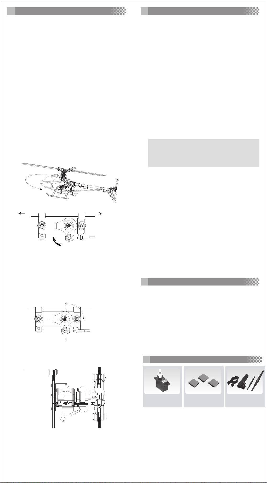
6.Fit the servo arm temporarily, check the gyro and servo
direction:
a.While giving the right rudder control, the servo arm
should move toward the nose of the helicopter.
b.While rotating the helicopter with your hand counter-
clockwise, the servo arm should move toward the
nose of the helicopter.
FLIGHT ADJUSTMENT
■
Gyro Gain
If the steps above are correctly executed, the gyro will be
in charge of the tail control under heading lock mode. Even
in crosswind situation, the tail will remain the position.
The gyro gain differs. The higher speed the rudder servo is,
the higher the gyro gain will be. On the contrary, the tail
efficiency of the helicopter itself increases when the head
speed of the helicopter goes up, so the gyro gain should be
reduced.
As a result, use gyro gain of 80~85% when hovering and
75~80% during aerobatics. Increase the gyro gain before
the tail begins to hunt. It will reduce the life of the servo if
the gain is too high.
■
Pirouette Adjustment
The pirouetting rate of the helicopter is related to the gyro
gain and the rudder ATV (or D/R) setting. Increase the ATV
(or D/R) will speed up the pirouetting rate. Under the same
ATV (or D/R value) setting, the higher the gyro gain is, the
slower the pirouetting rate will be. It is recommended to
decide the gyro gain first, and then adjust the pirouetting
to the rate you want. It is suggested to use the EXP
function of the rudder to make the control more precise.
WARNING
Make sure every part on the helicopter is installed very
well if you want the helicopter to pirouette at a very high
speed, or something will be flung out such as the gyro
itself due to the centrifugal force.
Nose
Tail
Rudder Servo
PS: Take mini Titan E325 for example. It may differ from
heli to heli.
7.Reset the power and remain the helicopter still, fit the
servo arm as shown. The servo arm should be perpendicular to the tail control linkage rod. If can’t be, it is
recommended to try another servo arm instead of
adjusting the “trim” or “sub trim”.
90˚
Rudder Servo
8.While the servo arm is perpendicular to the tail control
rod, the tail blades pitch should be at 0 degree or a little
offset to the right rudder as shown. (with clockwise
rotation rotor)
■
Vibration Elimination
TG-6000 uses the sensor with very high sensitivity. If there
is certain amount of vibration during flight, it will diminish
the performance of the gyro. So please take this issue very
seriously and take the following suggestion into consideration.
1.Use the provided foam only and make it very spongy to
be the damping.
2.Eliminate the source of vibration from the helicopter.
■
Trimming Elimination
1.It is recommended to reset the rudder trim when turning
on the gyro.
2.After taking off, you may use the rudder trim to diminish
the drift of tail.
3.Only use rudder trim during actual flying, not at setting
up process.
CAUTION
.
Always use the provided foam to install the gyro.
.
Mount the gyro so that there is no object will touch it.
.
Note the installation direction of the gyro itself.
.
Turn on the gyro under heading lock mode and never
move the helicopter until the red LED stops flashing.
.
Don’t use the “trim” and “sub trim” of rudder when
setting up.
.
Avoid sudden changes of temperature.
.
Disable the tail compensation (revolution mixing)
function when using the heading lock mode.
OPTIONAL PARTS
9.Move the rudder stick to the left and right, adjust and
check the linkage. Make sure there is no bending on
both sides.
10.Make sure the EPA dial should be above 70%, or the
servo arm is too long that the gyro gain can’t be
maximized.
8131
ACE RC Micro Rudder
Servo, C0915
AC2213
Spongy Foam
Manufactured by
THUNDER TIGER CORP.
http://www.thundertiger.com
AQ0847
Mini Plastic Screwdriver
JC2017
 Loading...